Difference between revisions of "DW-DISPATCH/ru"
Jump to navigation
Jump to search
(Created page with "<div class="caution"> ВНИМАНИЕ! Все работы, связанные с установкой, подключением, настройкой, обслуживан...") |
|||
| (7 intermediate revisions by the same user not shown) | |||
| Line 18: | Line 18: | ||
==МОДУЛЬ АВТОМАТИЧЕСКОГО СЧИТЫВАНИЯ ПОКАЗАНИЙ СЧЕТЧИКА== | ==МОДУЛЬ АВТОМАТИЧЕСКОГО СЧИТЫВАНИЯ ПОКАЗАНИЙ СЧЕТЧИКА== | ||
| − | Модуль предназначен только для системы диспетчеризации. Он не используется в основной системе Larnitech | + | Модуль предназначен только для системы диспетчеризации. Он не используется в основной системе для Умного дома Larnitech. |
<div class="caution"> | <div class="caution"> | ||
| Line 35: | Line 35: | ||
</div> | </div> | ||
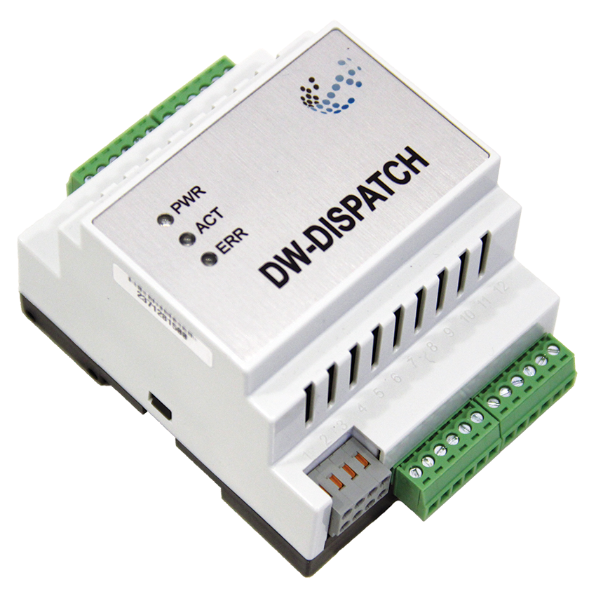
| − | == | + | ==Изображение модуля== |
[[File:DISPATCH VIEW.jpg|500px]] | [[File:DISPATCH VIEW.jpg|500px]] | ||
| − | == | + | ==Размеры модуля== |
[[File:DISPATCH DIM.png|500px]] | [[File:DISPATCH DIM.png|500px]] | ||
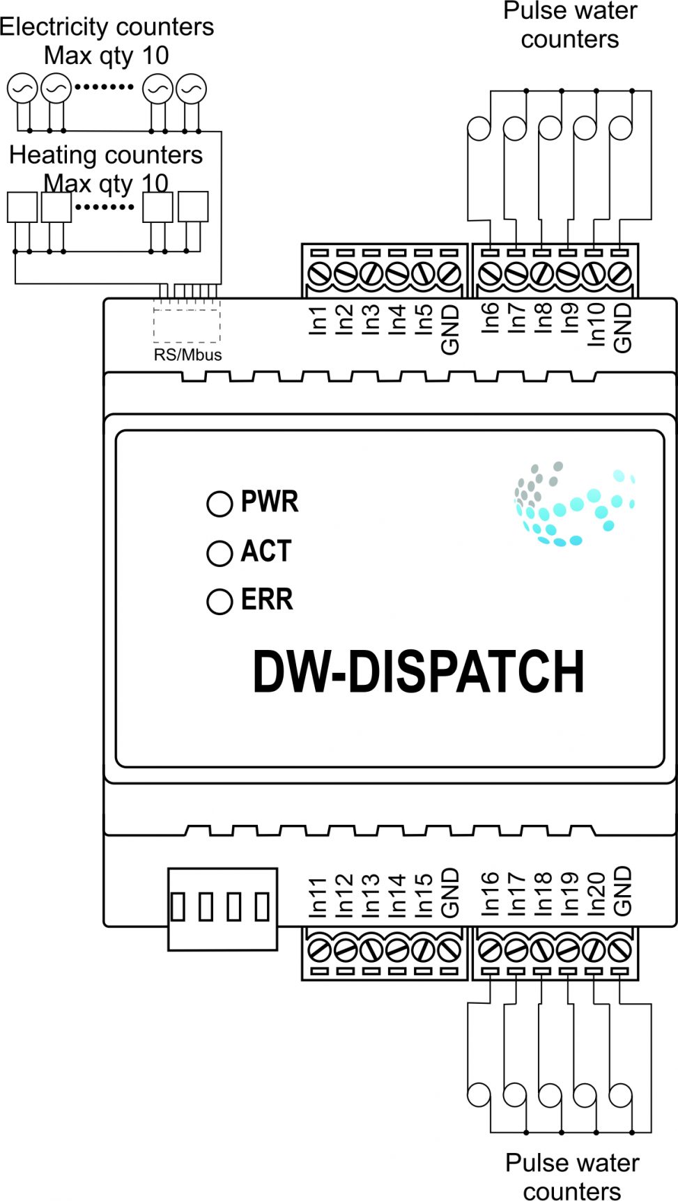
| − | == | + | ==Пример подключения== |
[[File:DISPATCH EXA.jpg|500px]] | [[File:DISPATCH EXA.jpg|500px]] | ||
| − | == | + | ==Параметры модуля== |
{{ Mp | {{ Mp | ||
| Line 65: | Line 65: | ||
}} | }} | ||
| − | == | + | ==Индикация работы модуля== |
{{indicationold}} | {{indicationold}} | ||
| − | == | + | ==Порядок установки и подключения модуля== |
| − | # | + | #Установите модуль в распределительный щит на DIN-рейку и закрепите специальной защелкой, расположенной на основании модуля. |
| − | # | + | #Подсоедините разъемы X1-X4. |
| − | # | + | #Подключите разъем CAN. |
| − | # | + | #Настройте модуль с помощью LT SETUP. |
| − | # | + | #Проверьте все оборудование на правильность работы. |
| − | == | + | ==Отключение модуля и процедура демонтажа== |
| − | # | + | #Отсоедините разъем CAN |
| − | # | + | #Отсоедините разъемы X1-X4. |
| − | # | + | #Снимите модуль с DIN-рейки, освободив защелку, расположенную в нижней части основания модуля. |
Latest revision as of 15:09, 29 January 2022
| DW-DISPATCH | |||||||
|---|---|---|---|---|---|---|---|
 | |||||||
| |||||||
| |||||||
МОДУЛЬ АВТОМАТИЧЕСКОГО СЧИТЫВАНИЯ ПОКАЗАНИЙ СЧЕТЧИКА
Модуль предназначен только для системы диспетчеризации. Он не используется в основной системе для Умного дома Larnitech.
ВНИМАНИЕ! Все работы, связанные с установкой, подключением, настройкой, обслуживанием и поддержкой оборудования, должны выполняться только квалифицированным персоналом, обладающим достаточными навыками и опытом работы с электрооборудованием! Во избежание риска возгорания, поражения электрическим током, повреждения системы и/или травм, установка и сборка системы должны выполняться в соответствии с указаниями, перечисленными ниже:
- все работы по подключению должны выполняться при выключенном питании;
- необходимо использовать соответствующие инструменты и средства индивидуальной защиты от поражения электрическим током;
- запрещается использовать поврежденные кабели, провода и разъемы;
- избегайте перегиба проводов и кабелей;
- не прилагайте чрезмерных усилий к проводам путем их перегиба или слишком сильного сжатия: внутренние проводники кабелей и проводов могут быть оголены или повреждены;
- не используйте для подключения разъемы с плохими контактами;
- не превышайте параметры предельной нагрузки, указанные в инструкции;
- сечение питающих проводов зависит от требований к пределу плотности тока, типу изоляции и материалу проводов. Недостаточное сечение провода может привести к перегреву кабеля и возгоранию.
Когда питание включено, НИКОГДА:
- не подключайте/отключайте разъемы;
- не открывайте модули и датчики.
Изображение модуля
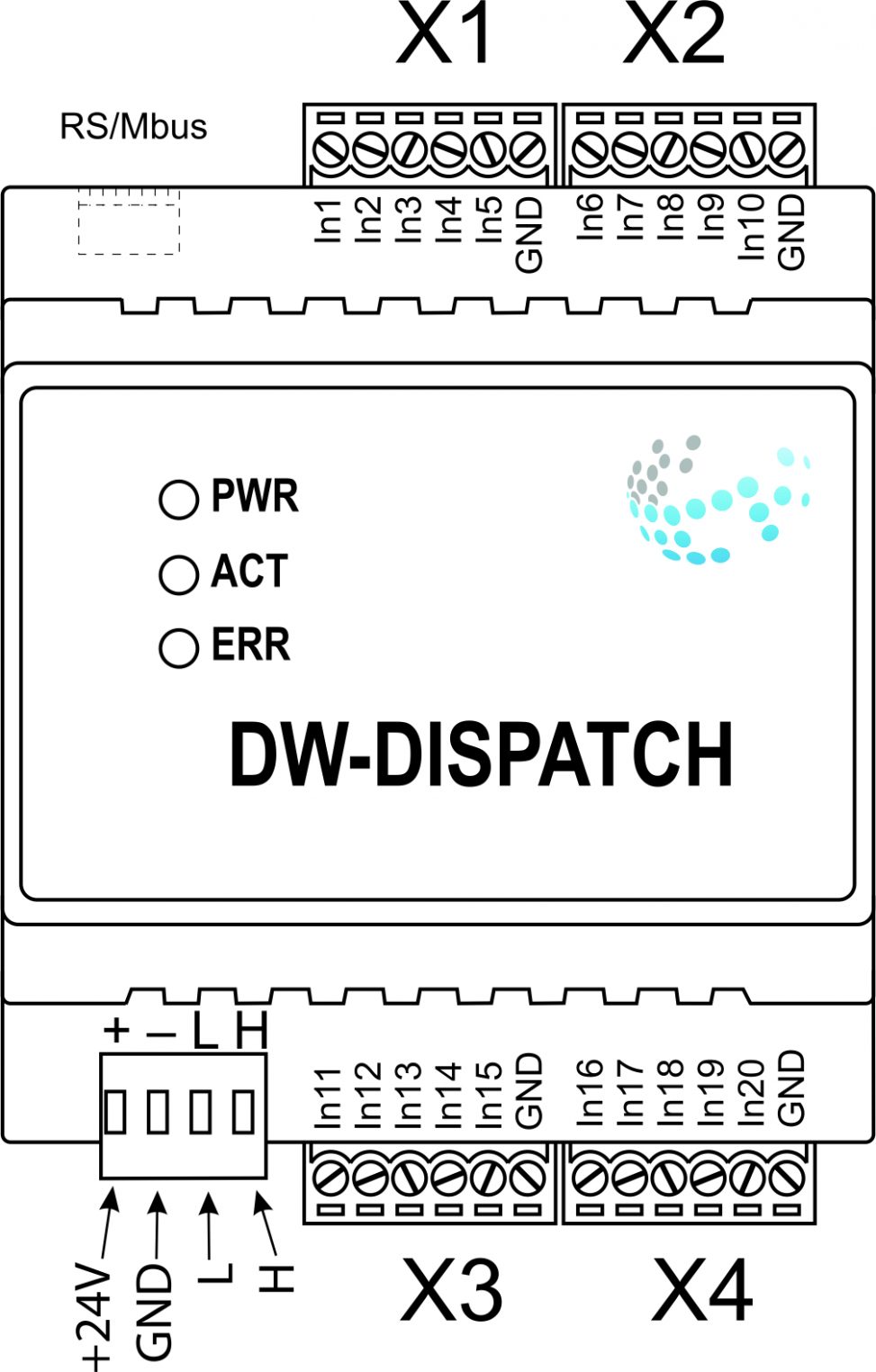
Размеры модуля
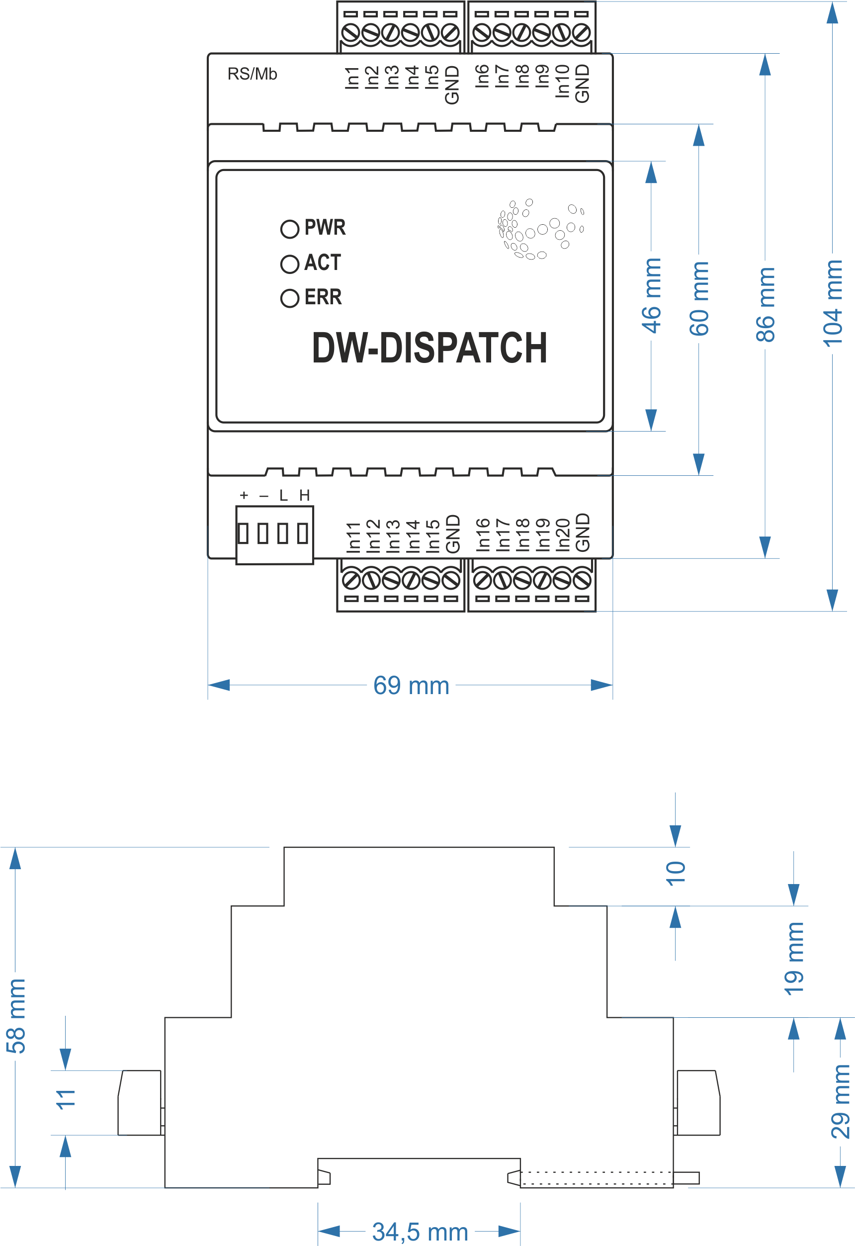
Пример подключения
Параметры модуля
| Parameter name | Value |
|---|---|
| RS485 ports qty | 1 |
| M-BUS port quantity | 1 |
| Pulse inputs quantity | 20 |
| Power supply | 11.5 … 27.5 V DC from CAN |
| Max current(24V) | 45 mA |
| Push-button/reed switches line recommended length | 300m |
| Bus type | CAN (4-wire) |
| Equipment installation type | DIN rail (EN 60715) |
| Case material | ABS |
| Protection | IP40 |
| Temperature range | -10 … +50 °C |
| Size | 4U, 69x104x58 mm |
| Weight | 130g |
Индикация работы модуля
| Indicator | Status | Description |
|---|---|---|
| Power | Power | |
| Power not available | ||
| Activity | Data communication | |
| Data communication not available | ||
| Error | No errors | |
| Overheating | ||
| The data has not been transferred via the CAN bus for at least 5 minutes. |
Порядок установки и подключения модуля
- Установите модуль в распределительный щит на DIN-рейку и закрепите специальной защелкой, расположенной на основании модуля.
- Подсоедините разъемы X1-X4.
- Подключите разъем CAN.
- Настройте модуль с помощью LT SETUP.
- Проверьте все оборудование на правильность работы.
Отключение модуля и процедура демонтажа
- Отсоедините разъем CAN
- Отсоедините разъемы X1-X4.
- Снимите модуль с DIN-рейки, освободив защелку, расположенную в нижней части основания модуля.