Difference between revisions of "Translations:Metaforsa 3/3.plus/29/sk"
From Larnitech wiki page
Jump to navigation
Jump to search
Tags : Mobile web edit Mobile edit
(No difference)
Latest revision as of 12:42, 8 April 2024
Information about message (contribute ) This message has no documentation.
If you know where or how this message is used, you can help other translators by adding documentation to this message.
Message definition (Metaforsa 3/3.plus )
{| class="wikitable"
{| class="wikitable"
|+ text-align="left"|'''Table 2'''
|-
!Connector!!Contact!!Assignment
|-
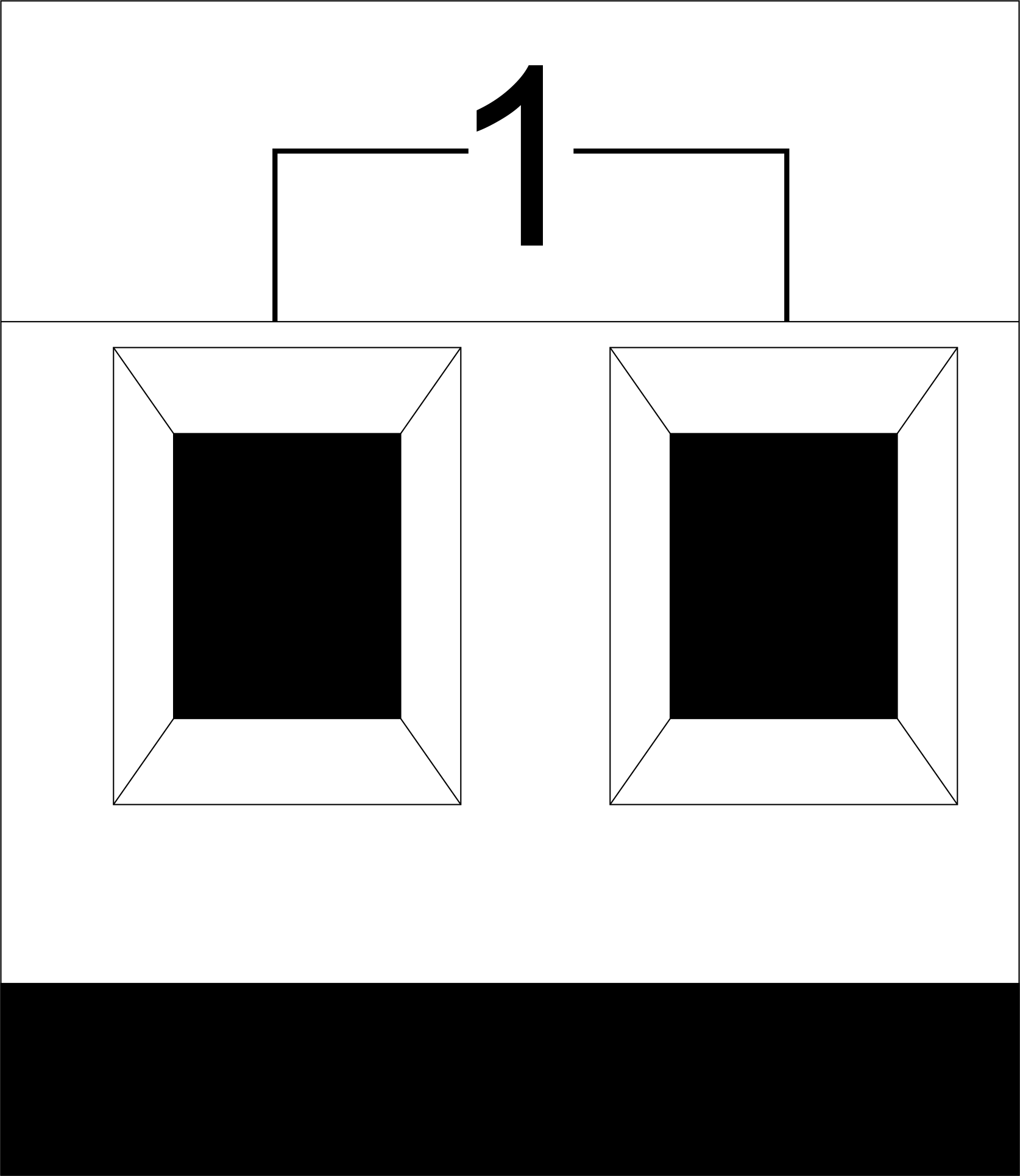
|[[File:Out.png|80px|frameless]] ||1-10|| Load application (light lamps, thermal actuators, etc.)
|-
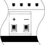
|[[File:Dimm.png|80px|frameless]] ||D1-4, L, N|| Load application (dimming lamps)
|-
| colspan="2"| Device status indicators || The module status indicators are described in '''table 3'''
|-
|[[File:24vconn.png|80px|frameless]] ||+24V<br>GND|| +24V — module power supply by an external 24 V power supply GND — common
|-
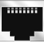
|[[File:Rj45.jpg|80px|frameless]] ||RJ45|| Connector for LAN connectivity
|-
|[[File:IOC_CONN.png|80px|frameless]] ||In1-14, In15-28 GND|| Controlling devices connection (buttons, LED buttons, magnetic reed switches, motion detectors, leakage sensors, temperature sensors, etc.): <br>In1 … In28 — logic inputs <br>GND — common
|-
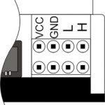
|[[File:Can.jpg|80px|frameless]] ||VCC<br>GND<br>L<br>H|| External modules connection for CAN-bus<br>VСС — 24V output for external devices power supply<br>GND — common<br>L — CAN-L data bus<br>H — CAN-H data bus
|} Translation {| class="wikitable"
Tabulka 2
Konektor
Kontakt
Zadanie
1-10
Aplikácia záťaže (svetelné lampy, tepelné pohony atď.)
D1-4, L, N
Aplikácia záťaže (stmievanie žiaroviek)
Indikátory stavu zariadenia
Indikátory stavu modulu sú popísané v tabuľke 3
+24V
+24V — napájanie modulu externým 24V zdrojom GND — spoločné
RJ45
Konektor pre LAN pripojenie
In1-14, In15-28 GND
Pripojenie ovládacích zariadení (tlačidlá, LED tlačidlá, magnetické jazýčkové spínače, detektory pohybu, snímače úniku, snímače teploty atď.):
VCC
Pripojenie externých modulov pre zbernicu CAN