Tags : Mobile web edit Mobile edit
(No difference)
Latest revision as of 14:57, 2 January 2022
Information about message (contribute ) This message has no documentation.
If you know where or how this message is used, you can help other translators by adding documentation to this message.
Message definition (Metaforsa MF-10 )
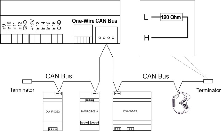
Expansion modules include Larnitech equipment connected through the CAN-bus. Such equipment includes: dimmers, RGB-backlit control modules, multimode sensors, etc. The equipment connected to the expansion port is defined automatically and does not require any preset tuning. Connector contact pin assignment is defined in '''Table 4'''. The example of connection is shown in '''fig. 21.'''
Expansion modules include Larnitech equipment connected through the CAN-bus. Such equipment includes: dimmers, RGB-backlit control modules, multimode sensors, etc. The equipment connected to the expansion port is defined automatically and does not require any preset tuning. Connector contact pin assignment is defined in '''Table 4'''. The example of connection is shown in '''fig. 21.'''
{|class="wikitable" style="width:700px"
|-
|[[File:mf10exa21.jpg|700px]]<br>'''Fig. 21'''
|- style="background-color:#dededf"
|'''Caution! The 120 ohm terminating resistors should be installed at the end connectors between L and H contact points of CAN-bus. Ensure the connection is correct. The incorrect connection may cause sensor and/or module malfunction.'''
|}
===Module installation and connection procedure===
Translation Expansion modules include Larnitech equipment connected through the CAN-bus. Such equipment includes: dimmers, RGB-backlit control modules, multimode sensors, etc. The equipment connected to the expansion port is defined automatically and does not require any preset tuning. Connector contact pin assignment is defined in '''Table 4'''. The example of connection is shown in '''fig. 21.''' Expansion modules include Larnitech equipment connected through the CAN-bus. Such equipment includes: dimmers, RGB-backlit control modules, multimode sensors, etc. The equipment connected to the expansion port is defined automatically and does not require any preset tuning. Connector contact pin assignment is defined in Table 4 . The example of connection is shown in fig. 21.
Fig. 21
Caution! The 120 ohm terminating resistors should be installed at the end connectors between L and H contact points of CAN-bus. Ensure the connection is correct. The incorrect connection may cause sensor and/or module malfunction.
Module installation and connection procedure