Difference between revisions of "Translations:DW-DALI.A/13/ru"
Jump to navigation
Jump to search
(Created page with "The physical configuration and contact point assignment of each connector are shown in table {| class="wikitable" |+ text-align="left"|'''Table2''' |- !Connector!!Contact!! st...") |
(No difference)
|
Revision as of 14:13, 7 January 2022
The physical configuration and contact point assignment of each connector are shown in table
| Connector | Contact | Assignment |
|---|---|---|
1 DALI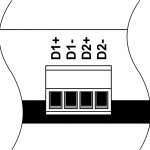 |
D1+ D1- D2+ D2- |
DALI1 bus DALI2 bus |
| 2 DALI power supply |
+24V GND |
+24V — DALI bus power supply GND — common |
| 3 Module indicating unit |
The scenario for module indicating unit is shown below | |
| 4 CAN |
VCC GND L H |
VСС — +24V power supply of CAN-bus GND — common L — CAN-L data bus H — CAN-H data bus |