Difference between revisions of "BW-SW24V"
Jump to navigation
Jump to search
(Marked this version for translation) |
|||
| Line 1: | Line 1: | ||
<languages/> | <languages/> | ||
<translate> | <translate> | ||
| + | <!--T:1--> | ||
{{RevisionChanger | hasA/B = 1 | hasC = 1}} | {{RevisionChanger | hasA/B = 1 | hasC = 1}} | ||
{{Infobox module | {{Infobox module | ||
| Line 13: | Line 14: | ||
}} | }} | ||
| − | ==24V BUTTONS INPUT MODULE== | + | ==24V BUTTONS INPUT MODULE== <!--T:2--> |
| + | <!--T:3--> | ||
This module is used to connect 24V buttons w/wo LED backlighting. | This module is used to connect 24V buttons w/wo LED backlighting. | ||
| − | ==Example of connection== | + | ==Example of connection== <!--T:4--> |
| + | <!--T:5--> | ||
[[File:SW24VC EXA1.png|500px]] | [[File:SW24VC EXA1.png|500px]] | ||
<br> | <br> | ||
| Line 37: | Line 40: | ||
common='C' – use Out0 as common catode | common='C' – use Out0 as common catode | ||
| − | ==Module parameters== | + | ==Module parameters== <!--T:6--> |
| + | <!--T:7--> | ||
{{ Mp | {{ Mp | ||
| outqty = 6 | | outqty = 6 | ||
| Line 56: | Line 60: | ||
}} | }} | ||
| − | ==Module installation and connection procedure== | + | ==Module installation and connection procedure== <!--T:8--> |
| + | <!--T:9--> | ||
#Connect the inputs and outputs. | #Connect the inputs and outputs. | ||
#Connect the CAN connector. | #Connect the CAN connector. | ||
| Line 63: | Line 68: | ||
#Check all equipment for proper operation. | #Check all equipment for proper operation. | ||
| − | ==Module shut-off and deinstallation procedure== | + | ==Module shut-off and deinstallation procedure== <!--T:10--> |
| + | <!--T:11--> | ||
#Disconnect the CAN connector. | #Disconnect the CAN connector. | ||
#Disconnect the inputs and outputs.. | #Disconnect the inputs and outputs.. | ||
| − | ==HW settings== | + | ==HW settings== <!--T:12--> |
{|class="wikitable" | {|class="wikitable" | ||
|- | |- | ||
Latest revision as of 12:54, 9 January 2022
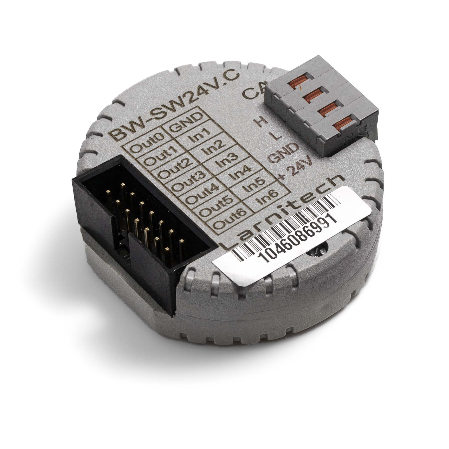
| BW-SW24V.C | |||||||||
|---|---|---|---|---|---|---|---|---|---|
 | |||||||||
| |||||||||
| |||||||||
24V BUTTONS INPUT MODULE
This module is used to connect 24V buttons w/wo LED backlighting.
Example of connection
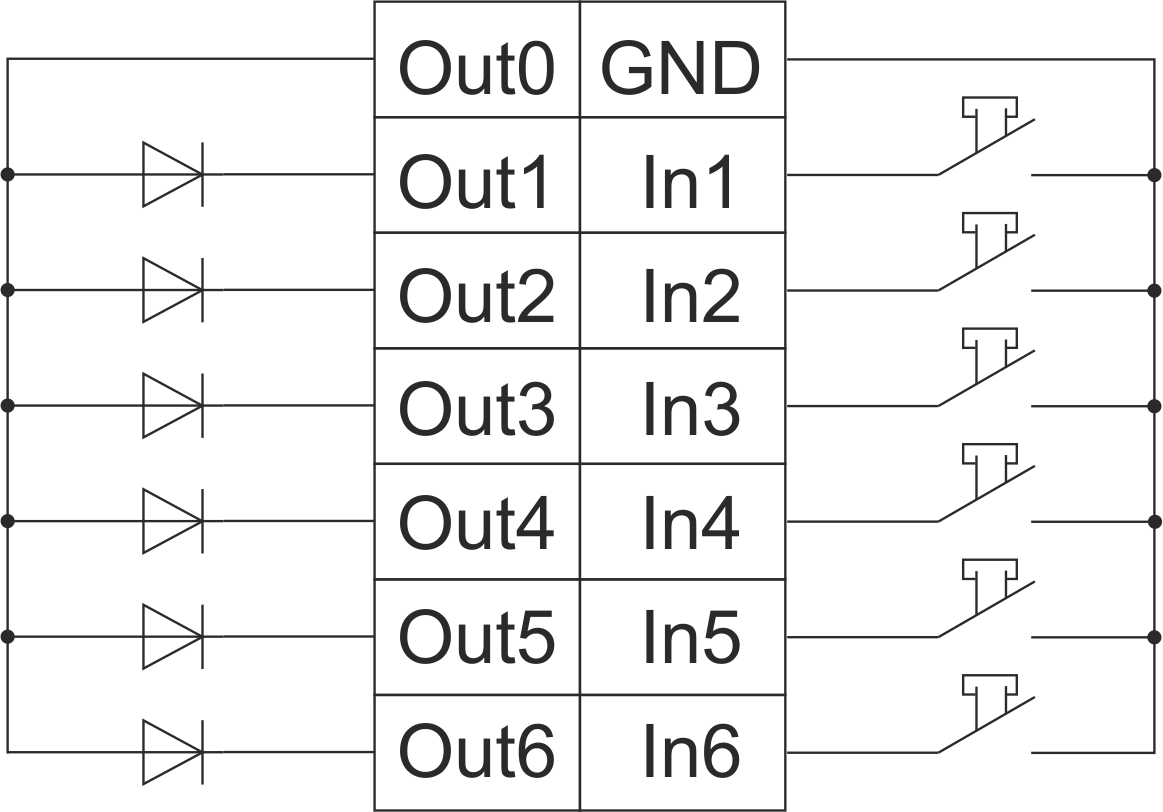
HW example:
1hw="in='BBBBBB' out='BBBBBB' common='A'"
6 common-wire buttons with common-anode 24 V DC LEDs
common='A' – use Out0 as common anode
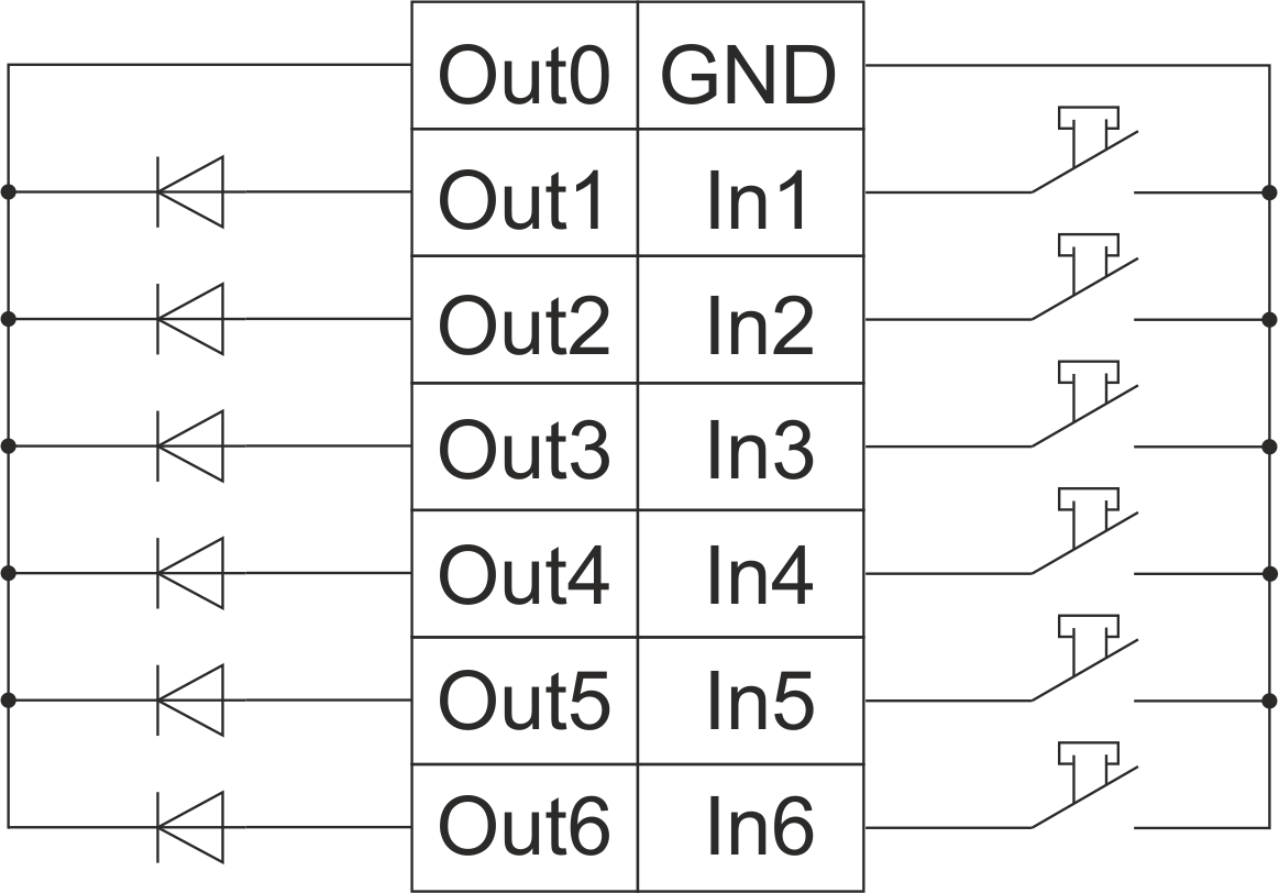
HW example:
1hw="in='BBBBBB' out='BBBBBB' common='C'"
6 common-wire buttons with common-catode 24 V DC LEDs common='C' – use Out0 as common catode
Module parameters
| Parameter name | Value |
|---|---|
| Input channels qty | 6 |
| Buttons | 6 |
| LED Buttons | 6 |
| Output channels qty | 6 |
| Backlight voltage | 11.5 … 27.5 V DC (from CAN) |
| Power supply | 11.5 … 27.5 V DC from CAN |
| Max current(24V) | 30 mA |
| Bus type | CAN (4-wire) |
| Equipment installation type | Free |
| Case material | ABS |
| Protection | IP40 |
| Temperature range | -10 … +50 °C |
| Size | 45x42x14 mm |
| Weight | 25 g |
Module installation and connection procedure
- Connect the inputs and outputs.
- Connect the CAN connector.
- Configure the module using LT setup.
- Check all equipment for proper operation.
Module shut-off and deinstallation procedure
- Disconnect the CAN connector.
- Disconnect the inputs and outputs..
HW settings
| Name | Type, range | SUBID | Default | Description |
|---|---|---|---|---|
| in | char[6] | 98 | 'BBBBBB' | Each char is responsible for the type of a particular channel
Example: in='BB-C-C' |
| out | char[6] | 98 | 'BBBBBB' | Each char is responsible for the type of a particular channel
Example: out='BBLILI' |
| common | char | 98 | 'C' | LED common wire
Example: common='C' |