Difference between revisions of "BW-010"
Jump to navigation
Jump to search
(Marked this version for translation) |
|||
| (3 intermediate revisions by 2 users not shown) | |||
| Line 1: | Line 1: | ||
| + | <languages/> | ||
| + | <translate> | ||
| + | <!--T:1--> | ||
{{RevisionChanger | hasA = 1 | hasC = 1}} | {{RevisionChanger | hasA = 1 | hasC = 1}} | ||
| + | {{Infobox module | ||
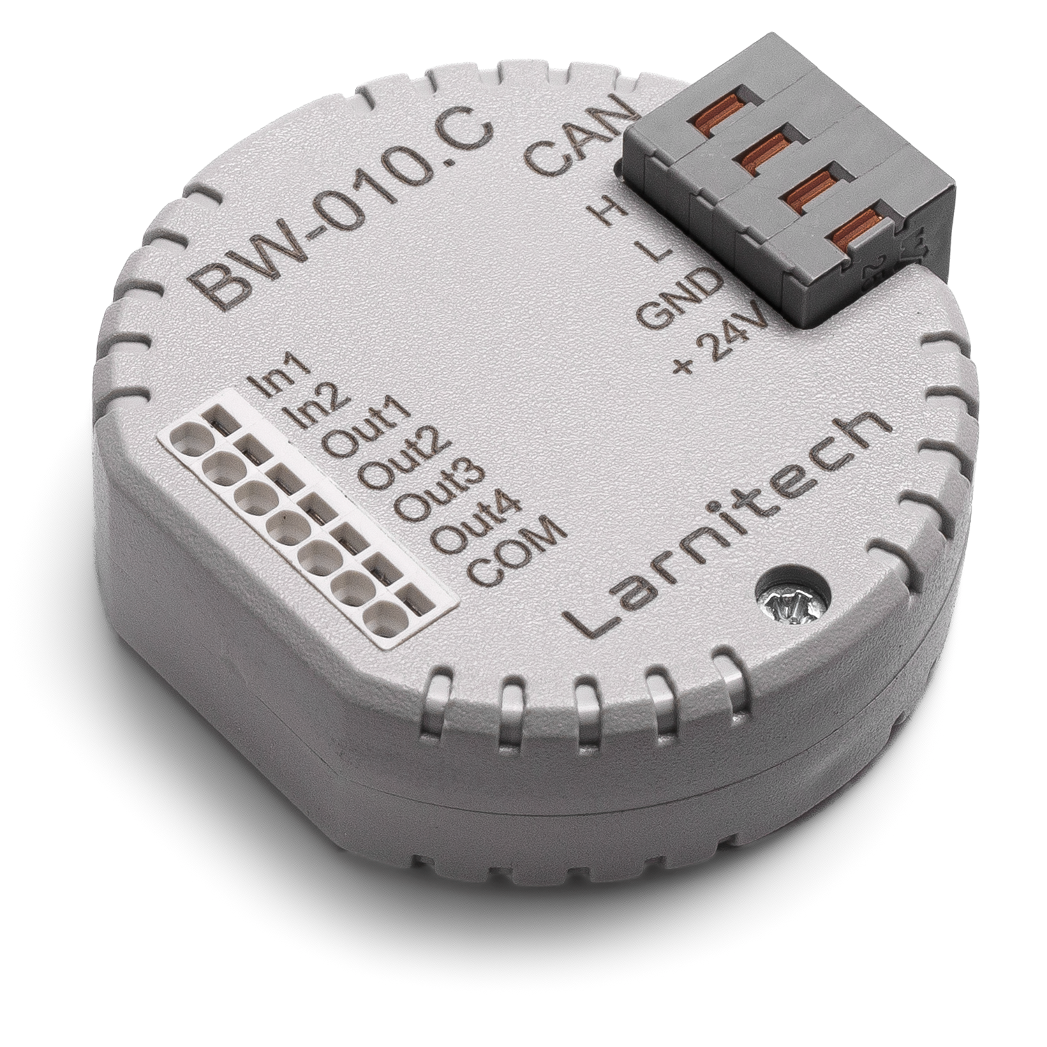
| + | | name = BW-010.C | ||
| + | | image = BW-010C.png | ||
| + | | 010out = 4 | ||
| + | | 010in = 2 | ||
| + | | peakl = 15mA | ||
| + | | voltage = 11.5...27.5 V DC | ||
| + | | dim = 45x42x14 mm | ||
| + | }} | ||
| + | ==4-CHANNEL MODULE FOR DEVISES WITH 0-10V INPUT OR 0-10V OUTPUT== <!--T:2--> | ||
| − | + | <!--T:3--> | |
| − | |||
This module allows connecting devices with 0-10V input or output interfaces | This module allows connecting devices with 0-10V input or output interfaces | ||
to the Smart Home system. | to the Smart Home system. | ||
| + | <!--T:4--> | ||
<div class="caution"> | <div class="caution"> | ||
CAUTION! All work related to the installation, connection, setting up, service and support must be carried out by qualified personnel with sufficient skills and experience in working with electrical equipment. | CAUTION! All work related to the installation, connection, setting up, service and support must be carried out by qualified personnel with sufficient skills and experience in working with electrical equipment. | ||
| Line 23: | Line 36: | ||
</div> | </div> | ||
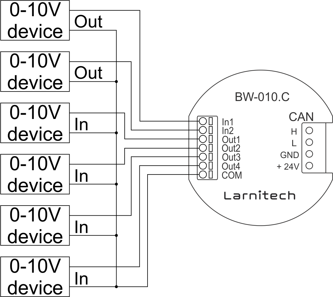
| − | ==Example of connection== | + | ==Example of connection== <!--T:5--> |
| + | <!--T:6--> | ||
[[File:BW010C EXA.png|500px]] | [[File:BW010C EXA.png|500px]] | ||
| − | ==Module parameters== | + | ==Module parameters== <!--T:7--> |
| + | <!--T:8--> | ||
{{ Mp | {{ Mp | ||
| 010inqty = 2 | | 010inqty = 2 | ||
| Line 44: | Line 59: | ||
}} | }} | ||
| − | ==Module installation and connection procedure== | + | ==Module installation and connection procedure== <!--T:9--> |
| + | <!--T:10--> | ||
#Connect the interface connector. | #Connect the interface connector. | ||
#Connect the CAN connector. | #Connect the CAN connector. | ||
| Line 51: | Line 67: | ||
#Check all equipment for proper operation. | #Check all equipment for proper operation. | ||
| − | ==Module shut-off and deinstallation procedure== | + | ==Module shut-off and deinstallation procedure== <!--T:11--> |
| + | <!--T:12--> | ||
#Disconnect the CAN connector. | #Disconnect the CAN connector. | ||
#Disconnect the interface connector. | #Disconnect the interface connector. | ||
| − | ==HW settings== | + | ==HW settings== <!--T:13--> |
{|class="wikitable" | {|class="wikitable" | ||
|- | |- | ||
| Line 84: | Line 101: | ||
|} | |} | ||
| + | <!--T:14--> | ||
<syntaxhighlight lang="xml" line> | <syntaxhighlight lang="xml" line> | ||
<item addr="377:1" auto-period="600" cfgid="170" name="Dimmer 1" type="dimmer-lamp"/> | <item addr="377:1" auto-period="600" cfgid="170" name="Dimmer 1" type="dimmer-lamp"/> | ||
| Line 94: | Line 112: | ||
<item addr="377:98" cfgid="170" logic-ver="19" name="Temperature" system="yes" type="temperature-sensor"/> | <item addr="377:98" cfgid="170" logic-ver="19" name="Temperature" system="yes" type="temperature-sensor"/> | ||
</syntaxhighlight> | </syntaxhighlight> | ||
| + | </translate> | ||
Latest revision as of 14:10, 9 January 2022
| BW-010.C | |||||||
|---|---|---|---|---|---|---|---|
 | |||||||
| |||||||
| |||||||
4-CHANNEL MODULE FOR DEVISES WITH 0-10V INPUT OR 0-10V OUTPUT
This module allows connecting devices with 0-10V input or output interfaces to the Smart Home system.
CAUTION! All work related to the installation, connection, setting up, service and support must be carried out by qualified personnel with sufficient skills and experience in working with electrical equipment. To avoid the risk of fire, electric shock, damage to the system and/or personal injury, the system installation and assembly must be performed in accordance with the instructions listed below:
- all connectivity work must be carried out with the power turned OFF;
- use appropriate tools and personal protection against electric shock;
- do not use damaged cables, wires and connectors;
- avoid folding the cables and wires;
- do not apply excessive force to the wires by kinking or pressing them too hard: the inner conductors of the cables and wires may get stripped or damaged;
- do not use the power socket with poor contacts to connect;
- do not exceed the load limit parameters specified in the manual;
- the supply conductors wire section is subject to the specifications for current density limit, insulation type and wire material. Light section can result in cable overheating and fire.
When the power is on, NEVER:
- connect/disconnect the connectors;
- open modules and sensors.
Example of connection
Module parameters
| Parameter name | Value |
|---|---|
| 0-10 input port quantity | 2 |
| 0-10 output port quantity | 4 |
| Max load per channel | 15mA |
| Power supply | 11.5 … 27.5 V DC from CAN |
| Max current(24V) | 55 mA |
| Bus type | CAN (4-wire) |
| Equipment installation type | Free |
| Case material | ABS |
| Protection | IP40 |
| Temperature range | -10 … +50 °C |
| Size | 45x42x14 mm |
| Weight | 15 g |
Module installation and connection procedure
- Connect the interface connector.
- Connect the CAN connector.
- Configure the module using LT setup.
- Check all equipment for proper operation.
Module shut-off and deinstallation procedure
- Disconnect the CAN connector.
- Disconnect the interface connector.
HW settings
| Name | Type, range | SUBID | Default | Description |
|---|---|---|---|---|
| def | integer 0-250 | 1-4 | 100 | The default brightness level in case of a power reset (1..250). Example: def=250 |
| min | integer 0-100 | 1-4 | 0 | Minimum dimming level, example: min=10 |
| max | integer 0-100 | 1-4 | 100 | Maximum dimming level, example max=95 |
| start | integer 0-100 | 1-4 | 0 | The Start function is used for lamps that lack the minimal voltage to get turned on. If the set value is lower than the start value, the lamp is turned on at the start value and them the light is dimmed down to the set level. Example: start=60 |
| force | integer 0-100 | 1-4 | 10 | Time duration of the starting value (measured in milliseconds). Example: force=20 |
| runtime | integer 0-60000 | 1-4 | 1000 | Runtime is the speed of changing the brightness from 'min' to 'max' (measured in milliseconds). Example: runtime=1000 |
| dm | char[4] | 98 | 'vvvv' | Each char is responsible for the type of a particular channel
Example: dm='skl-' |
1<item addr="377:1" auto-period="600" cfgid="170" name="Dimmer 1" type="dimmer-lamp"/>
2<item addr="377:2" auto-period="600" cfgid="170" name="Dimmer 2" type="dimmer-lamp"/>
3<item addr="377:3" auto-period="600" cfgid="170" name="Dimmer 3" type="dimmer-lamp"/>
4<item addr="377:4" auto-period="600" cfgid="170" name="Dimmer 4" type="dimmer-lamp"/>
5<item addr="377:31" cfgid="170" name="Voltage" system="yes" type="voltage-sensor"/>
6<item addr="377:32" cfgid="170" name="Voltage" system="yes" type="voltage-sensor"/>
7<item addr="377:97" cfgid="170" name="Temperature" system="yes" type="temperature-sensor"/>
8<item addr="377:98" cfgid="170" logic-ver="19" name="Temperature" system="yes" type="temperature-sensor"/>