Difference between revisions of "Metaforsa2 MF-14/ru"
(Created page with "*разъем (1) - подключение устройств; *разъем (2) - подключение диммирующего освещения;") |
(Created page with "В нижней части корпуса ('''рис. 1''') расположены:") |
||
| Line 270: | Line 270: | ||
| − | + | В нижней части корпуса ('''рис. 1''') расположены: | |
Revision as of 11:53, 4 January 2022
| MF-14 | |||||||||||||
|---|---|---|---|---|---|---|---|---|---|---|---|---|---|
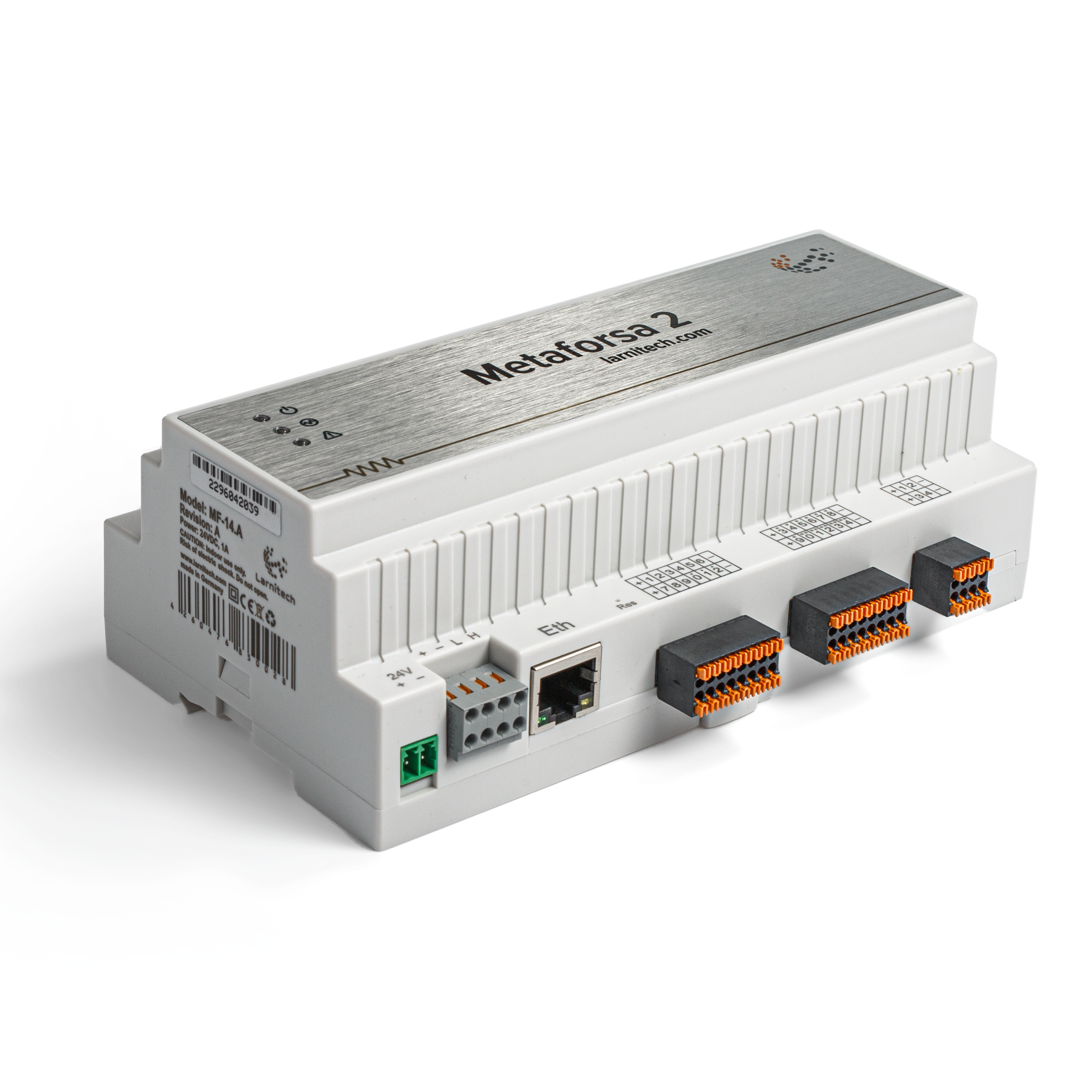 | |||||||||||||
| |||||||||||||
| |||||||||||||
| |||||||||||||
Введение
Руководство по установке модуля METAFORSA SMART HOUSE описывает порядок его установки, сборки, эксплуатации и настройки. При работе с системой необходимо строго соблюдать все требования, изложенные в данном руководстве. Несоблюдение этих требований может привести к повреждению устройства, его выходу из строя, поражению электрическим током, возгоранию и другим последствиям. Производитель оставляет за собой право вносить изменения в данное руководство без предварительного уведомления. Это руководство является неотъемлемой частью системы и должно храниться у конечного потребителя.
Функции
- 10 универсальных выходов обеспечивают управление:
- Освещением
- Клапанами отопления NC/NO
- Жалюзи
- 1- или 2-х полюсными воротами
- 1- или 2-х полюсными клапанами
- Замками NC/NO
- Фанкойлами
- 4-мя выходами диммирования
- 8-ю выходами PWM
- 24 отдельных входа обеспечивают управление:
- Кнопками
- Выключателями
- герконами
- датчиками утечек
- детекторами движения
- 4 цифровых входа для 8 датчиков температуры
- Порт расширения
- Реле с контактами AgSnO2, рассчитаны на пиковую нагрузку 80 А, 20 мсек.
- Облачное подключение и управление всеми системами дома
- Голосовое управление (Siri, Alexa, Google Home)
- Движок плагинов позволяет расширить возможности системы (например, интеграция светильников Satel, Philips Hue, IKEA)
- Защита от несанкционированного доступа обеспечивается за счет шифрования RSA/AES256
- Push-уведомления от системы на вашем смартфоне (также можно получать через мессенджеры Telegram и Viber)
- История (сохраняются данные счетчика за 1 год)
- Plug and play (возможность быстрого и удобного расширения системы)
- Регулярные обновления системы
- Большая постоянно обновляемая база скриптов для удовлетворения всех ваших потребностей
- Автоматическое ежедневное резервное копирование через облако с возможностью восстановления первоначальной конфигурации
- Открытый API (который позволяет интегрировать Larnitech в другие системы)
- Интерактивный и удобный веб-интерфейс LT SETUP, доступный для расширенной настройки
- Plug and play
- Полностью готовый к установке комплект системы для Умного дома.
Требования безопасности
Во избежание риска возгорания, поражения электрическим током, повреждения системы и/или травм, установка и сборка системы должны выполняться в соответствии с инструкциями, перечисленными ниже:
- все работы по подключению должны производиться на обесточенном оборудовании;
- необходимо использовать соответствующие инструменты и средства индивидуальной защиты от поражения электрическим током;
- запрещается использовать поврежденные кабели, провода и разъемы;
- избегайте перегиба проводов и кабелей;
- не пережимайте и не перегибайте кабели и провода, прилагая чрезмерные усилия. В противном случае внутренние проводники кабеля и проводов могут быть оголены или повреждены;
- не используйте для подключения разъемы с плохими контактами;
- не превышайте предельные параметры нагрузки, указанные в данном руководстве;
- сечение питающих проводов зависит от требований к пределу плотности тока, типу изоляции и материалу проводов. Недостаточное сечение может привести к перегреву кабеля и возгоранию.
При работе с системой после подачи напряжения НИКОГДА:
- не производите подключение/отключение разъемов;
- не открывайте модули и датчики.
Конфигурация и назначение системы
Назначение системы
METAFORSA SMART HOUSE - это готовое решение для автоматизации жилых и коммерческих помещений, гостиничных комплексов, которое включает в себя самые востребованные функции Умного дома.
Устройство имеет 10 каналов управления, 4 канала диммирования, 24 входных канала для датчиков и порт для подключения цифровых датчиков.
| Универсальные выходы могут использоваться для управления: | Универсальные входы позволяют подключать: |
|---|---|
| Освещение | Кнопки/коммутационные блоки |
| Коннекторы розеток | Магнитные герконы |
| Пол с подогревом | Магнитные герконы |
| Приводы для штор/ворот | Датчики протечки |
| Клапаны водоснабжения/отопления |
Порт подключения цифровых датчиков
Порт подключения цифровых датчиков позволяет подключать различные цифровые датчики, такие как датчики температуры, окружающего освещения, влажности и другие.
Порт расширения
Порт расширения позволяет модернизировать систему, подключая дополнительное оборудование, такое как модуль управления светодиодным освещением, диммированием, измерительными приборами и другими элементами. Комплект, полностью готовый к установке, включает в себя базовое оборудование и программное обеспечение.
Комплектация
В стандартную комплектацию входят:
| Основной модуль METAFORSA MF-14.А | 1 шт |
| Блок питания MEANWELL DR-15-12 | 1 шт |
| Датчик движения CW-MSD | 3 шт |
| Датчик протечки FW-WL.A | 2 шт |
| Термочувствительный элемент FW-TS.A | 4 шт |
| Магнитный геркон (датчик положения окон/дверей) | 4 шт |
| Фильтр подавления помех для Ethernet-кабеля | 1 шт |
| Шнур питания | 1 шт |
| Руководство по эксплуатации | 1 шт |
Основные технические характеристики системы
Основные технические характеристики модуля МЕТАФОРСА MF-14.A приведены в таблице 1/
| Название параметра | Значение |
|---|---|
| Выходные порты | |
| Количество релейных каналов | 10 |
| Количество релейных групп | 10 |
| Количество каналов диммирования | 4 |
| Напряжение коммутации | 0-250 В переменного/постоянного тока |
| Пиковая нагрузка (на один канал) | 16 А |
| Пиковая нагрузка (на устройство) | 160 А |
| Максимальная нагрузка на канал диммирования | 0,5 А (110 Вт при 220 В) |
| Тип диммера | МОП-транзистор |
| Тип диммирования | задний фронт импульса |
| Тип подключения кабеля питания | коннектор |
| Допустимое сечение кабеля питания для подключения в разъем: одножильный кабель многожильный кабель многожильный кабель с наконечником|| | |
| Входные порты | |
| Количество отдельных входов | 24 |
| Количество цифровых входов | 4 |
| Максимальный ток на разъемах постоянного напряжения | 50 мА |
| Другие параметры | |
| Рабочая температура окружающей среды | 0 … +45°С |
| Температура хранения/транспортировки | -20 … +60°С |
| Допустимая влажность | 0 … 95% (без конденсации) |
| Напряжение питания | 11,5… 27,5 В постоянного тока |
| Максимальная нагрузка | 1 А |
| Доступные интерфейсы | Ethernet, CAN, OneWire |
| Тип шины | CAN (4-х проводная) |
| CAN (4-х проводная) | 800 м* (витая пара 5 кат) |
| Тип провода шины CAN | FTP Cat 5E |
| Тип подключения шины CAN | коннектор |
| Максимальная длина цифровой линии | 30 м |
| Тип провода цифровой линии | UTP/FTP Cat 5E |
| Тип подключения цифровой линии | Коннектор RJ-12 |
| Максимальная длина LAN | 100 м |
| Тип провода цифровой линии | UTP/FTP Cat 5E |
| Максимальная длина LAN | 100 м |
| Тип провода LAN | UTP/FTP Cat 5E |
| Тип подключения LAN | Коннектор RJ-45 |
| Габаритные характеристики | 9U, 156x110x58 mm |
| Материал корпуса | АБС-пластик |
| Класс защиты | IP40 |
| Тип установки оборудования | DIN-рейка (EN 60715) |
| Масса | 400 г |
* - на протяженных линиях требуется установка дополнительных блоков питания; максимальная длина линии может быть уменьшена из-за различных факторов помех
Общая структура системы
Общий вид модуля представлен на рис. 1
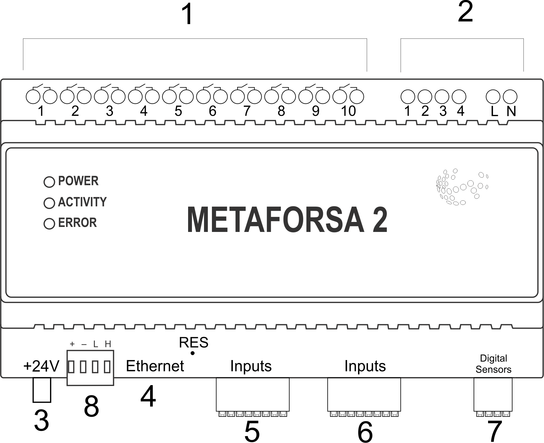
| 1 | — разъем для подключения нагрузки и питания |
| 2 | — разъем для подключения диммирующего освещения |
| 3 | — разъем питания |
| 4 | — разъем для подключения сети Ethernet |
| 5-6 | — разъемы для цифровых датчиков и кнопок/коммутационных устройств |
| 7 | — разъем интерфейса OneWire (для цифровых датчиков) |
| 8 | — разъем для модуля расширения. |
Общая схема внешних разъемов устройства METAFORSA
В верхней части корпуса (рис. 1) расположены:
- разъем (1) - подключение устройств;
- разъем (2) - подключение диммирующего освещения;
В нижней части корпуса (рис. 1) расположены:
- connector (3) — module power supply connection;
- connector (4) — Ethernet network connection;
- connectors (5-6) — four six-point connectors for digital sensors connection – motion, leakage, reed switch sensors, and *button/switching unit sensors;
- connector (7) — OneWire digital sensors bus connection;
- connector (8) — expansion module connection.
The physical configuration and contact point assignment of each connector are shown in table 2.
| Connector | Contact | Assignment |
|---|---|---|
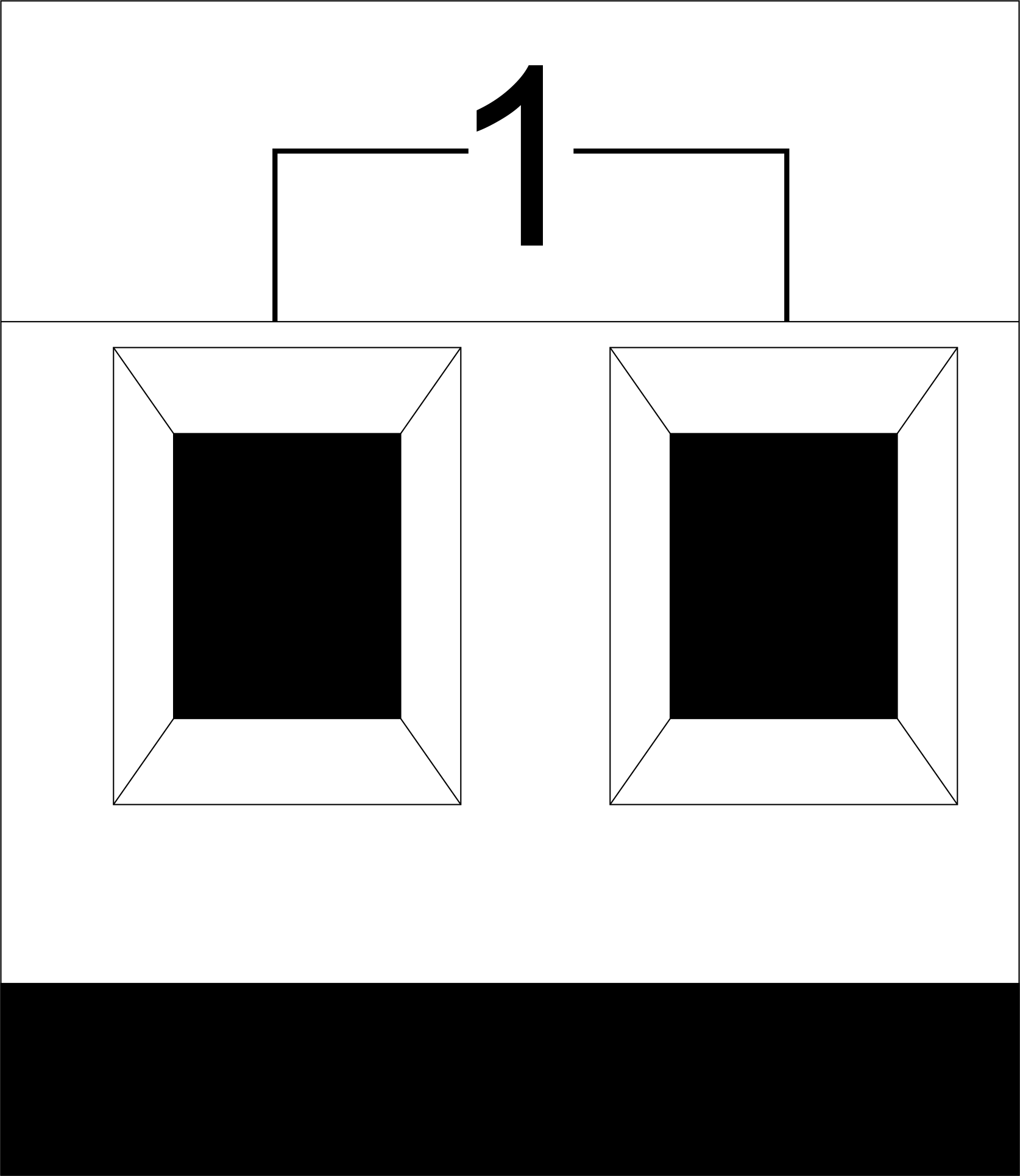 |
1-10 | Load application (light lamps, thermal actuators, etc.) |
| D1-4, L, N | Load application (dimming lamps) | |
| Device status indicators | The module status indicators are described in table 3 | |
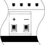 |
+24V GND |
+24V — module power supply by an external 24 V power supply GND — common |
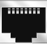 |
RJ45 | Connector for LAN connectivity |
| In1-12, In13-24 GND | Controlling devices connection (buttons, magnetic reed switches, motion or leakage sensors): +12V — sensor power output +12 V In1 … In24 — logic inputs (0-12 V) GND — common | |
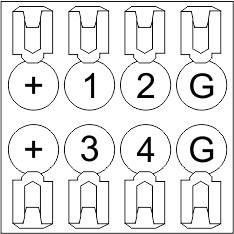 |
OneWire | Digital sensors connection (temperature) VCC — sensors power supply output +5V OW1-OW4 — OneWire data buses GND — common |
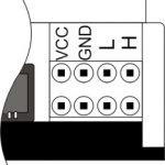 |
VCC GND L H |
External modules connection for CAN-bus VСС — 12V output for external devices power supply GND — common L — CAN-L data bus H — CAN-H data bus |
| Indicator | Status | Description |
|---|---|---|
| Power | Power | |
| Power not available | ||
| Activity | Data communication | |
| Data communication not available | ||
| Error | No errors | |
| Communication error | ||
| Module overheat | ||
| Dimmer outputs module overload | ||
| Absence of power on dimmers, if in configuration |
System installation and assembly
Before connecting the system, you must:
- site the sensor and actuators (if not pre-installed), set the sensors and actuators;
- site the module and power supply.
Note: The module must be installed near the power supply voltage source.
- The power of circuit breaker assembly must comply with the load capacity;
- Nothing else than the phase conductors can be connected to the module, the neutral wire is connected separately.
Typical diagram of METAFORSA MF-14.A module connection is shown in fig. 3.
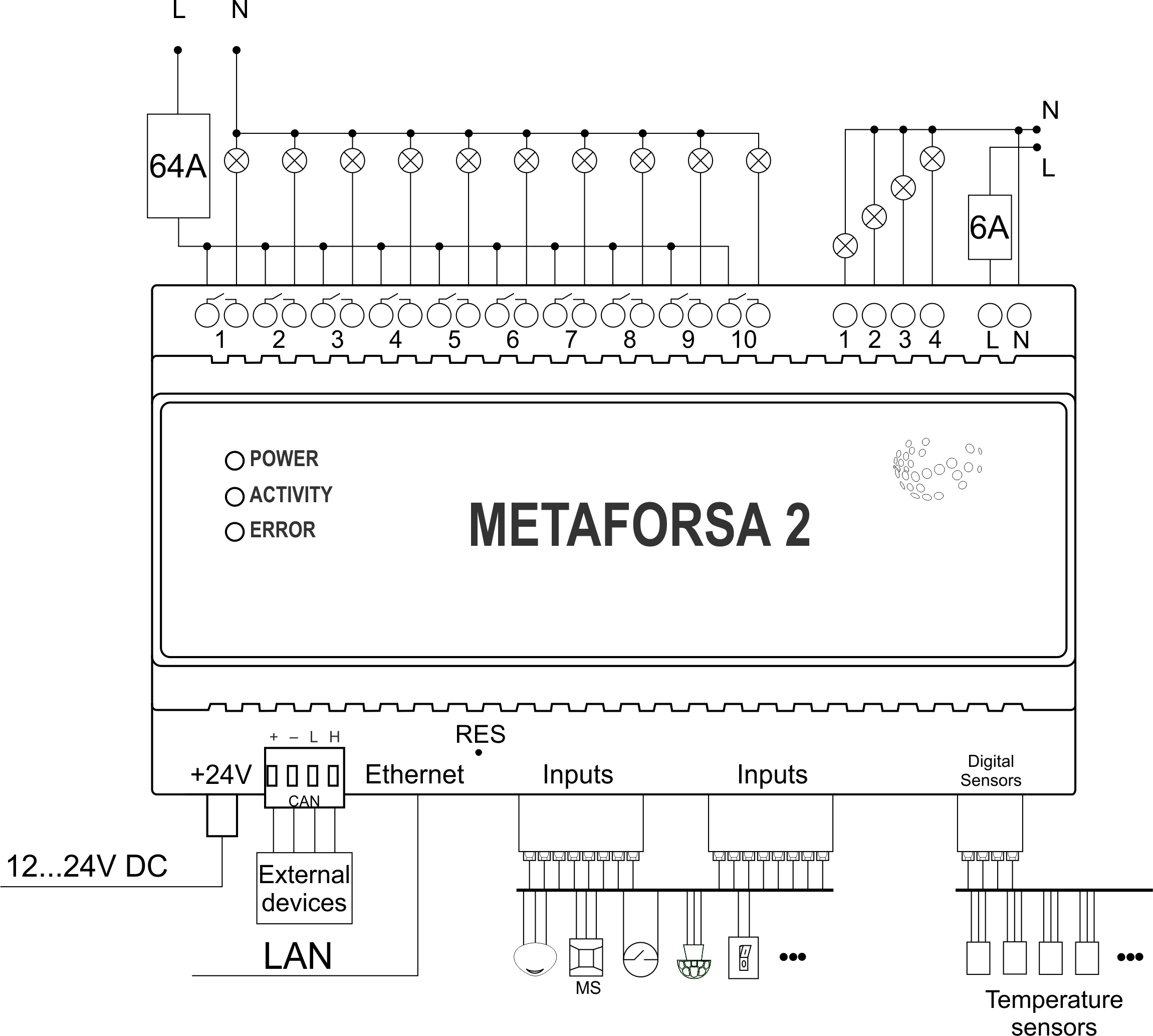
Connection of the actuators
Connection of the lights/electric contactor/heating thermal actuator
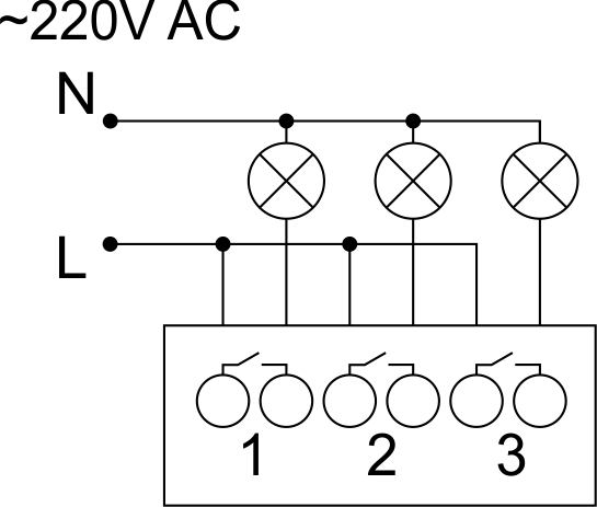 Fig. 4 |
Such actuators as light, electric contactor, heating thermal actuator should be switched on any of the outputs 1 – 10, the neutral wire and the ground wire should be connected directly to the switchboard. The example of connection is shown in Fig.4. |
Connection of high load device
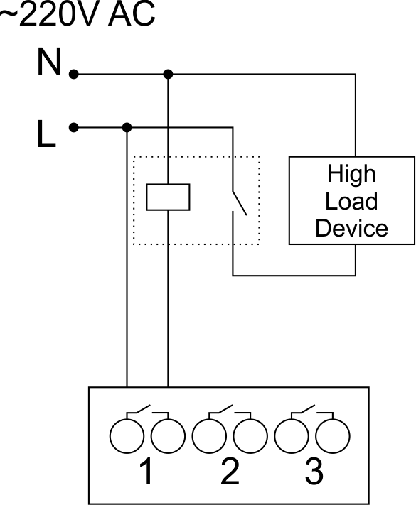 |
Recomended contactors:
|
Connection of single-pole water/gas supply valve
| Caution: Before applying power to the load, make sure that the output configuration of METAFORSA module is correct. The incorrect configuration or incorrect connection can cause the module failure and/or failure of the equipment connected to it, and even a fire. | |
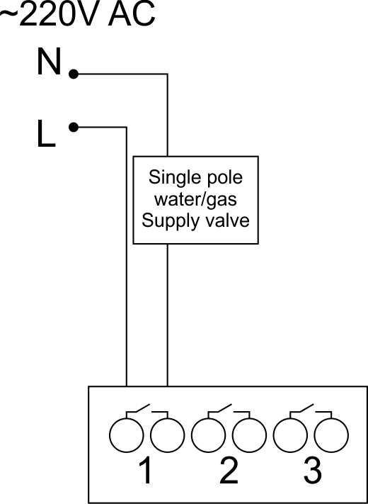 Fig. 5 |
The single pole water/gas supply valve is connected to any of the outputs of 1 – 10, the (neutral wire and the ground wire are connected directly to the switchboard. The example of connection is shown in Fig.5. |
Connection of double-pole water/gas supply valve
| Caution: Before applying power to the valve, it is necessary to ensure the output configuration of METAFORSA module is correct. The incorrect configuration can cause the voltage application simultaneously to both channels of the valve, which may result in the module failure and/or failure of the equipment connected to it, and even a fire. | |
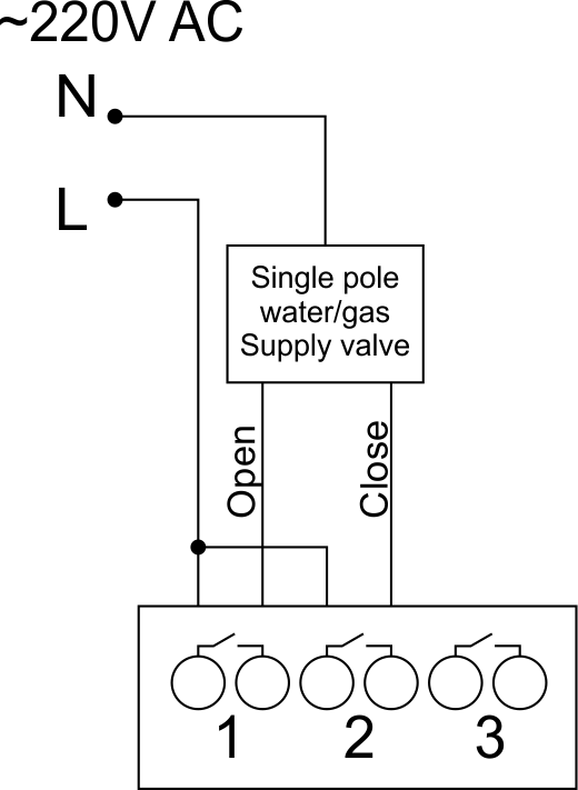 Fig. 6 |
Two adjacent contact points (for example, 3, 4) are used to connect the double-pole water/gas supply valve; in these conditions the neutral wire and the ground wire are connected directly to the switchboard. The example of connection is shown in Fig.6. |
Connection of single-pole gate actuator
| Caution: Before applying power to the module, you should properly configure access to the application. The contacts incorrectly configured can result in the module failure and/or failure of the equipment connected to it, and even a fire.
| |
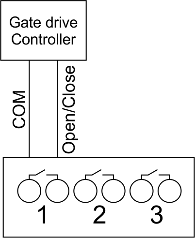 Fig. 7 |
Any contact point (for example, 3) is used to connect the single-pole gate drive controllers. The example of connection is shown in Fig.7. |
Connection of double-pole gate actuator
| Caution: Before applying power to the module, you must properly configure the outputs in the application. The contacts configured incorrectly can lead to simultaneous power supply to both channels, resulting in the module failure and/or failure of the equipment connected to it, and even a fire.
| |
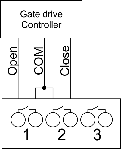 Fig. 8 |
Two adjacent contact points (for example, 3, 4) should be used to connect the double-pole gate drive controller. The example of connection is shown in Fig.8. |
Connection of curtain/jalousie/shutter actuator with 220V force control
| Caution: Before applying power to the module, you must properly configure the outputs in the application. The contacts configured incorrectly can lead to simultaneous power supply to both channels, resulting in the module failure and/or failure of the equipment connected to it, and even a fire.
| |
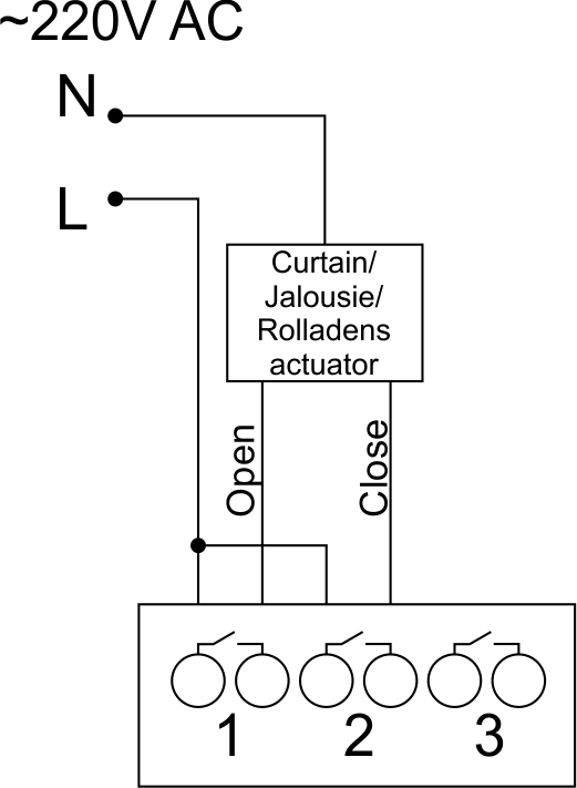 Fig. 9 |
Two adjacent contact points (for example, 3, 4) should be used to connect the curtain/jalousie/rolladens actuator, in these conditions the neutral wire and the ground wire are connected directly to the switchboard. The example of connection is shown in Fig.9. |
Connection of curtain/jalousie/shutter actuator with low-voltage control
| Caution: Before applying power to the module, you must properly configure the outputs in the application. The contacts configured incorrectly can lead to simultaneous power supply to both channels, resulting in the module failure and/or failure of the equipment connected to it, and even a fire.
| |
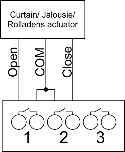 Fig. 10 |
Two adjacent contact points (for example, 3, 4) should be used to connect the curtain/jalousie/rolladens actuator with low-voltage control. The example of connection is shown in Fig.10. |
Connection of sensing elements/switches/buttons
Connection of motion sensors
The motion sensors should be connected to any free input in1-in24; in these conditions their power is connected to the contact points of +12V and GND of the relevant group. The example of connection is shown in Fig.11.
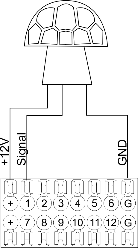
Fig. 11
Connection of FW-WL.A leakage sensors
FW-WL.A leakage sensors are connected to any free input in1 – in24, in these conditions the power should be connected to +12V and GND points of the relevant group. The example of connection is shown in fig. 12.
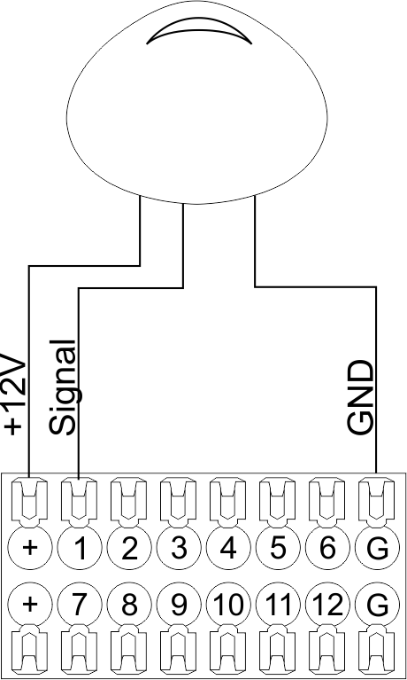 Fig12 |
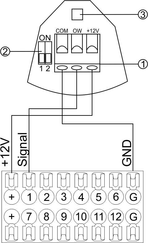 Fig13 |
Configuration and connection of the FW-WL.A sensor 1. Terminals:
- +12V — sensor power is connected to the contact point of METAFORSA “+12V”;
- OW — sensor pickup signal;
- GND — common, connected to GND contact of METAFORSA.
2. Sensor preset switch (optionally):
- 1 — sensor sensitivity (ON – high, OFF – low);
- 2 — indicator colour setting (ON – blue, OFF – green).
3. LED status indicator.
Connection of buttons/switches/magnetic reed switches
Buttons and reed switches are connected to any free input in1-in16, while their second contact point is connected to GND point of the relevant METAFORSA module group, + 12V power outputs – not in use. The example of connection is shown in Fig. 14-16.
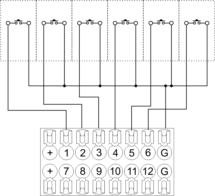 Fig14 connection of buttons/switching units |
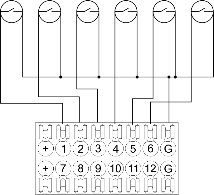 Fig15 connection of the magnetic reed switches (window/door position sensors) |
Connection of digital sensors
The OW adapter (Fig. 16a) is supplied along with METAFORSA module with the possibility to connect up to 8 digital sensors to it. In these conditions, several devices can be connected to one channel (Fig. 16b). The connected sensors are detected automatically and do not require any original setting.
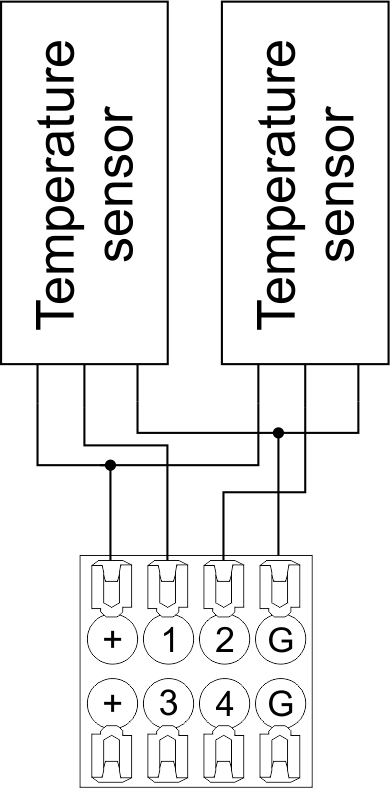 Fig16 a |
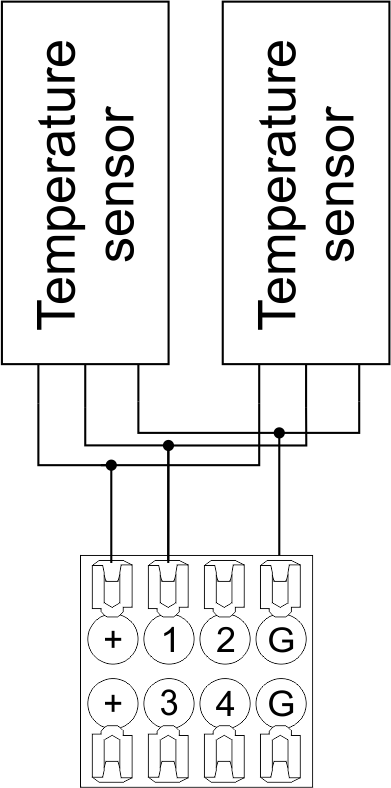 Fig16 b |
Configuration and connection of the OW adapter
Connection of auxiliary equipment.
Expansion modules include Larnitech equipment connected through the CAN-bus. Such equipment includes: dimmers, RGB-backlit control modules, multimode sensors, etc. The equipment connected to the expansion port is defined automatically and does not require any preset tuning. Connector contact pin assignment is defined in Table 4. The example of connection is shown in Fig. 17.

|
| Caution! The 120 ohm terminating resistors should be installed at the end connectors between L and H contact points of CAN-bus. Ensure the connection is correct. The incorrect connection may cause sensor and/or module malfunction. |
Module installation and connection procedure
- Install the module in the switchboard on the DIN-rail and fix it with the special latch on the module base.
- Fasten the supply unit on the left side of the module.
- Connect the connector (4) having the noise filter pre-installed which is supplied complete with the module.
- Connect the connectors (5), (6).
- Connect the connectors (1), (2).
- Connect the connector (3).
- Apply power to the supply unit of METAFORSA module.
- Wait until the module is loaded, then configure it in accordance with the System Setup Instructions.
- Apply power to the connectors (1), (2).
- Check all equipment for proper operation.
METAFORSA module shut-off and deinstallation procedure
- De-energize the module by disconnecting the circuit breaker assembly of the load power supply and METAFORSA module supply unit. Verify the voltage is absent on the terminals (1), (2) of the connector wires and on the input terminals of the supply unit.
- Disconnect the load power supply connectors (1), (2).
- Disconnect the connector (3).
- Disconnect the connectors (4)-(6).
- Remove the module from the DIN-rail, releasing the latch at the bottom of the module base.
Hardware setup
To configure and control METAFORSA SMART HOUSE, you must install Larnitech software on your smartphone or tablet, which is available in App Store and Play Market. After installation, follow the System Setup Instructions.
Fault diagnostics and handling
The following are some possible faults and ways of fault handling. If you have any difficulty, or face the fault undeclared here, please contact the Technical Support: [1] or [support@larnitech.com]. There are also some tips in the FAQ section at our website [2].
The actuators do not operate:
- ensure the outputs are properly configured in the application (see System Setup Instructions);
- check the connection is correct in accordance with table 2 and paragraph 3.6;
- ensure the power is supplied to the input power contact , i.e. all circuit breaker assembly are ON.
- verify the operability of the connected equipment.
The module is off, indication absent:
- check the connection to 24V supply unit as shown in table 2 (contacts pin assignment);
- check the connection of the supply unit to 220V power mains, the indicator should be ON.
Network connection fault:
- ensure the Ethernet cable is properly wired and connected to the connector;
- ensure the LED status indicators are ON on the Ethernet connector;
- check the LAN configuration is correct, Ethernet cable loops are absent;
- METAFORSA module and the device you are connecting from are in the same network.
hold integer 0-10000 1-10 by default hold is the same as runtime hold is the bridging time in miliseconds, is used for gate and jalousie, lock; Example: hold=3500
The sensors do not operate:
- ensure the inputs are properly configured in the application (System Setup Instructions);
- check the connection is correct in accordance with table 2 and paragraph 3.7;
- ensure the METAFORSA module is ON: circuit breaker assembly is closed, indication on the supply unit is ON, the module indication corresponds to the operating status – table 3;
- check the power supply availability on the sensors;
- check the integrity of lines laid to the sensors.
The auxiliary equipment does not operate:
- check the connection is correct in accordance with table 2 and paragraph 3.8-9;
- ensure the METAFORSA module is ON: circuit breaker assembly is closed, indication on the supply unit is ON, the module indication corresponds to the operating status – table 3;
- check the integrity of the CAN lines, voltage supply on the modules.
HW Settings
| Name | Type, range | SUBID | Default | Description |
|---|---|---|---|---|
| runtime | integer 0-100 | 1-10 | 15 | runtime is the open/close time in seconds, is used for jalousie, gate, valve(2 pole);
|
| runtimeopen | integer 0-60000 | Blinds subId | Runtimeopen is the open time in milliseconds, is used for blinds; Example: runtimeopen=15000 | |
| runtimeclose | integer 0-60000 | Blinds subId | Runtimeclose is the close time in milliseconds, is used for blinds; Example: runtimeclose=15000 | |
| hold | integer 0-10000 | 1-10 | 500 | hold is the bridging time in milliseconds, is used for gate and jalousie (by default hold is the same as runtime for jalousie and gate), lock; Example: hold=3500 |
| def | string 'ON' | 1-10 | 'OFF' | def is the element status is set after restart, is used for lamp, heating, valve(1 pole); Example: def='ON' |
| stop | Char ‘R’ | 1-7 | – | (for 2-pole gate and blinds) If it is declared then by Stop command during the motion, the same impulse appears as it was at the beginning of the motion. Pole, an which the stop-impules is formed, is defined by the parameter Stop value. If it is ‘r’ or ‘R’ then stop-impulse is produced on the opposite to the start-impulse pole. If any other value is delcared (e.g., ‘d’ ) then the stop-impulse is on the same pole. If a Runtime passed after the beginning of the motion then the stop-impulse is not formed. Example: stop=’r’ |
| out | char[10] | 98 | 'LLLLHHHHP-' | Each char is responsible for the type of a particular channel
Example: out='LLB-G-V-W-' |
| dm | char[4] | 98 | ‘LLLL’ | Each char is responsible for the type of a particular channel
Example: dm=’skl-‘ |
| def | integer 0-250 | 11-14 | 100 | The default brightness level in case of a power reset (1..250). Example: def=250 |
| min | integer 0-100 | 11-14 | 0 | Minimum dimming level, example: min=10 |
| max | integer 0-100 | 11-14 | 100 | Maximum dimming level, example max=95 |
| start | integer 0-100 | 11-14 | 0 | The Start function is used for lamps that lack the minimal voltage to get turned on. If the set value is lower than the start value, the lamp is turned on at the start value and them the light is dimmed down to the set level. Example: start=60 |
| force | integer 0-100 | 11-14 | 10 | Time duration of the starting value (measured in milliseconds). Example: force=20 |
| runtime | integer 0-60000 | 11-14 | 1000 | Runtime is the speed of changing the brightness from ‘min’ to ‘max’ (measured in milliseconds). Example: runtime=1000 |
| offset | integer (+/- 0…39) | 39-46 | '0' | sensor values offset; For example, offset is -3.8 :
Example: hw="offset='-3.8'" |
| in | char[24] | 98 | 'BBBBBBBBBBBBMMMLLLKKKKKK' | Each char is responsible for the type of a particular channel
Example: in='MMMMMMMMMMMMLLLLLLLLLLLL' 12 motion sensors and 12 leak-sensors; in='BBBBBBBBSSSSSSRRRRSSRRRR' 8 buttons; 8 switches and 8 LED channels. |
 1<item addr="339:1" auto-period="600" cfgid="40" hw="def='ON'" name="Lamp" type="lamp" uniq_id="3779">
 2<item addr="339:2" cfgid="40" hw="def='ON'" name="Radiator" type="valve-heating" uniq_id="3780">
 3    <automation name="Eco" temperature-level="16" uniq_id="3781"/>
 4    <automation name="Comfort" temperature-level="22" uniq_id="3782"/>
 5    <automation name="Hot" temperature-level="25" uniq_id="3783"/>
 6</item>
 7<item addr="339:3" cfgid="40" hw="runtime=9" name="Jalousie" sub-type="120" type="jalousie" uniq_id="32"/>
 8<item addr="339:5" cfgid="40" hw="runtime=13" name="Gate" sub-type="120" type="gate" uniq_id="3784"/>
 9<item addr="339:7" cfgid="40" hw="hold=4600" name="Gate" sub-type="120" type="gate" uniq_id="3785"/>
10<item addr="339:8" cfgid="40" hw="runtime=10" name="Valve" type="valve" uniq_id="3786"/>
11<item addr="339:11" cfgid="40" name="Motion" type="motion-sensor" uniq_id="17"/>
12<item addr="339:12" cfgid="40" name="Motion" type="motion-sensor" uniq_id="18"/>
13<item addr="339:13" cfgid="40" name="Motion" type="motion-sensor" uniq_id="19"/>
14<item addr="339:16" cfgid="40" name="Leak" type="leak-sensor" uniq_id="21"/>
15<item addr="339:17" cfgid="40" name="Leak" type="leak-sensor" uniq_id="41"/>
16<item addr="339:19" cfgid="40" name="Switch" type="switch" uniq_id="22"/>
17<item addr="339:20" cfgid="40" name="Switch" type="switch" uniq_id="23"/>
18<item addr="339:21" cfgid="40" name="Switch" type="switch" uniq_id="24"/>
19<item addr="339:22" cfgid="40" name="Switch" type="switch" uniq_id="25"/>
20<item addr="339:23" cfgid="40" name="Door" type="door-sensor" uniq_id="26"/>
21<item addr="339:24" cfgid="40" name="Door" type="door-sensor" uniq_id="27"/>
22<item addr="339:25" cfgid="40" name="Door" type="door-sensor" uniq_id="28"/>
23<item addr="339:26" cfgid="40" name="Door" type="door-sensor" uniq_id="29"/>
24<item addr="339:30" cfgid="40" name="Temperature" type="temperature-sensor" uniq_id="3772"/>
25<item addr="339:31" cfgid="40" name="Temperature" type="temperature-sensor" uniq_id="3773"/>
26<item addr="339:32" cfgid="40" name="Temperature" type="temperature-sensor" uniq_id="3774"/>
27<item addr="339:33" cfgid="40" hw="offset='-10.8'" name="Temperature" type="temperature-sensor" uniq_id="3775"/>
28<item addr="339:34" cfgid="40" hw="offset='25.1'" name="Temperature" type="temperature-sensor" uniq_id="3776"/>
29<item addr="339:35" cfgid="40" name="Temperature" type="temperature-sensor" uniq_id="3777"/>
30<item addr="339:36" cfgid="40" name="Temperature" type="temperature-sensor" uniq_id="3778"/>
31<item addr="339:98" cfgid="40" hw="out='LHB-G-XV--' in='MMM--LL-BBBBKKKK'" name="Temperature" system="yes" type="temperature-sensor" uniq_id="30"/>