Difference between revisions of "DW-DM04/ru"
(Created page with "<div class="caution"> ВНИМАНИЕ! Все работы, связанные с установкой, подключением, настройкой, обслуживан...") |
(Created page with "==Изображение модуля==") |
||
| Line 47: | Line 47: | ||
</div> | </div> | ||
| − | == | + | ==Изображение модуля== |
[[File:DM04C VIEW.png|500px]] | [[File:DM04C VIEW.png|500px]] | ||
Revision as of 11:11, 6 January 2022
| DW-DM04.C | |||||||||
|---|---|---|---|---|---|---|---|---|---|
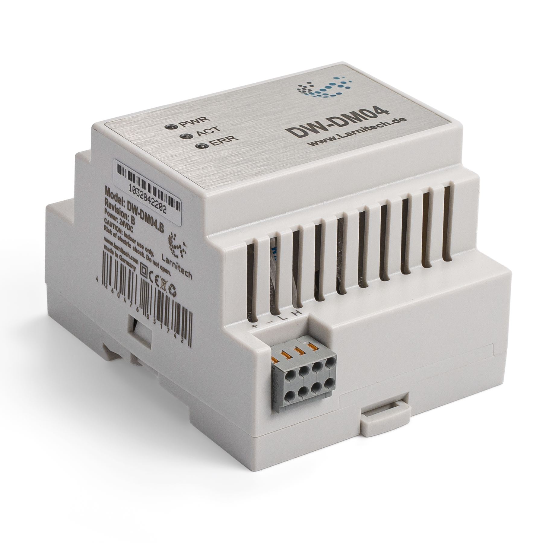 | |||||||||
| |||||||||
4-Х КАНАЛЬНЫЙ ДИММЕР
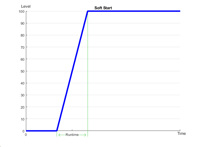
Этот модуль предназначен для плавной регулировки яркости осветительных приборов (не реактивной нагрузки). Тип диммера MOSFET, диммирование по заднему фронту. Как и все устройства Larnitech, диммер автоматически обнаруживается и настраивается при добавлении в систему. В диммере есть собственный логический модуль, выполняющий скрипты из базы обширной и постоянно пополняемой базы данных Larnitech для осуществления управления на основе распределённой логики, что гарантирует надёжность его работы. Расширенные установки работы светодиодных светильников обеспечивают более точную настройку, а режим мягкого включения увеличивает срок службы электроламп, дополнительно предоставляя комплексную защиту по ряду параметров.
Функции
- Нагрузка резистивного или ёмкостного типа на 4 канала. Каждый канал выдерживает до 500 Вт
- Работает с галогеновыми/светодиодными лампами
- Расширенные настройки управления светодиодными лампами
- Режим плавного включения ламп
- Защита от перегрузки
- Защита от перегрева
- Защита от короткого замыкания
- Plug and Play (модуль автоматически обнаруживается и настраивается системой при подключении)
- Встроенный логический блок
- Регулярные обновления системы
ВНИМАНИЕ! Все работы, связанные с установкой, подключением, настройкой, обслуживанием и поддержкой оборудования, должны выполняться только квалифицированным персоналом, обладающим достаточными навыками и опытом работы с электрооборудованием! Во избежание риска возгорания, поражения электрическим током, повреждения системы и/или травм, установка и сборка системы должны выполняться в соответствии с указаниями, перечисленными ниже:
- все работы по подключению должны выполняться при выключенном питании;
- необходимо использовать соответствующие инструменты и средства индивидуальной защиты от поражения электрическим током;
- запрещается использовать поврежденные кабели, провода и разъемы;
- избегайте перегиба проводов и кабелей;
- не прилагайте чрезмерных усилий к проводам путем их перегиба или слишком сильного сжатия: внутренние проводники кабелей и проводов могут быть оголены или повреждены;
- не используйте для подключения разъемы с плохими контактами;
- не превышайте параметры предельной нагрузки, указанные в инструкции;
- сечение питающих проводов зависит от требований к пределу плотности тока, типу изоляции и материалу проводов. Недостаточное сечение провода может привести к перегреву кабеля и возгоранию.
Когда питание включено, НИКОГДА:
- не подключайте/отключайте разъемы;
- не открывайте модули и датчики.
Изображение модуля
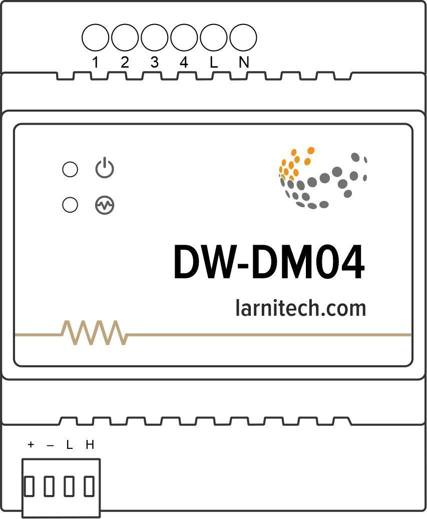
Example of connection
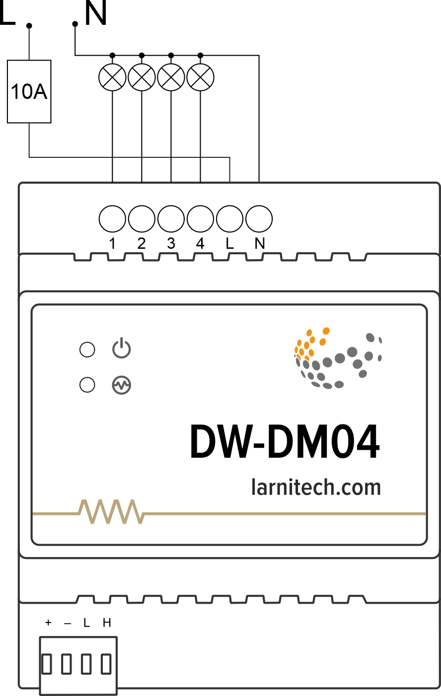
Module dimensions
Internal layout
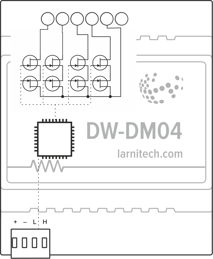
Module parameters
| Parameter name | Value |
|---|---|
| Dimming channels qty | 4 |
| Input voltage | 100-240V AC, 50-60 Hz |
| Current type | AC |
| Max load per channel | 2.27A (500W at 220V) |
| Max load per device | 7.27A (1600W at 220V) |
| Dimmer type | MOSFET |
| Dimming type | trailing edge |
| Power supply | 11.5 … 27.5 V DC from CAN |
| Max current(24V) | 35 mA |
| Bus type | CAN (4-wire) |
| Equipment installation type | DIN rail (EN 60715) |
| Case material | ABS |
| Protection | IP40 |
| Temperature range | -10 … +50 °C |
| Size | 4U, 69x102x58 mm |
| Weight | 180 g |
Supported load types
| Supported load type | Power | |
|---|---|---|
 |
Conventional incandescent lamps | 0-500W |
 |
Halogen light sources | 0-500W |
 |
LED lamps with dimming support | 0-500W |
 |
Energy saving lamps with dimming support | 0-500W |
 |
Electronic ballasts with dimming support | 0-500W |
Indication of module operation
Bootloader
| Indicator | Status | Description |
|---|---|---|
| Device in bootloader | ||
| Waiting for bootloader command | ||
| Flashing firmware |
Firmware
| Indicator | Status | Description |
|---|---|---|
| Identification | ||
| Operational mode | ||
Error | ||
| Lost connection to server | ||
| Overheat | ||
| No AC power | ||
| RTC error |
Module installation and connection procedure
- Install the module in the switchboard on the DIN rail and fix it with the special latch on the module base.
- Connect the CAN connector.
- Connect the contacts (1-4).
- Configure the module using LT setup.
- Apply power to the load.
- Check all equipment for proper operation.
Module shut-off and deinstallation procedure
- Disconnect the power from the load.
- Disconnect the contacts (1-4).
- Disconnect the CAN connector.
- Remove the module from the DIN rail, releasing the latch at the bottom of the module base.
Dimmer workflow
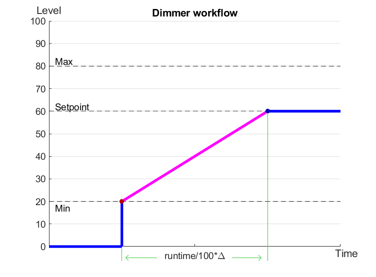
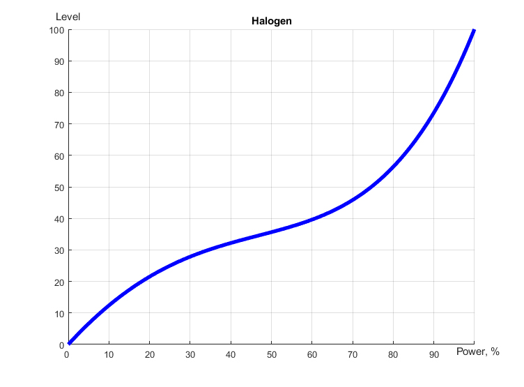
Linear, LED and Halogen workflows
HW settings
| Name | Type, range | SUBID | Default | Description |
|---|---|---|---|---|
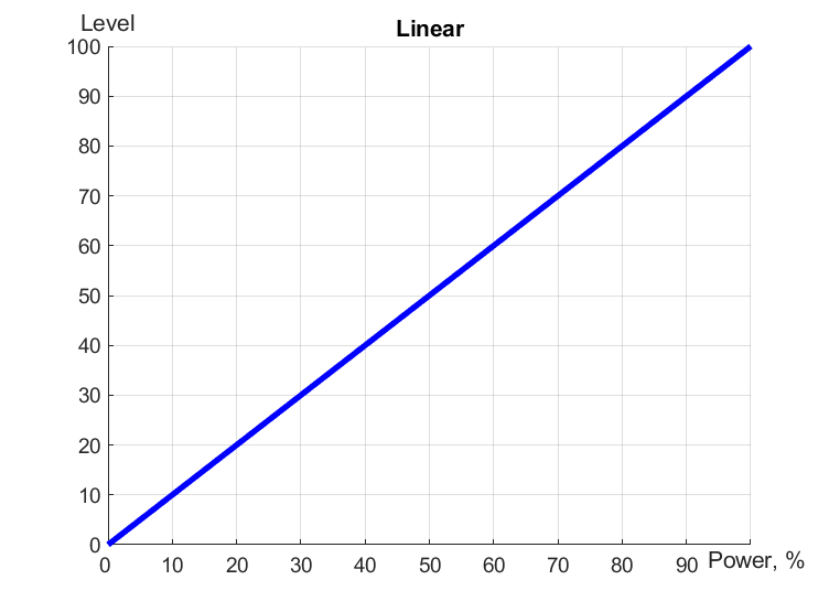
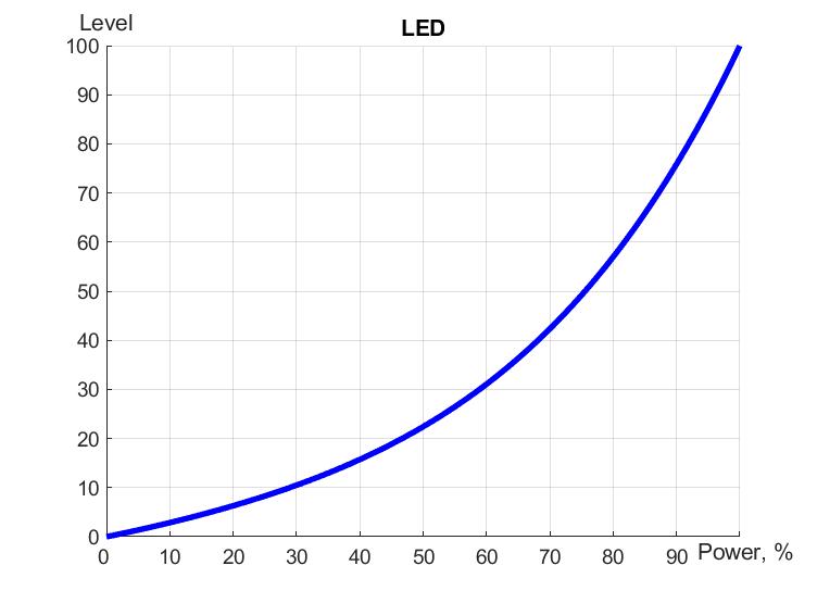
| dm | char[4] | 98 | 'LLLL' | Each char is responsible for the type of a particular channel
Example: dm='skl-' |
| def | integer 0-250 | 1-4 | 100 | The default brightness level in case of a power reset (1..250). Example: def=250 |
| min | integer 0-100 | 1-4 | 0 | Minimum dimming level, example: min=10 |
| max | integer 0-100 | 1-4 | 100 | Maximum dimming level, example max=95 |
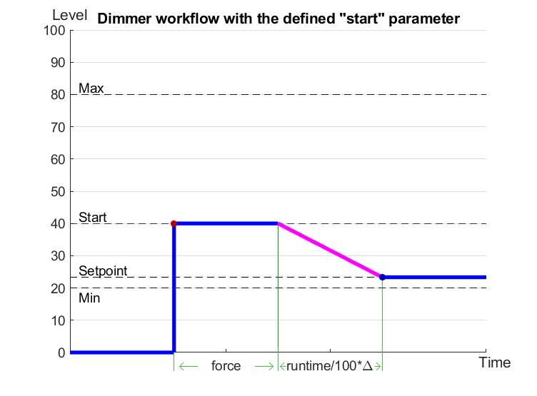
| start | integer 0-100 | 1-4 | 0 | The Start function is used for lamps that lack the minimal voltage to get turned on. If the set value is lower than the start value, the lamp is turned on at the start value and them the light is dimmed down to the set level. Example: start=60 |
| force | integer 0-100 | 1-4 | 10 | Time duration of the starting value (measured in milliseconds). Example: force=20 |
| runtime | integer 0-60000 | 1-4 | 1000 | Runtime is the speed of changing the brightness from 'min' to 'max' (measured in milliseconds). Example: runtime=1000 |
1<item addr="307:1" auto-period="600" cfgid="77" hw="def=200 min=30 max=88 start=35 force=20 runtime=1000 " name="Dimmer" type="dimer-lamp" uniq_id="51"/>
2<item addr="307:2" auto-period="600" cfgid="77" hw="min=20 max=90 " name="Dimmer" type="dimer-lamp" uniq_id="52"/>
3<item addr="307:3" auto-period="600" cfgid="77"  name="Dimmer" type="dimer-lamp" uniq_id="53"/>
4<item addr="307:97" cfgid="77" name="Temperature" system="yes" type="temperature-sensor" uniq_id="55"/>
5<item addr="307:98" cfgid="77" hw="dm='++--'" name="Temperature" system="yes" type="temperature-sensor" uniq_id="56"/>