Difference between revisions of "Translations:Metaforsa2 MF-14/29/en"

From Larnitech wiki page
Jump to navigation Jump to search
(Importing a new version from external source)
 
(Importing a new version from external source)
 
Line 18: Line 18:
 
|[[File:OW.png|80px|frameless]] ||OneWire|| Digital sensors connection (temperature)<br>VCC — sensors power supply output +5V<br>OW1-OW4 — OneWire data buses<br>GND — common
 
|[[File:OW.png|80px|frameless]] ||OneWire|| Digital sensors connection (temperature)<br>VCC — sensors power supply output +5V<br>OW1-OW4 — OneWire data buses<br>GND — common
 
|-
 
|-
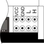
|[[File:Can.jpg|80px|frameless]] ||VCC<br>GND<br>L<br>H|| External modules connection for CAN-bus<br>VСС — 12V output for external devices power supply<br>GND — common<br>L — CAN-L data bus<br>H — CAN-H data bus
+
|[[File:Can.jpg|80px|frameless]] ||VCC<br>GND<br>L<br>H|| External modules connection for CAN-bus<br>VСС — 24V output for external devices power supply<br>GND — common<br>L — CAN-L data bus<br>H — CAN-H data bus
 
|}
 
|}

Latest revision as of 14:50, 8 February 2024

Information about message (contribute)
This message has no documentation. If you know where or how this message is used, you can help other translators by adding documentation to this message.
Message definition (Metaforsa2 MF-14)
{| class="wikitable"
|+ text-align="left"|'''Table2'''
|-
!Connector!!Contact!!Assignment
|-
|[[File:Out.png|80px|frameless]] ||1-10|| Load application (light lamps, thermal actuators, etc.)
|-
|[[File:Dimm.png|80px|frameless]] ||D1-4, L, N|| Load application (dimming lamps)
|-
| colspan="2"| Device status indicators || The module status indicators are described in '''table 3'''
|-
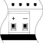
|[[File:24vconn.png|80px|frameless]] ||+24V<br>GND|| +24V — module power supply by an external 24 V power supply GND — common
|-
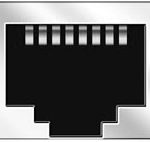
|[[File:Rj45.jpg|80px|frameless]] ||RJ45|| Connector for LAN connectivity
|-
|[[File:Inputs.png|80px|frameless]] ||In1-12, In13-24 GND|| Controlling devices connection (buttons, magnetic reed switches, motion or leakage sensors): +12V — sensor power output +12 V<br>In1 … In24 — logic inputs (0-12 V)<br>GND — common
|-
|[[File:OW.png|80px|frameless]] ||OneWire|| Digital sensors connection (temperature)<br>VCC — sensors power supply output +5V<br>OW1-OW4 — OneWire data buses<br>GND — common
|-
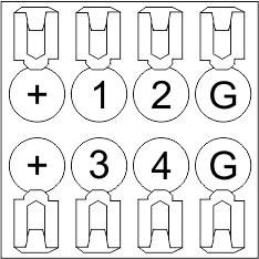
|[[File:Can.jpg|80px|frameless]] ||VCC<br>GND<br>L<br>H|| External modules connection for CAN-bus<br>VСС — 24V output for external devices power supply<br>GND — common<br>L — CAN-L data bus<br>H — CAN-H data bus
|}
Translation{| class="wikitable"
|+ text-align="left"|'''Table2'''
|-
!Connector!!Contact!!Assignment
|-
|[[File:Out.png|80px|frameless]] ||1-10|| Load application (light lamps, thermal actuators, etc.)
|-
|[[File:Dimm.png|80px|frameless]] ||D1-4, L, N|| Load application (dimming lamps)
|-
| colspan="2"| Device status indicators || The module status indicators are described in '''table 3'''
|-
|[[File:24vconn.png|80px|frameless]] ||+24V<br>GND|| +24V — module power supply by an external 24 V power supply GND — common
|-
|[[File:Rj45.jpg|80px|frameless]] ||RJ45|| Connector for LAN connectivity
|-
|[[File:Inputs.png|80px|frameless]] ||In1-12, In13-24 GND|| Controlling devices connection (buttons, magnetic reed switches, motion or leakage sensors): +12V — sensor power output +12 V<br>In1 … In24 — logic inputs (0-12 V)<br>GND — common
|-
|[[File:OW.png|80px|frameless]] ||OneWire|| Digital sensors connection (temperature)<br>VCC — sensors power supply output +5V<br>OW1-OW4 — OneWire data buses<br>GND — common
|-
|[[File:Can.jpg|80px|frameless]] ||VCC<br>GND<br>L<br>H|| External modules connection for CAN-bus<br>VСС — 24V output for external devices power supply<br>GND — common<br>L — CAN-L data bus<br>H — CAN-H data bus
|}
Table2
Connector Contact Assignment
Out.png 1-10 Load application (light lamps, thermal actuators, etc.)
Dimm.png D1-4, L, N Load application (dimming lamps)
Device status indicators The module status indicators are described in table 3
24vconn.png +24V
GND
+24V — module power supply by an external 24 V power supply GND — common
Rj45.jpg RJ45 Connector for LAN connectivity
Inputs.png In1-12, In13-24 GND Controlling devices connection (buttons, magnetic reed switches, motion or leakage sensors): +12V — sensor power output +12 V
In1 … In24 — logic inputs (0-12 V)
GND — common
OW.png OneWire Digital sensors connection (temperature)
VCC — sensors power supply output +5V
OW1-OW4 — OneWire data buses
GND — common
Can.jpg VCC
GND
L
H
External modules connection for CAN-bus
VСС — 24V output for external devices power supply
GND — common
L — CAN-L data bus
H — CAN-H data bus