BW-IO
From Larnitech wiki page
Jump to navigation
Jump to search
| BW-IO.C |
|---|
 |
|
| Number of switched channels | 3 |
|---|
|
|
|
| Supply voltage | 11.5...27.5 V DC |
|---|
| Dimentions | 45x42x14 mm |
|---|
|
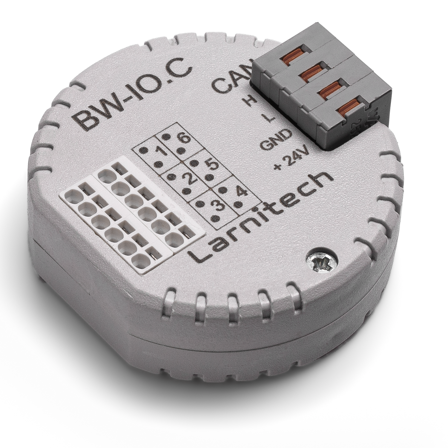
6-ТИ КАНАЛЬНЫЙ МОДУЛЬ ВХОДОВ/ВЫХОДОВ
Модуль предназначен для подключения сторонних цифровых
устройств, которые не имеют стандартных интерфейсов
ВНИМАНИЕ! Все работы, связанные с установкой, подключением, настройкой, обслуживанием и поддержкой оборудования, должны выполняться только квалифицированным персоналом, обладающим достаточными навыками и опытом работы с электрооборудованием! Во избежание риска возгорания, поражения электрическим током, повреждения системы и/или травм, установка и сборка системы должны выполняться в соответствии с указаниями, перечисленными ниже:
- все работы по подключению должны выполняться при выключенном питании;
- необходимо использовать соответствующие инструменты и средства индивидуальной защиты от поражения электрическим током;
- запрещается использовать поврежденные кабели, провода и разъемы;
- избегайте перегиба проводов и кабелей;
- не прилагайте чрезмерных усилий к проводам путем их перегиба или слишком сильного сжатия: внутренние проводники кабелей и проводов могут быть оголены или повреждены;
- не используйте для подключения разъемы с плохими контактами;
- не превышайте параметры предельной нагрузки, указанные в инструкции;
- сечение питающих проводов зависит от требований к пределу плотности тока, типу изоляции и материалу проводов. Недостаточное сечение провода может привести к перегреву кабеля и возгоранию.
Когда питание включено, НИКОГДА:
- не подключайте/отключайте разъемы;
- не открывайте модули и датчики.
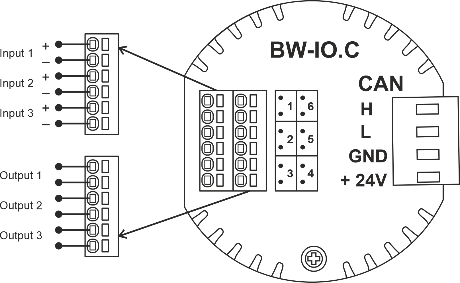
Пример подключения
Параметры модуля
| Parameter name |
Value
|
| Input channels qty |
3
|
| Input/output channels qty |
|
| 0-10 input port quantity |
|
| Buttons |
|
| LED Buttons |
|
| Number of sensor inputs |
|
| Number of dry contact inputs |
|
| RS485 ports qty |
|
| RS232 ports qty |
|
| UART ports qty |
|
| M-BUS port quantity |
|
| Pulse inputs quantity |
|
| DALI ports qty |
|
| DALI-line voltage supply |
|
| Peak current of DALI-line power supply |
|
| Peak current in DALI-line |
|
| Maximum DALI devices quantity |
|
| Dimming channels qty |
|
| Output channels qty |
3
|
| 0-10 output port quantity |
|
| Analog output channels qty |
|
| Output |
|
| Digital line maximum length |
|
| Discrete input channels qty |
|
| Digital input channels qty |
|
| Speakers |
|
| Max power output audio channel |
|
| Camera |
|
| IR lighting |
|
| Card reader |
|
| Connection type |
|
| Protocols |
|
| Backlight voltage |
|
| Load type |
|
| Dimmer load type |
|
| Supported sensors |
|
| Input voltage |
|
| Current type |
|
| Adjustment type |
|
| Max load |
|
| Min load |
|
| Max load per channel |
|
| Max load per group |
|
| Max load per device |
|
| Control parameters |
|
| Angle of vision IR |
°
|
| Angle of motion |
°
|
| Temperature measuring range |
°C
|
| Humidity measuring range |
|
| Dimmer type |
|
| Dimming type |
|
| Voltage that may be applied to the input channels |
|
| Max output switching voltage |
60V AC/DC
|
| Max output switching current |
50mA
|
| Power supply |
11.5 … 27.5 V DC from CAN
|
| Max current(24V) |
25 mA
|
| Max current(13V) |
|
| Max detection distance |
|
| Max IR distance |
|
| Max BT distance |
|
| Max current |
|
| Relay |
|
| Data transfer speed |
|
| Permissible section of power supply cable to connect in socket: |
|
| Sensors VCC output |
|
| Sensors max VCC current |
|
| R1-R2 inputs max current |
|
| Push-button/reed switches line recommended length |
|
| Temperature sensor line max length |
|
| Sensor cable length |
|
| Sensors line max length |
|
| Bus type |
CAN (4-wire)
|
| Compatible with |
|
| Output voltage |
|
| Output current |
|
| Equipment installation type |
Free
|
| Mounting |
|
| Max cabel lenght |
|
| Case material |
ABS
|
| Protection |
IP40
|
| Temperature range |
-10 … +50 °C
|
| Size |
45x42x14 mm
|
| Weight |
15 g
|
* -
** -
*** -
1 -
2 -
3 -
Module installation and connection procedure
- Connect the outputs.
- Connect the inputs.
- Connect the CAN connector.
- Configure the module using LT setup.
- Check all equipment for proper operation.
Module shut-off and deinstallation procedure
- Disconnect the CAN connector.
- Disconnect the inputs.
- Disconnect the outputs.
HW settings
| Name |
Type, range |
SUBID |
Default |
Description
|
| io |
char[6] |
98 |
'HHHLLL' |
Each char is responsible for the type of a particular channel
- 1-3 channels
- 'H' – Contact
- 'K' – Inverted contact
- 'L' – Backlit button
- 'M' – Inverted backlit button
- 4-6 channels
- 'L'-Lamp
- 'M'-Lamp Inverse;
- 'J'-Heating NO, valve-heating, normally open;
- 'H'-Heating NC, valve-heating, normally closed;
- 'B'-Blinds, jalousie/curtains(2 pole);
- 'C'-Blinds Inverse, jalousie/curtains, invert open-close(2 pole);
- 'G'-Gate (2 pole), 2 pole gate;
- 'D'-Gate (2 pole) Inverse, 2 pole gate, invert open-close;
- 'X'-Gate (1 pole /short press), 1 pole gate;
- 'Z'-Gate (1 pole) Inverse, 1 pole gate, invert open-close;
- 'V'-Valve (2 pole), 2 pole valve,;
- 'W'-Valve (2 pole) Inverse, 2 pole valve, invert open-close;
- 'R'-Valve (1 pole), 1 pole valve;
- 'S'-Valve (1 pole) Inverse, 1 pole valve, invert open-close;
- 'K'-Lock (short press);
- 'N'-Lock (short press) Inverse;
- 'F'-FanCoil. Group1 (Lamp Toggle). For fancoil speed control;
- 'E'-FanCoil. Group2 (Lamp Toggle). For fancoil speed control;
- 'Q'-FanCoil. Group3 (Lamp Toggle). For fancoil speed control;
- 'U'-FanCoil. Group4 (Lamp Toggle). For fancoil speed control;
- 'I'-FanCoil. Group5 (Lamp Toggle). For fancoil speed control;
- '-'-none, nothing is connected.
Example:
|