EW-WL.B
From Larnitech wiki page
Jump to navigation
Jump to search
| EW-WL.B |
|---|
 |
|
| Supply voltage | 9-12 V DC |
|---|
| Dimentions | 18x18x20 mm |
|---|
|
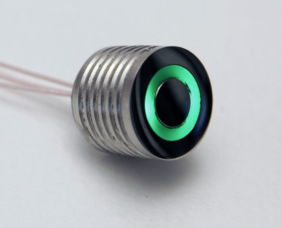
BUILT-IN FLOOR LEAKAGE SENSOR
Water leakage sensor with an alarm light, mountable in the floor
surface. Used together with DW-WL02 or BW-LSA modules.
Features
- Sensor presence detection
- Customizing the indication colors
- Adjusting the sensor sensitivity
- Connections of several sensors to one bus
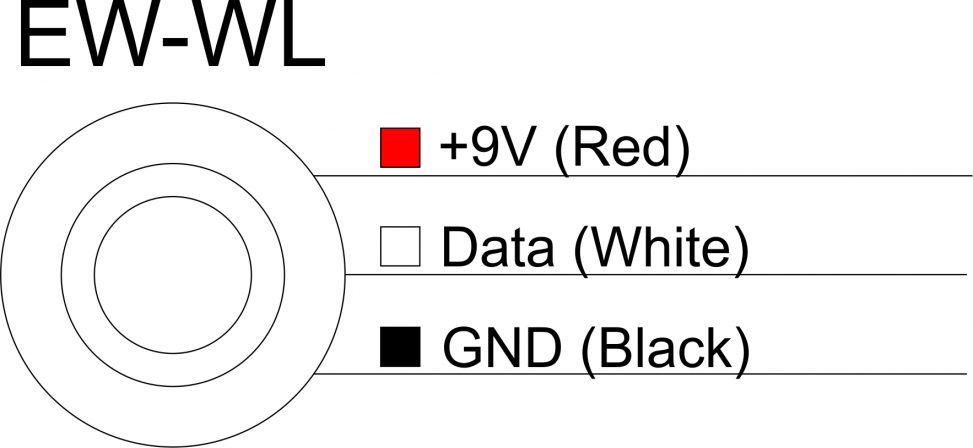
Pin assignment
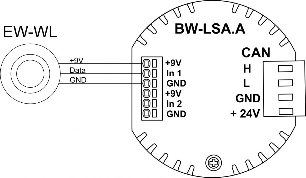
Example of connection
Module parameters
| Parameter name |
Value
|
| Input channels qty |
|
| Input/output channels qty |
|
| 0-10 input port quantity |
|
| Buttons |
|
| LED Buttons |
|
| Number of sensor inputs |
|
| Number of dry contact inputs |
|
| RS485 ports qty |
|
| RS232 ports qty |
|
| UART ports qty |
|
| M-BUS port quantity |
|
| Pulse inputs quantity |
|
| DALI ports qty |
|
| DALI-line voltage supply |
|
| Peak current of DALI-line power supply |
|
| Peak current in DALI-line |
|
| Maximum DALI devices quantity |
|
| Dimming channels qty |
|
| Output channels qty |
|
| 0-10 output port quantity |
|
| Analog output channels qty |
|
| Output |
|
| Digital line maximum length |
|
| Discrete input channels qty |
|
| Digital input channels qty |
|
| Speakers |
|
| Max power output audio channel |
|
| Camera |
|
| IR lighting |
|
| Card reader |
|
| Connection type |
|
| Protocols |
|
| Backlight voltage |
|
| Load type |
|
| Dimmer load type |
|
| Supported sensors |
|
| Input voltage |
|
| Current type |
|
| Adjustment type |
|
| Max load |
|
| Min load |
|
| Max load per channel |
|
| Max load per group |
|
| Max load per device |
|
| Control parameters |
|
| Angle of vision IR |
°
|
| Angle of motion |
°
|
| Temperature measuring range |
°C
|
| Humidity measuring range |
|
| Dimmer type |
|
| Dimming type |
|
| Voltage that may be applied to the input channels |
|
| Max output switching voltage |
|
| Max output switching current |
|
| Power supply |
9-12 V DC
|
| Max current(24V) |
20 mA
|
| Max current(13V) |
|
| Max detection distance |
|
| Max IR distance |
|
| Max BT distance |
|
| Max current |
|
| Relay |
|
| Data transfer speed |
|
| Permissible section of power supply cable to connect in socket: |
|
| Sensors VCC output |
|
| Sensors max VCC current |
|
| R1-R2 inputs max current |
|
| Push-button/reed switches line recommended length |
|
| Temperature sensor line max length |
|
| Sensor cable length |
|
| Sensors line max length |
|
| Bus type |
|
| Compatible with |
MF-10
DW-WL02/HTxx
BW-LSA
|
| Output voltage |
|
| Output current |
|
| Equipment installation type |
Built into the floor
|
| Mounting |
|
| Max cabel lenght |
|
| Case material |
stainless steel
|
| Protection |
IP65
|
| Temperature range |
-10 … +50 °C
|
| Size |
18x18x20 mm
|
| Weight |
20g
|
* -
** -
*** -
1 -
2 -
3 -
HW settings
| Name |
Type, range |
SUBID |
Default |
Description
|
| c0 |
int[4] |
sensors subId |
0;0;255;15 |
Normal state color in format 'red;green;blue;blink'
red, green, blue – 0..255;
blink:
- 0 – pulse
- 1 – blink per 2 seconds
- 2 – blink per second
- 15 – constant glow
Example:
|
| c1 |
int[4] |
sensors subId |
0;0;255;15 |
On-start color in format 'red;green;blue;blink'
red, green, blue – 0..255;
blink:
- 0 – pulse
- 1 – blink per 2 seconds
- 2 – blink per second
- 15 – constant glow
Example:
|
| c2 |
int[4] |
sensors subId |
255;100;0;15 |
'Leak was previously reported' color in format 'red;green;blue;blink'
red, green, blue – 0..255;
blink:
- 0 – pulse
- 1 – blink per 2 seconds
- 2 – blink per second
- 15 – constant glow
Example:
|
| c3 |
int[4] |
sensors subId |
255;0;0;15 |
On-leak color in format 'red;green;blue;blink'
red, green, blue – 0..255;
blink:
- 0 – pulse
- 1 – blink per 2 seconds
- 2 – blink per second
- 15 – constant glow
Example:
|
| sens |
int |
sensors subId |
128 |
Sensor sensitivity
Example:
|
| test |
int(0,1) |
sensors subId |
1 |
0 - Disable the test signal to detect the presence of the sensor
|
- Removing HW does not return the above parameters to their default values.To return to their default values, they must be set explicitly.