(diff) ← Older revision | Latest revision (diff) | Newer revision → (diff)
| BW-SW24V.C |
|---|
 |
|
| Number of switched channels | 6 |
|---|
|
|
| Number of inputs | 6 |
|---|
| Number of buttons | 6 |
|---|
| Number of LED buttons | 6 |
|---|
|
|
| Supply voltage | 11.5...27.5 V DC |
|---|
| Dimentions | 45x42x14 mm |
|---|
|
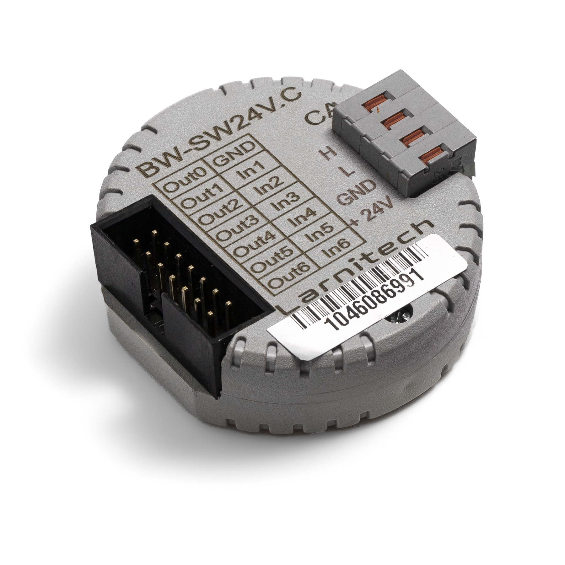
24V BUTTONS INPUT MODULE
This module is used to connect 24V buttons w/wo LED backlighting.
Example of connection
HW example:
1hw="in='BBBBBB' out='BBBBBB' common='A'"
6 common-wire buttons with common-anode 24 V DC LEDs
common='A' – use Out0 as common anode
HW example:
1hw="in='BBBBBB' out='BBBBBB' common='C'"
6 common-wire buttons with common-catode 24 V DC LEDs
common='C' – use Out0 as common catode
Module parameters
| Parameter name |
Value
|
| Input channels qty |
6
|
| Input/output channels qty |
|
| 0-10 input port quantity |
|
| Buttons |
6
|
| LED Buttons |
6
|
| Number of sensor inputs |
|
| Number of dry contact inputs |
|
| RS485 ports qty |
|
| RS232 ports qty |
|
| UART ports qty |
|
| M-BUS port quantity |
|
| Pulse inputs quantity |
|
| DALI ports qty |
|
| DALI-line voltage supply |
|
| Peak current of DALI-line power supply |
|
| Peak current in DALI-line |
|
| Maximum DALI devices quantity |
|
| Dimming channels qty |
|
| Output channels qty |
6
|
| 0-10 output port quantity |
|
| Analog output channels qty |
|
| Output |
|
| Digital line maximum length |
|
| Discrete input channels qty |
|
| Digital input channels qty |
|
| Speakers |
|
| Max power output audio channel |
|
| Camera |
|
| IR lighting |
|
| Card reader |
|
| Connection type |
|
| Protocols |
|
| Backlight voltage |
11.5 … 27.5 V DC (from CAN)
|
| Load type |
|
| Dimmer load type |
|
| Supported sensors |
|
| Input voltage |
|
| Current type |
|
| Adjustment type |
|
| Max load |
|
| Min load |
|
| Max load per channel |
|
| Max load per group |
|
| Max load per device |
|
| Control parameters |
|
| Angle of vision IR |
°
|
| Angle of motion |
°
|
| Temperature measuring range |
°C
|
| Humidity measuring range |
|
| Dimmer type |
|
| Dimming type |
|
| Voltage that may be applied to the input channels |
|
| Max output switching voltage |
|
| Max output switching current |
|
| Power supply |
11.5 … 27.5 V DC from CAN
|
| Max current(24V) |
30 mA
|
| Max current(13V) |
|
| Max detection distance |
|
| Max IR distance |
|
| Max BT distance |
|
| Max current |
|
| Relay |
|
| Data transfer speed |
|
| Permissible section of power supply cable to connect in socket: |
|
| Sensors VCC output |
|
| Sensors max VCC current |
|
| R1-R2 inputs max current |
|
| Push-button/reed switches line recommended length |
|
| Temperature sensor line max length |
|
| Sensor cable length |
|
| Sensors line max length |
|
| Bus type |
CAN (4-wire)
|
| Compatible with |
|
| Output voltage |
|
| Output current |
|
| Equipment installation type |
Free
|
| Mounting |
|
| Max cabel lenght |
|
| Case material |
ABS
|
| Protection |
IP40
|
| Temperature range |
-10 … +50 °C
|
| Size |
45x42x14 mm
|
| Weight |
25 g
|
* -
** -
*** -
1 -
2 -
3 -
Module installation and connection procedure
- Connect the inputs and outputs.
- Connect the CAN connector.
- Configure the module using LT setup.
- Check all equipment for proper operation.
Module shut-off and deinstallation procedure
- Disconnect the CAN connector.
- Disconnect the inputs and outputs..
HW settings
| Name |
Type, range |
SUBID |
Default |
Description
|
| in |
char[6] |
98 |
'BBBBBB' |
Each char is responsible for the type of a particular channel
- 'B'-Button, button of bell a type;
- 'C'-Inverted button, inverse button of a bell type (for normally-closed);
- '-'-none, nothing is connected.
Example: in='BB-C-C'
|
| out |
char[6] |
98 |
'BBBBBB' |
Each char is responsible for the type of a particular channel
- 'B'- LED of button;
- 'I'- inverted LED of button;
- 'L'- Lamp;
- 'M'- inverted Lamp;
- '-'-none, nothing is connected.
Example: out='BBLILI'
|
| common |
char |
98 |
'C' |
LED common wire
- 'C'- Use Out0 as common catode;
- 'A'- Use Out0 as common anode;
Example: common='C'
|