BW-010
Jump to navigation
Jump to search
| BW-010.C | |||||||
|---|---|---|---|---|---|---|---|
 | |||||||
| |||||||
| |||||||
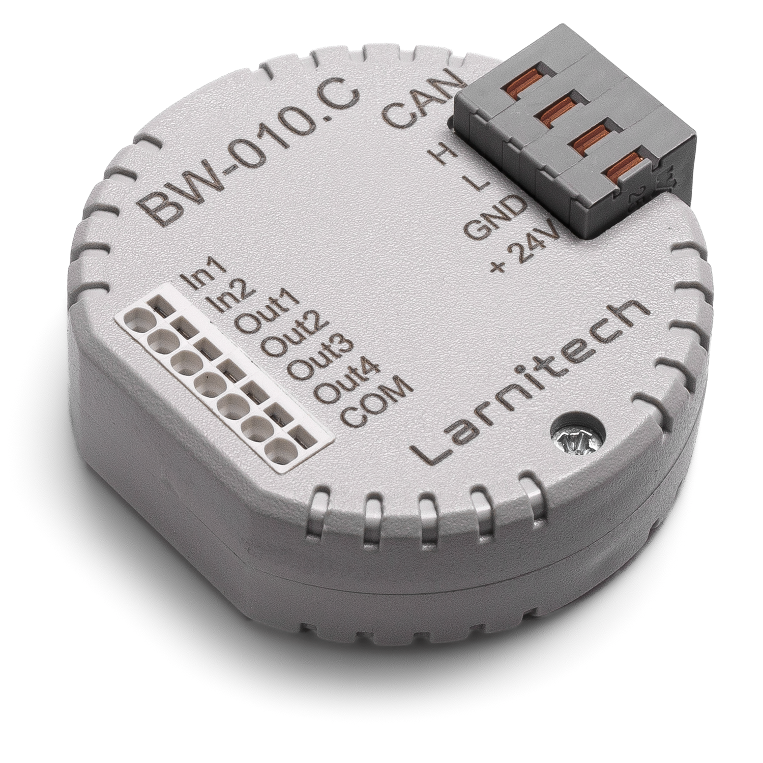
4-Х КАНАЛЬНЫЙ МОДУЛЬ ДЛЯ УСТРОЙСТВ СО ВХОДОМ 0-10 В ИЛИ ВЫХОДОМ 0-10 В
Модуль позволяет подключать устройства с входами и выходами на 0-10 В к системе Умный дом.
ВНИМАНИЕ! Все работы, связанные с установкой, подключением, настройкой, обслуживанием и поддержкой оборудования, должны выполняться только квалифицированным персоналом, обладающим достаточными навыками и опытом работы с электрооборудованием! Во избежание риска возгорания, поражения электрическим током, повреждения системы и/или травм, установка и сборка системы должны выполняться в соответствии с указаниями, перечисленными ниже:
- все работы по подключению должны выполняться при выключенном питании;
- необходимо использовать соответствующие инструменты и средства индивидуальной защиты от поражения электрическим током;
- запрещается использовать поврежденные кабели, провода и разъемы;
- избегайте перегиба проводов и кабелей;
- не прилагайте чрезмерных усилий к проводам путем их перегиба или слишком сильного сжатия: внутренние проводники кабелей и проводов могут быть оголены или повреждены;
- не используйте для подключения разъемы с плохими контактами;
- не превышайте параметры предельной нагрузки, указанные в инструкции;
- сечение питающих проводов зависит от требований к пределу плотности тока, типу изоляции и материалу проводов. Недостаточное сечение провода может привести к перегреву кабеля и возгоранию.
Когда питание включено, НИКОГДА:
- не подключайте/отключайте разъемы;
- не открывайте модули и датчики.
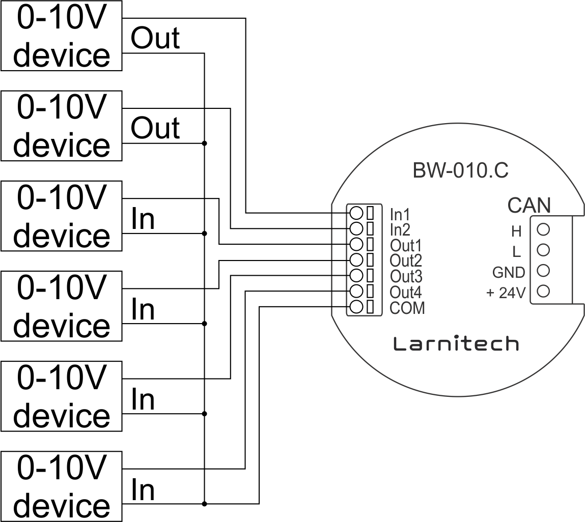
Пример подключения
Параметры модуля
| Parameter name | Value |
|---|---|
| 0-10 input port quantity | 2 |
| 0-10 output port quantity | 4 |
| Max load per channel | 15mA |
| Power supply | 11.5 … 27.5 V DC from CAN |
| Max current(24V) | 55 mA |
| Bus type | CAN (4-wire) |
| Equipment installation type | Free |
| Case material | ABS |
| Protection | IP40 |
| Temperature range | -10 … +50 °C |
| Size | 45x42x14 mm |
| Weight | 15 g |
Module installation and connection procedure
- Connect the interface connector.
- Connect the CAN connector.
- Configure the module using LT setup.
- Check all equipment for proper operation.
Module shut-off and deinstallation procedure
- Disconnect the CAN connector.
- Disconnect the interface connector.
HW settings
| Name | Type, range | SUBID | Default | Description |
|---|---|---|---|---|
| def | integer 0-250 | 1-4 | 100 | The default brightness level in case of a power reset (1..250). Example: def=250 |
| min | integer 0-100 | 1-4 | 0 | Minimum dimming level, example: min=10 |
| max | integer 0-100 | 1-4 | 100 | Maximum dimming level, example max=95 |
| start | integer 0-100 | 1-4 | 0 | The Start function is used for lamps that lack the minimal voltage to get turned on. If the set value is lower than the start value, the lamp is turned on at the start value and them the light is dimmed down to the set level. Example: start=60 |
| force | integer 0-100 | 1-4 | 10 | Time duration of the starting value (measured in milliseconds). Example: force=20 |
| runtime | integer 0-60000 | 1-4 | 1000 | Runtime is the speed of changing the brightness from 'min' to 'max' (measured in milliseconds). Example: runtime=1000 |
| dm | char[4] | 98 | 'vvvv' | Each char is responsible for the type of a particular channel
Example: dm='skl-' |
1<item addr="377:1" auto-period="600" cfgid="170" name="Dimmer 1" type="dimmer-lamp"/>
2<item addr="377:2" auto-period="600" cfgid="170" name="Dimmer 2" type="dimmer-lamp"/>
3<item addr="377:3" auto-period="600" cfgid="170" name="Dimmer 3" type="dimmer-lamp"/>
4<item addr="377:4" auto-period="600" cfgid="170" name="Dimmer 4" type="dimmer-lamp"/>
5<item addr="377:31" cfgid="170" name="Voltage" system="yes" type="voltage-sensor"/>
6<item addr="377:32" cfgid="170" name="Voltage" system="yes" type="voltage-sensor"/>
7<item addr="377:97" cfgid="170" name="Temperature" system="yes" type="temperature-sensor"/>
8<item addr="377:98" cfgid="170" logic-ver="19" name="Temperature" system="yes" type="temperature-sensor"/>