BW-DM
| BW-DM.C | |||||||||
|---|---|---|---|---|---|---|---|---|---|
 | |||||||||
| |||||||||
| |||||||||
ДИММЕР
Этот одноканальный диммер предназначен для плавного управления электрической нагрузкой (не реактивная нагрузка). Имеет 3 входных канала для подключения кнопок и герконов. Работает на МОП-транзисторах.
ВНИМАНИЕ! Все работы, связанные с установкой, подключением, настройкой, обслуживанием и поддержкой оборудования, должны выполняться только квалифицированным персоналом, обладающим достаточными навыками и опытом работы с электрооборудованием! Во избежание риска возгорания, поражения электрическим током, повреждения системы и/или травм, установка и сборка системы должны выполняться в соответствии с указаниями, перечисленными ниже:
- все работы по подключению должны выполняться при выключенном питании;
- необходимо использовать соответствующие инструменты и средства индивидуальной защиты от поражения электрическим током;
- запрещается использовать поврежденные кабели, провода и разъемы;
- избегайте перегиба проводов и кабелей;
- не прилагайте чрезмерных усилий к проводам путем их перегиба или слишком сильного сжатия: внутренние проводники кабелей и проводов могут быть оголены или повреждены;
- не используйте для подключения разъемы с плохими контактами;
- не превышайте параметры предельной нагрузки, указанные в инструкции;
- сечение питающих проводов зависит от требований к пределу плотности тока, типу изоляции и материалу проводов. Недостаточное сечение провода может привести к перегреву кабеля и возгоранию.
Когда питание включено, НИКОГДА:
- не подключайте/отключайте разъемы;
- не открывайте модули и датчики.
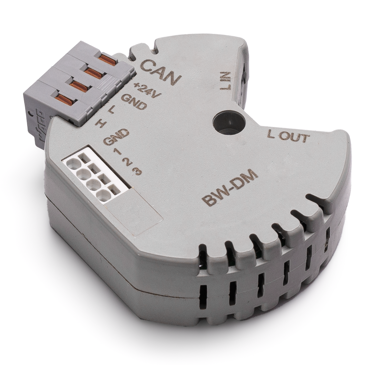
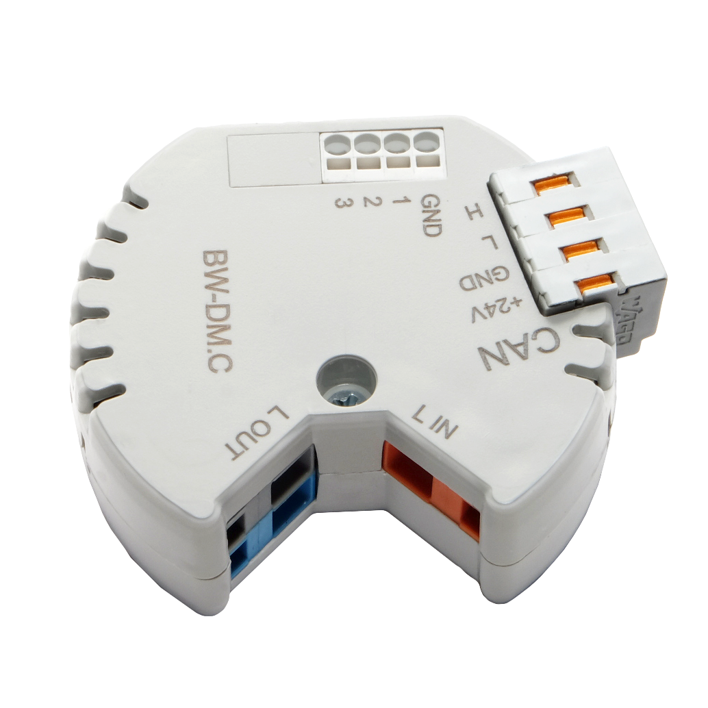
Изображение модуля
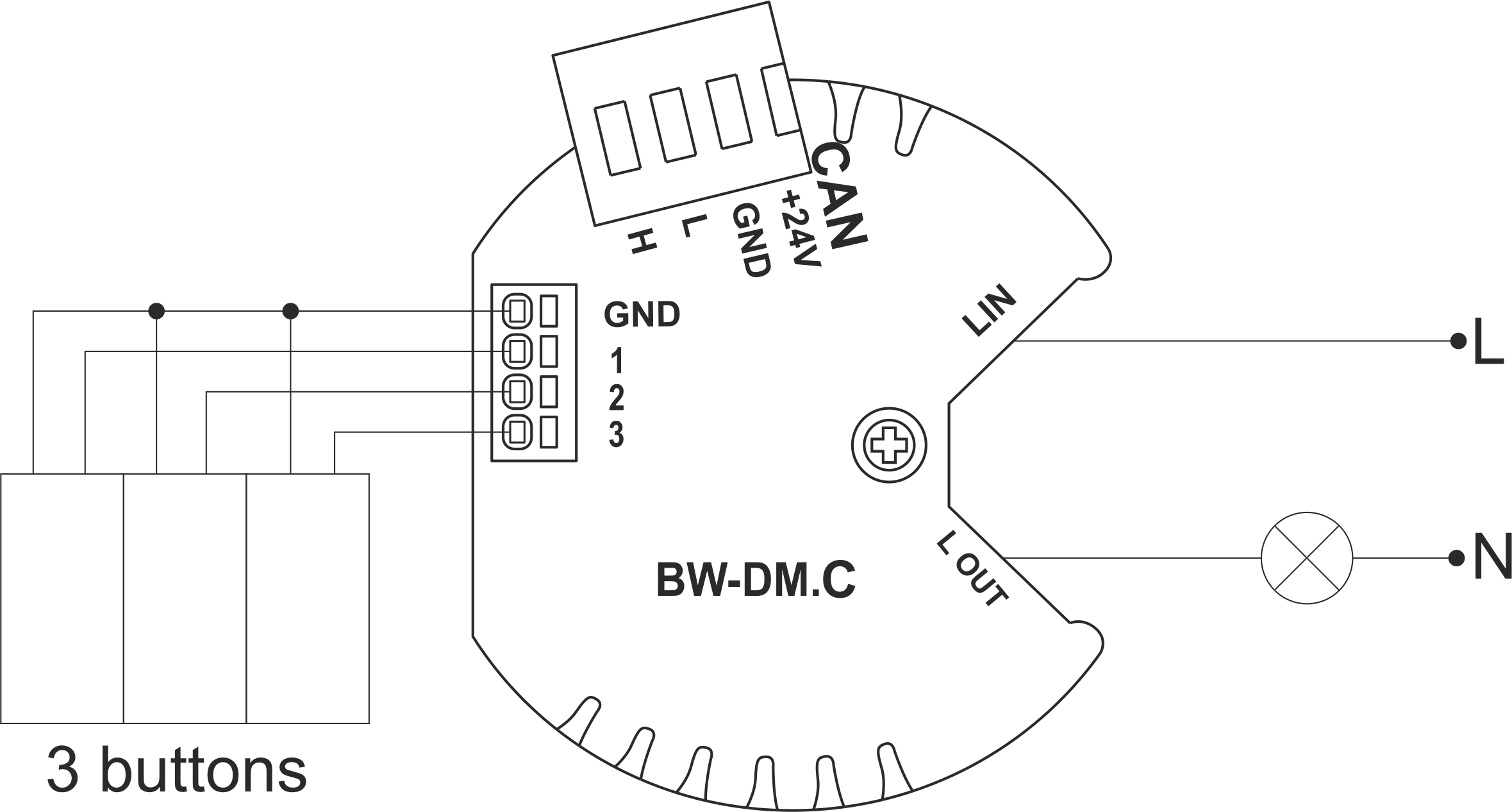
Пример подключения
Параметры модуля
| Parameter name | Value |
|---|---|
| Input channels qty | 3 |
| Output channels qty | 1 |
| Input voltage | 100-250V |
| Current type | AC |
| Max load | 0.9 A(200W at 220V) |
| Min load | 0.09 A(20W at 220V) |
| Power supply | 11.5 … 27.5 V DC from CAN |
| Max current(24V) | 40 mA |
| Temperature sensor line max length | 0.3m |
| Bus type | CAN (4-wire) |
| Equipment installation type | Free |
| Case material | ABS |
| Protection | IP40 |
| Temperature range | -10 … +50 °C |
| Size | 45x42x14 mm |
| Weight | 25 g |
Поддерживаемые типы нагрузки
| Supported load type | Power | |
|---|---|---|
 |
Conventional incandescent lamps | 20-200W |
 |
Halogen light sources | 20-200W |
 |
LED lamps with dimming support | 20-200W |
 |
Energy saving lamps with dimming support | 20-200W |
 |
Electronic ballasts with dimming support | 20-200W |
Порядок установки и подключения модуля
- Подключите выходы.
- Подключите входы.
- Подсоедините разъем шины CAN.
- Настройте модуль с помощью LT SETUP.
- Подайте питание на нагружаемые элементы системы.
- Проверьте все оборудование на правильность работы.
Отключение модуля и процедура демонтажа
- Disconnect the power from the load.
- Disconnect the CAN connector.
- Disconnect the inputs.
- Disconnect the outputs.
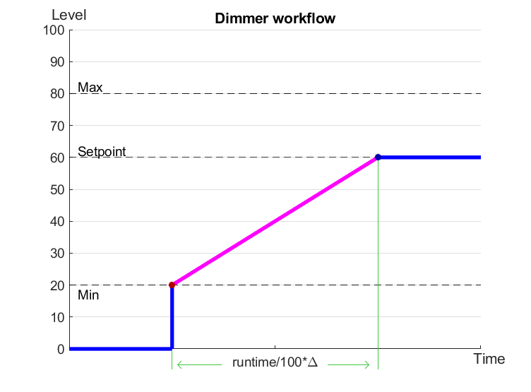
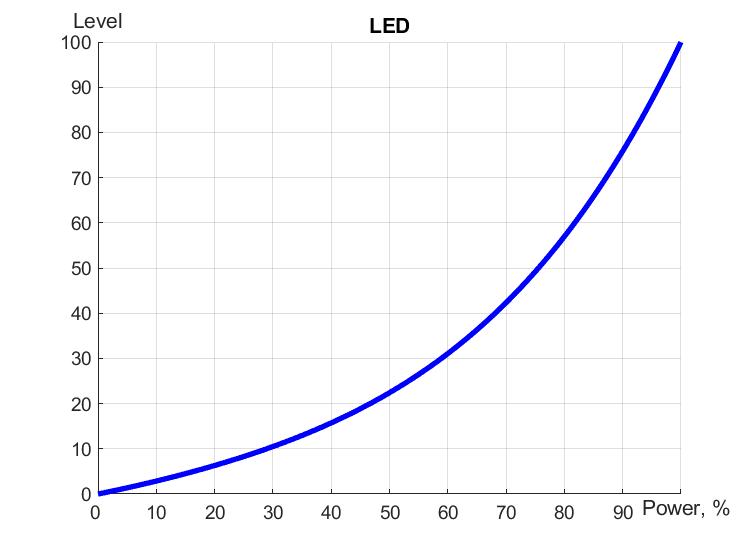
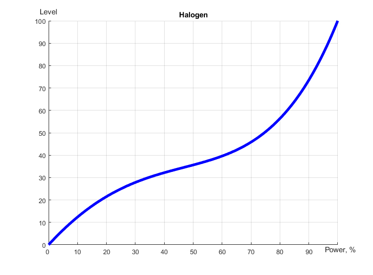
Dimmer workflow
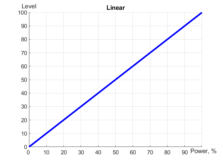
Linear, LED and Halogen workflows
HW settings
| Name | Type, range | SUBID | Default | Description |
|---|---|---|---|---|
| def | integer 0-250 | 1 | 100 | The default brightness level in case of a power reset (1..250). Example: def=250 |
| min | integer 0-100 | 1 | 0 | Minimum dimming level, example: min=10 |
| max | integer 0-100 | 1 | 100 | Maximum dimming level, example max=95 |
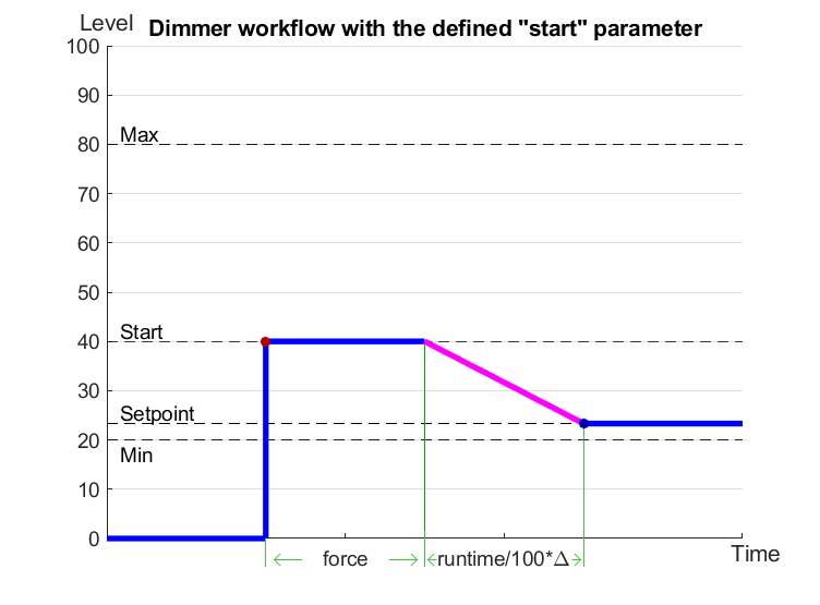
| start | integer 0-100 | 1 | 0 | The Start function is used for lamps that lack the minimal voltage to get turned on. If the set value is lower than the start value, the lamp is turned on at the start value and them the light is dimmed down to the set level. Example: start=60 |
| force | integer 0-100 | 1 | 10 | Time duration of the starting value (measured in milliseconds). Example: force=20 |
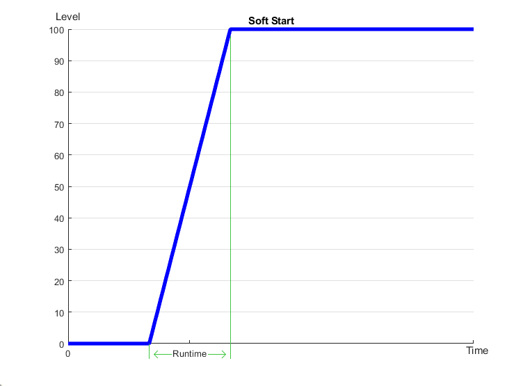
| runtime | integer 0-60000 | 1 | 1000 | Runtime is the speed of changing the brightness from ‘min’ to ‘max’ (measured in milliseconds). Example: runtime=1000 |
| protect | integer 0;1 | 1 | 0 | Overload Protect. 0(off); 1 (on), example: protect=0 |
| offset | float(+/- 0…39) | 30 | 0 | sensor values offset;
For example, offset is -3.8 : 1hw="offset='-3.8'"
|
| mode | string | 98 | disabled | Frequency of pulse-width modulation in Hz for item with direct current.
Example: mode='dc400' |
| dm | char | 98 | 'g' | Each char is responsible for the type of a particular channel
Example: dm='s' |
| in | char[3] | 98 | 'BBB' | Each char is responsible for the type of a particular channel
And you can also connect one temperature sensor: 1hw="in='T+-'"
Example: in='BCB' |
Input HW configuration
| chanel | 1 | 2 | 3 | 4 | 5 | 6 |
|---|---|---|---|---|---|---|
| Button nButton Switch Contact nContact none |
+ | + | + | + | + | + |
| LedButton nLedButton |
+ | + | + | + | + | |
| Temperature Sensor | + |
1<item addr="491:1" auto-period="600" cfgid="72" name="Dimmer" hw="def=200 min=30 max=88 start=35 force=20 runtime=1000" type="dimer-lamp" uniq_id="4610"/>
2<item addr="491:11" cfgid="72" name="Switch" type="switch" uniq_id="4611"/>
3<item addr="491:12" cfgid="72" name="Switch" type="switch" uniq_id="4612"/>
4<item addr="491:13" cfgid="72" name="Door" type="door-sensor" uniq_id="4616"/>
5<item addr="491:97" cfgid="72" name="Temperature" system="yes" type="temperature-sensor" uniq_id="4614"/>
6<item addr="491:98" cfgid="72" hw="dm='G' in='BSH'" name="Temperature" system="yes" type="temperature-sensor" uniq_id="4615"/>