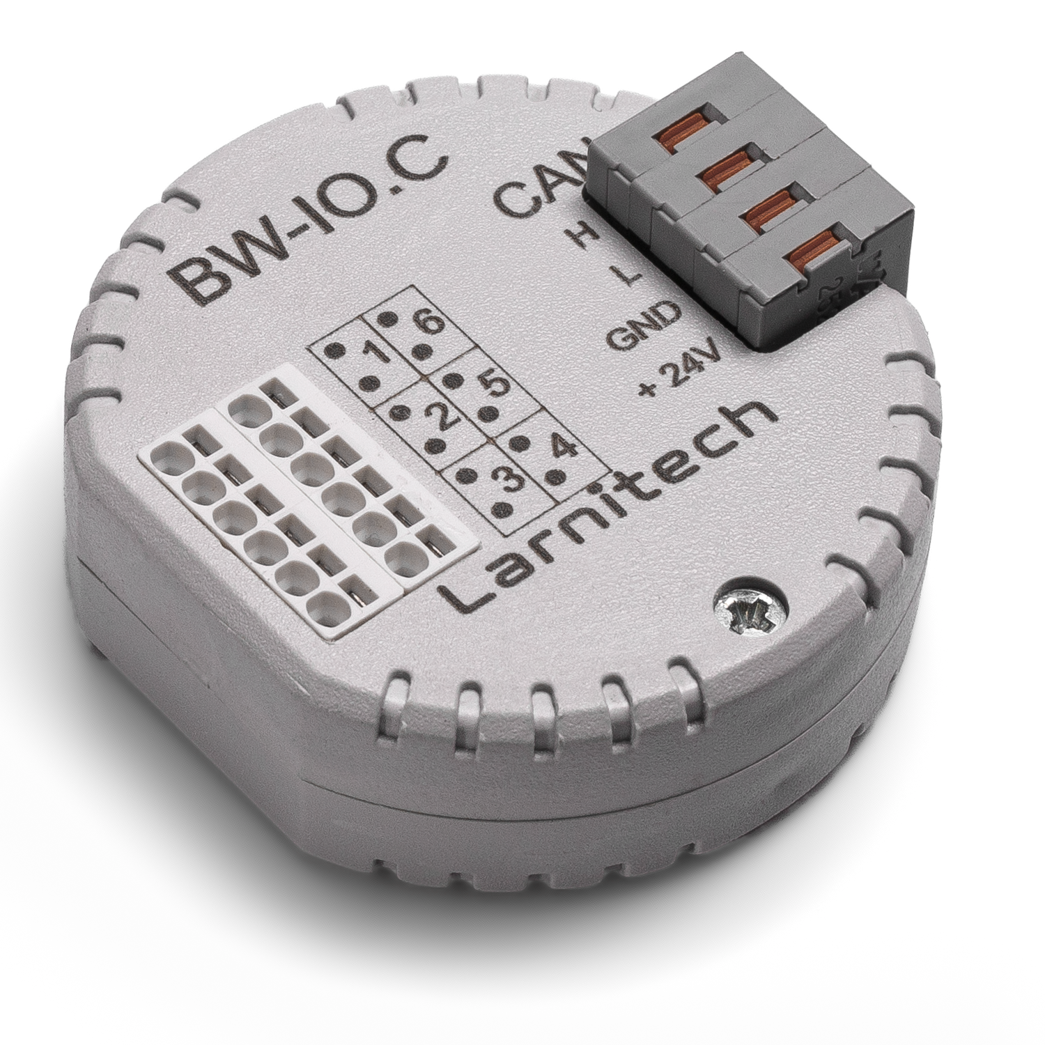
BW-IO
From Larnitech wiki page
Jump to navigation
Jump to search
| BW-IO.C |
|---|
 |
|
| Number of switched channels | 3 |
|---|
|
|
|
| Supply voltage | 11.5...27.5 V DC |
|---|
| Dimentions | 45x42x14 mm |
|---|
|
6-CHANNEL I/O MODULE
The module is designed for connection of other digital devices which
do not have standard interfaces
CAUTION! All work related to the installation, connection, setting up, service and support must be carried out by qualified personnel with sufficient skills and experience in working with electrical equipment.
To avoid the risk of fire, electric shock, damage to the system and/or personal injury, the system installation and assembly must be performed in accordance with the instructions listed below:
- all connectivity work must be carried out with the power turned OFF;
- use appropriate tools and personal protection against electric shock;
- do not use damaged cables, wires and connectors;
- avoid folding the cables and wires;
- do not apply excessive force to the wires by kinking or pressing them too hard: the inner conductors of the cables and wires may get stripped or damaged;
- do not use the power socket with poor contacts to connect;
- do not exceed the load limit parameters specified in the manual;
- the supply conductors wire section is subject to the specifications for current density limit, insulation type and wire material. Light section can result in cable overheating and fire.
When the power is on, NEVER:
- connect/disconnect the connectors;
- open modules and sensors.
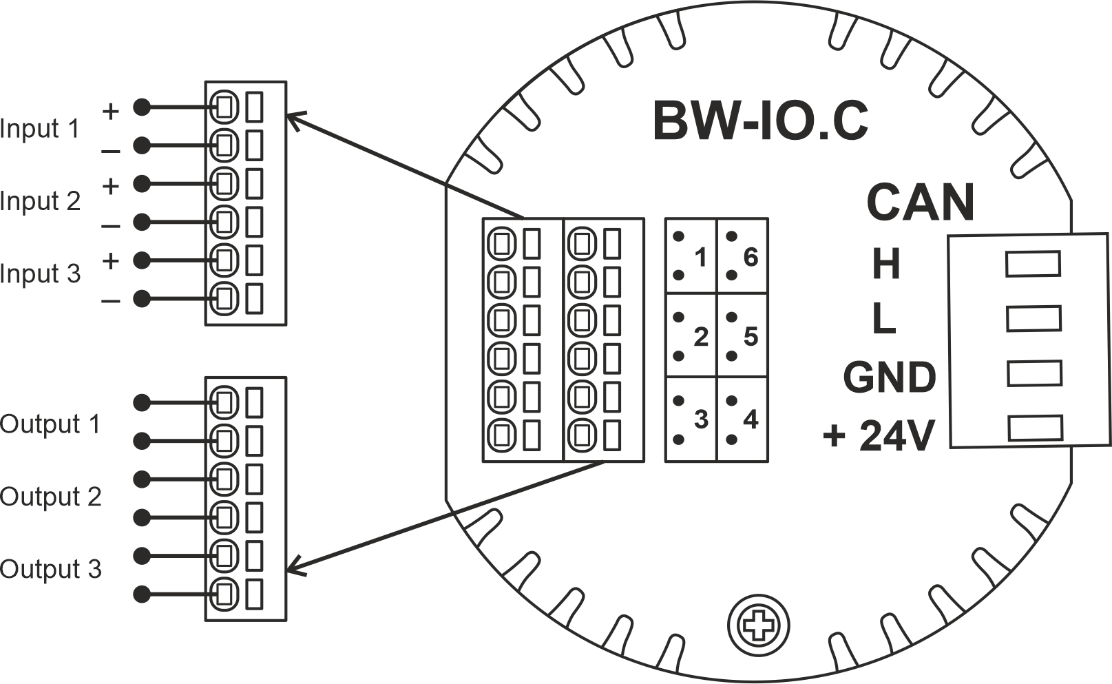
Example of connection
Module parameters
| Parameter name |
Value
|
| Input channels qty |
3
|
| Input/output channels qty |
|
| 0-10 input port quantity |
|
| Buttons |
|
| LED Buttons |
|
| Number of sensor inputs |
|
| Number of dry contact inputs |
|
| RS485 ports qty |
|
| RS232 ports qty |
|
| UART ports qty |
|
| M-BUS port quantity |
|
| Pulse inputs quantity |
|
| DALI ports qty |
|
| DALI-line voltage supply |
|
| Peak current of DALI-line power supply |
|
| Peak current in DALI-line |
|
| Maximum DALI devices quantity |
|
| Dimming channels qty |
|
| Output channels qty |
3
|
| 0-10 output port quantity |
|
| Analog output channels qty |
|
| Output |
|
| Digital line maximum length |
|
| Discrete input channels qty |
|
| Digital input channels qty |
|
| Speakers |
|
| Max power output audio channel |
|
| Camera |
|
| IR lighting |
|
| Card reader |
|
| Connection type |
|
| Protocols |
|
| Backlight voltage |
|
| Load type |
|
| Dimmer load type |
|
| Supported sensors |
|
| Input voltage |
|
| Current type |
|
| Adjustment type |
|
| Max load |
|
| Min load |
|
| Max load per channel |
|
| Max load per group |
|
| Max load per device |
|
| Control parameters |
|
| Angle of vision IR |
°
|
| Angle of motion |
°
|
| Temperature measuring range |
°C
|
| Humidity measuring range |
|
| Dimmer type |
|
| Dimming type |
|
| Voltage that may be applied to the input channels |
|
| Max output switching voltage |
60V AC/DC
|
| Max output switching current |
50mA
|
| Power supply |
11.5 … 27.5 V DC from CAN
|
| Max current(24V) |
25 mA
|
| Max current(13V) |
|
| Max detection distance |
|
| Max IR distance |
|
| Max BT distance |
|
| Max current |
|
| Relay |
|
| Data transfer speed |
|
| Permissible section of power supply cable to connect in socket: |
|
| Sensors VCC output |
|
| Sensors max VCC current |
|
| R1-R2 inputs max current |
|
| Push-button/reed switches line recommended length |
|
| Temperature sensor line max length |
|
| Sensor cable length |
|
| Sensors line max length |
|
| Bus type |
CAN (4-wire)
|
| Compatible with |
|
| Output voltage |
|
| Output current |
|
| Equipment installation type |
Free
|
| Mounting |
|
| Max cabel lenght |
|
| Case material |
ABS
|
| Protection |
IP40
|
| Temperature range |
-10 … +50 °C
|
| Size |
45x42x14 mm
|
| Weight |
15 g
|
* -
** -
*** -
1 -
2 -
3 -
Module installation and connection procedure
- Connect the outputs.
- Connect the inputs.
- Connect the CAN connector.
- Configure the module using LT setup.
- Check all equipment for proper operation.
Module shut-off and deinstallation procedure
- Disconnect the CAN connector.
- Disconnect the inputs.
- Disconnect the outputs.
HW settings
| Name |
Type, range |
SUBID |
Default |
Description
|
| io |
char[6] |
98 |
'HHHLLL' |
Each char is responsible for the type of a particular channel
- 1-3 channels
- 'H' – Contact
- 'K' – Inverted contact
- 'L' – Backlit button
- 'M' – Inverted backlit button
- 4-6 channels
- 'L'-Lamp
- 'M'-Lamp Inverse;
- 'J'-Heating NO, valve-heating, normally open;
- 'H'-Heating NC, valve-heating, normally closed;
- 'B'-Blinds, jalousie/curtains(2 pole);
- 'C'-Blinds Inverse, jalousie/curtains, invert open-close(2 pole);
- 'G'-Gate (2 pole), 2 pole gate;
- 'D'-Gate (2 pole) Inverse, 2 pole gate, invert open-close;
- 'X'-Gate (1 pole /short press), 1 pole gate;
- 'Z'-Gate (1 pole) Inverse, 1 pole gate, invert open-close;
- 'V'-Valve (2 pole), 2 pole valve,;
- 'W'-Valve (2 pole) Inverse, 2 pole valve, invert open-close;
- 'R'-Valve (1 pole), 1 pole valve;
- 'S'-Valve (1 pole) Inverse, 1 pole valve, invert open-close;
- 'K'-Lock (short press);
- 'N'-Lock (short press) Inverse;
- 'F'-FanCoil. Group1 (Lamp Toggle). For fancoil speed control;
- 'E'-FanCoil. Group2 (Lamp Toggle). For fancoil speed control;
- 'Q'-FanCoil. Group3 (Lamp Toggle). For fancoil speed control;
- 'U'-FanCoil. Group4 (Lamp Toggle). For fancoil speed control;
- 'I'-FanCoil. Group5 (Lamp Toggle). For fancoil speed control;
- '-'-none, nothing is connected.
Example:
|