Difference between revisions of "BW-IO/ru"
Jump to navigation
Jump to search
(Created page with "#Подключите выходы. #Подключите входы. #Подсоедините разъем шины CAN. #Настройте модуль с помощью L...") |
(Created page with "==Отключение модуля и процедура демонтажа==") |
||
| Line 61: | Line 61: | ||
#Проверьте все оборудование на правильность работы. | #Проверьте все оборудование на правильность работы. | ||
| − | == | + | ==Отключение модуля и процедура демонтажа== |
#Disconnect the CAN connector. | #Disconnect the CAN connector. | ||
Revision as of 13:48, 9 January 2022
| BW-IO.C | |||||||
|---|---|---|---|---|---|---|---|
 | |||||||
| |||||||
| |||||||
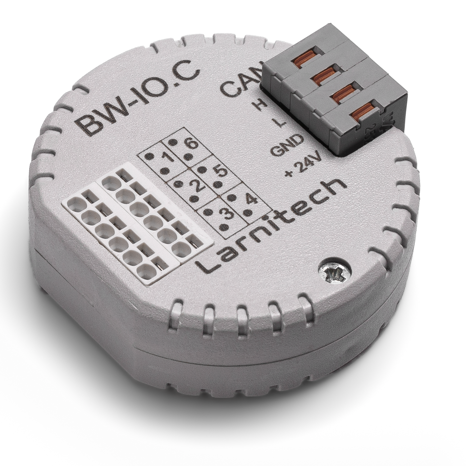
6-ТИ КАНАЛЬНЫЙ МОДУЛЬ ВХОДОВ/ВЫХОДОВ
Модуль предназначен для подключения сторонних цифровых устройств, которые не имеют стандартных интерфейсов
ВНИМАНИЕ! Все работы, связанные с установкой, подключением, настройкой, обслуживанием и поддержкой оборудования, должны выполняться только квалифицированным персоналом, обладающим достаточными навыками и опытом работы с электрооборудованием! Во избежание риска возгорания, поражения электрическим током, повреждения системы и/или травм, установка и сборка системы должны выполняться в соответствии с указаниями, перечисленными ниже:
- все работы по подключению должны выполняться при выключенном питании;
- необходимо использовать соответствующие инструменты и средства индивидуальной защиты от поражения электрическим током;
- запрещается использовать поврежденные кабели, провода и разъемы;
- избегайте перегиба проводов и кабелей;
- не прилагайте чрезмерных усилий к проводам путем их перегиба или слишком сильного сжатия: внутренние проводники кабелей и проводов могут быть оголены или повреждены;
- не используйте для подключения разъемы с плохими контактами;
- не превышайте параметры предельной нагрузки, указанные в инструкции;
- сечение питающих проводов зависит от требований к пределу плотности тока, типу изоляции и материалу проводов. Недостаточное сечение провода может привести к перегреву кабеля и возгоранию.
Когда питание включено, НИКОГДА:
- не подключайте/отключайте разъемы;
- не открывайте модули и датчики.
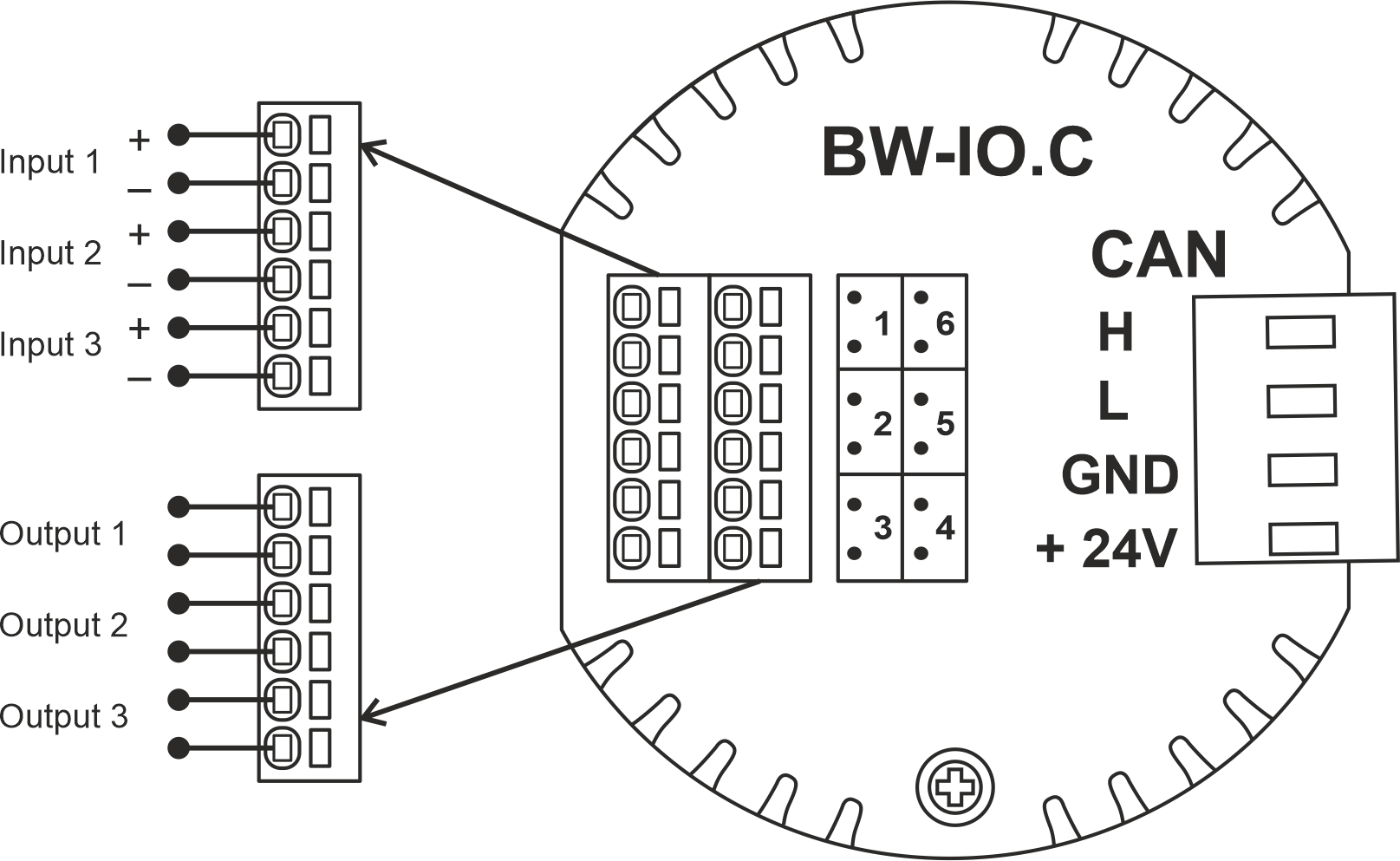
Пример подключения
Параметры модуля
| Parameter name | Value |
|---|---|
| Input channels qty | 3 |
| Output channels qty | 3 |
| Voltage that may be applied to the input channels | |
| Max output switching voltage | 60V AC/DC |
| Max output switching current | 50mA |
| Power supply | 11.5 … 27.5 V DC from CAN |
| Max current(24V) | 25 mA |
| Bus type | CAN (4-wire) |
| Equipment installation type | Free |
| Case material | ABS |
| Protection | IP40 |
| Temperature range | -10 … +50 °C |
| Size | 45x42x14 mm |
| Weight | 15 g |
Порядок установки и подключения модуля
- Подключите выходы.
- Подключите входы.
- Подсоедините разъем шины CAN.
- Настройте модуль с помощью LT SETUP.
- Проверьте все оборудование на правильность работы.
Отключение модуля и процедура демонтажа
- Disconnect the CAN connector.
- Disconnect the inputs.
- Disconnect the outputs.
HW settings
| Name | Type, range | SUBID | Default | Description |
|---|---|---|---|---|
| io | char[6] | 98 | 'HHHLLL' | Each char is responsible for the type of a particular channel
Example: 1hw="io='KKKLLL'"
|