Difference between revisions of "BW-LC02/ru"
(Created page with "<div class="caution"> ВНИМАНИЕ! Все работы, связанные с установкой, подключением, настройкой, обслуживан...") |
(Created page with "==Пример подключения==") |
||
| Line 50: | Line 50: | ||
</div> | </div> | ||
| − | == | + | ==Пример подключения== |
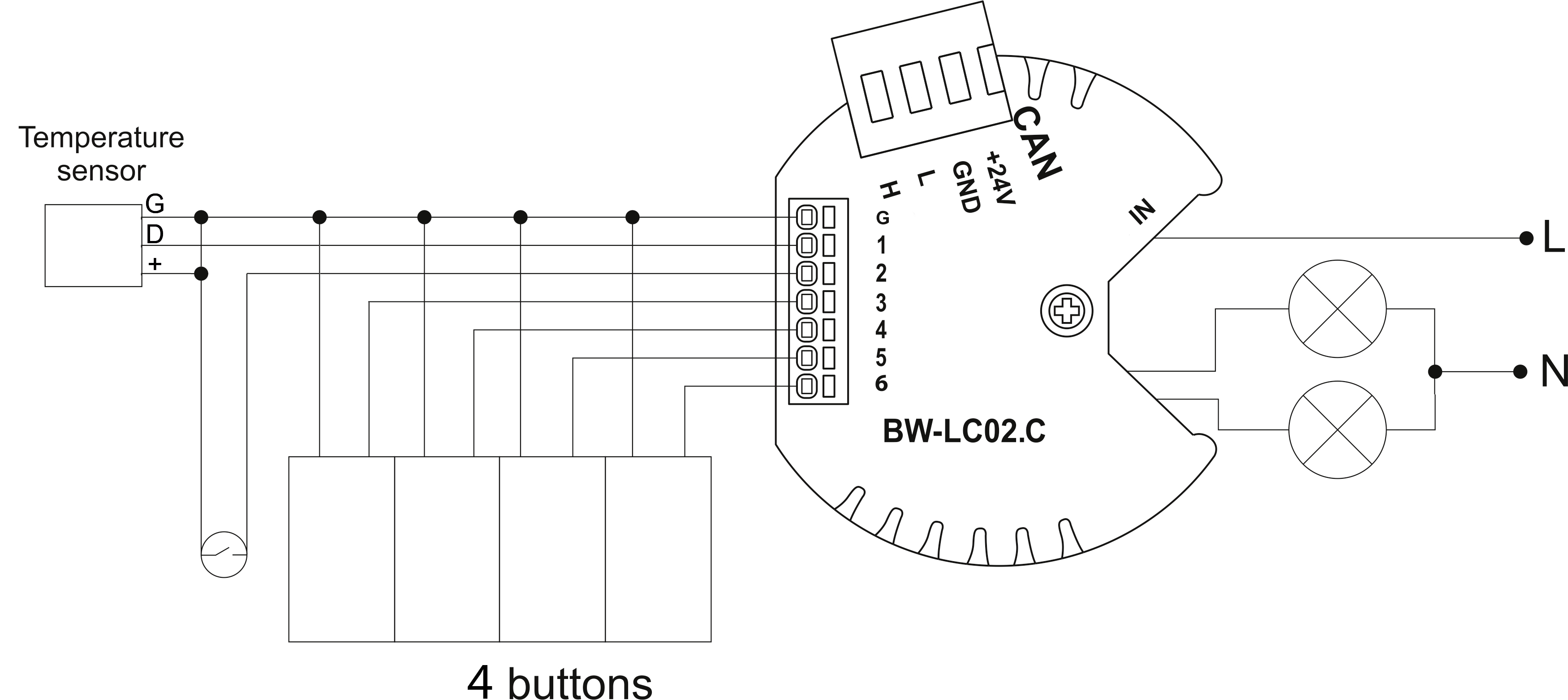
[[File:LC02C EXA.png|700px]] | [[File:LC02C EXA.png|700px]] | ||
Revision as of 13:44, 8 January 2022
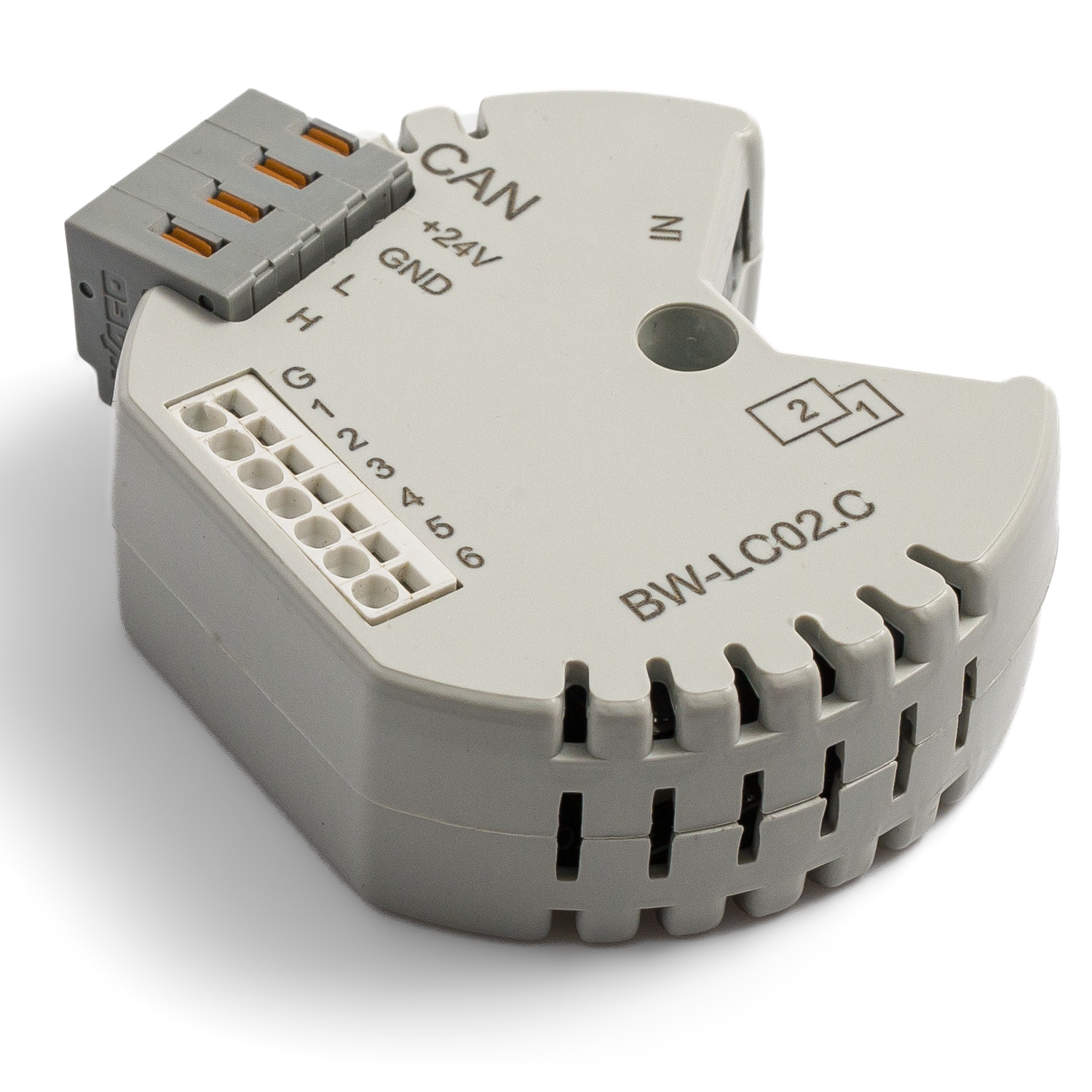
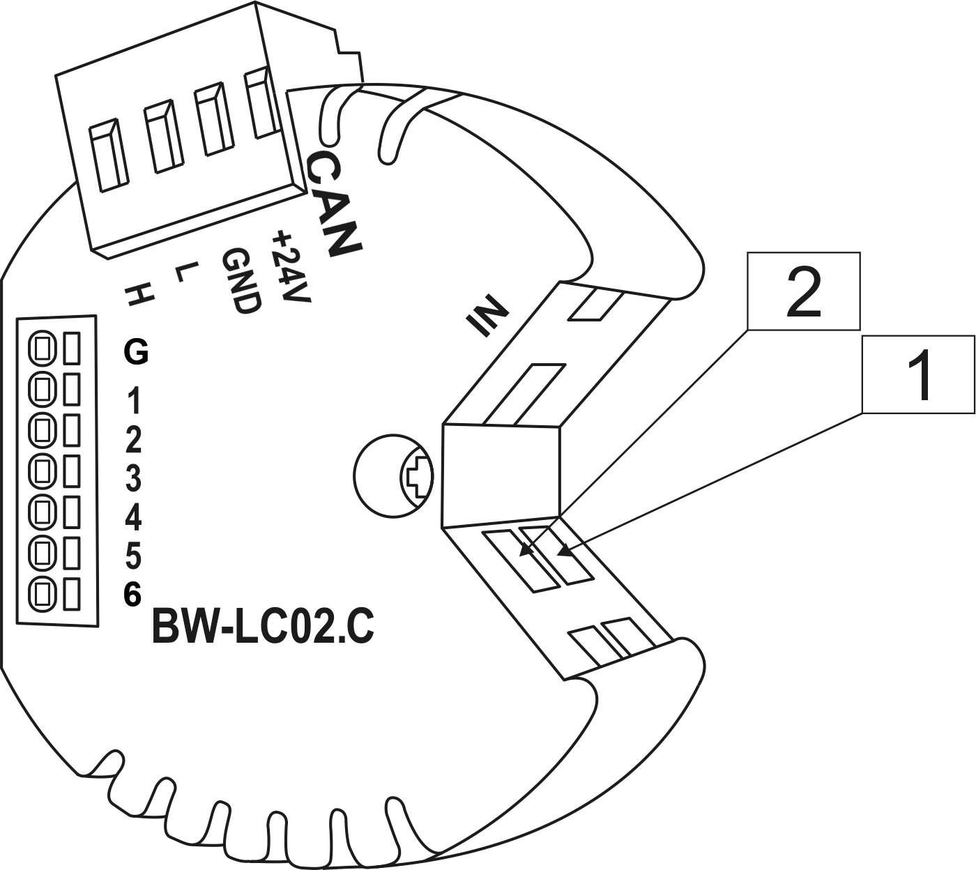
| BW-LC02.C | |||||||||
|---|---|---|---|---|---|---|---|---|---|
 | |||||||||
| |||||||||
| |||||||||
2-Х КАНАЛЬНОЕ РЕЛЕ
Модуль предназначен для коммутации цепей постоянного и переменного тока. Применяется для управления освещением и другими электрическими устройствами. Имеет 6 входов для подключения кнопок и герконов.
Функции
- Компактные размеры (толщина - всего 16 мм)
- 6 входов поддерживают:
- Кнопки
- Выключатели
- Герконы
- Светодиодные кнопки
- Цифровые датчики температуры
- Выходы поддерживают:
- Освещение
- Клапаны отопления NC/NO
- Замки NC/NO
- Жалюзи
- Шторы
- Экраны проектора
- Клапаны
ВНИМАНИЕ! Все работы, связанные с установкой, подключением, настройкой, обслуживанием и поддержкой оборудования, должны выполняться только квалифицированным персоналом, обладающим достаточными навыками и опытом работы с электрооборудованием! Во избежание риска возгорания, поражения электрическим током, повреждения системы и/или травм, установка и сборка системы должны выполняться в соответствии с указаниями, перечисленными ниже:
- все работы по подключению должны выполняться при выключенном питании;
- необходимо использовать соответствующие инструменты и средства индивидуальной защиты от поражения электрическим током;
- запрещается использовать поврежденные кабели, провода и разъемы;
- избегайте перегиба проводов и кабелей;
- не прилагайте чрезмерных усилий к проводам путем их перегиба или слишком сильного сжатия: внутренние проводники кабелей и проводов могут быть оголены или повреждены;
- не используйте для подключения разъемы с плохими контактами;
- не превышайте параметры предельной нагрузки, указанные в инструкции;
- сечение питающих проводов зависит от требований к пределу плотности тока, типу изоляции и материалу проводов. Недостаточное сечение провода может привести к перегреву кабеля и возгоранию.
Когда питание включено, НИКОГДА:
- не подключайте/отключайте разъемы;
- не открывайте модули и датчики.
Пример подключения
Module parameters
| Parameter name | Value |
|---|---|
| Input channels qty | 6 |
| Buttons | 6 |
| LED Buttons | 5 |
| Output channels qty | 2 |
| Backlight voltage | 3V |
| Input voltage | 0-250V |
| Current type | AC/DC |
| Max load per channel | 2A |
| Power supply | 11.5 … 27.5 V DC from CAN |
| Max current(24V) | 35 mA |
| Permissible section of power supply cable to connect in socket: single-conductor cable multiple-conductor cable tipped multiple-conductor cable |
0.5 … 4mm2 0.5 … 4mm2 0.5 … 2.5mm2 |
| Temperature sensor line max length | 10m |
| Bus type | CAN (4-wire) |
| Equipment installation type | Free |
| Case material | ABS |
| Protection | IP40 |
| Temperature range | -10 … +50 °C |
| Size | 45x42x14 mm |
| Weight | 25 g |
Module installation and connection procedure
- Connect the outputs.
- Connect the inputs.
- Connect the CAN connector.
- Configure the module using LT setup.
- Apply power to the load.
- Check all equipment for proper operation.
Module shut-off and deinstallation procedure
- Disconnect the power from the load.
- Disconnect the CAN connector.
- Disconnect the inputs.
- Disconnect the outputs.
HW settings
| Name | Type, range | SUBID | Default | Description |
|---|---|---|---|---|
| runtime | integer 0-100 | 1-2 | 15 | runtime is the open/close time in seconds, is used for jalousie, gate, valve(2 pole); Example: runtime=15 |
| hold | integer 0-10000 | 1-2 | 500 | hold is the bridging time in miliseconds, is used for gate and jalousie (by default hold is the same as runtime), lock; Example: hold=3500 |
| def | string 'ON' | 1-2 | 'OFF' | Def is the element status is set after restart, is used for lamp, heating, valve(1 pole); Example: def='ON' |
| offset | float(+/- 0…39) | 30 | '0' | sensor values offset;
For example, offset is -3.8 : 1hw="offset='-3.8'"
|
| stop | Char 'R' | 1 | – | (for 2-pole gate and blinds) If it is declared then by Stop command during the motion, the same impulse appears as it was at the beginning of the motion. Pole, an which the stop-impules is formed, is defined by the parameter Stop value. If it is 'r' or 'R' then stop-impulse is produced on the opposite to the start-impulse pole. If any other value is delcared (e.g., 'd' ) then the stop-impulse is on the same pole. If a Runtime passed after the beginning of the motion then the stop-impulse is not formed. Example: stop='r' |
| out | char[2] | 98 | 'LL' | Each char is responsible for the type of a particular channel
Example: 1hw="out='LM'"
|
| in | char[6] | 98 | 'BBBBKK' | Each char is responsible for the type of a particular channel
and you can also connect one temperature sensor 1in='T-----'
Example: 1hw="in='BBBKKK'"
|
Input HW configuration
| chanel | 1 | 2 | 3 | 4 | 5 | 6 |
|---|---|---|---|---|---|---|
| Button nButton Switch Contact nContact none |
+ | + | + | + | + | + |
| LedButton nLedButton |
+ | + | + | + | + | |
| Temperature Sensor | + |
1<item addr="501:1" cfgid="171" name="Valve" type="valve" uniq_id="4169"/>
2<item addr="501:14" cfgid="171" name="Door" type="door-sensor" uniq_id="4168"/>
3<item addr="501:15" cfgid="171" name="Switch" type="switch" uniq_id="4128"/>
4<item addr="501:30" cfgid="171" name="Temperature" hw="offset='-10'" type="temperature-sensor" uniq_id="4171"/>
5<item addr="501:97" cfgid="171" name="Temperature" system="yes" type="temperature-sensor" uniq_id="3998"/>
6<item addr="501:98" cfgid="171" hw="out='V-' in='T--KD-'" name="Temperature" system="yes" type="temperature-sensor" uniq_id="3999"/>