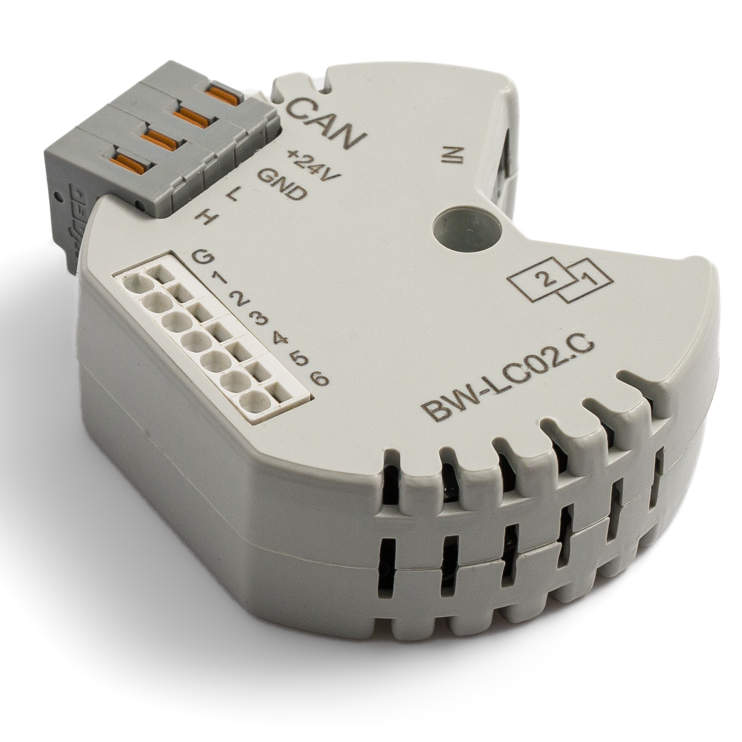
BW-LC02
Jump to navigation
Jump to search
| BW-LC02.C | |||||||||
|---|---|---|---|---|---|---|---|---|---|
 | |||||||||
| |||||||||
| |||||||||
2-Х КАНАЛЬНОЕ РЕЛЕ
Модуль предназначен для коммутации цепей постоянного и переменного тока. Применяется для управления освещением и другими электрическими устройствами. Имеет 6 входов для подключения кнопок и герконов.
Features
- Compact size (only 16mm thickness)
- 6 inputs support:
- Buttons
- Switches
- reed switches
- LED buttons
- digital temperature sensor
- Outputs support:
- Lights
- NC/NO heating valves
- NC/NO locks
- Blinds
- Сurtains
- Projector screens
- Valves
CAUTION! All work related to the installation, connection, setting up, service and support must be carried out by qualified personnel with sufficient skills and experience in working with electrical equipment. To avoid the risk of fire, electric shock, damage to the system and/or personal injury, the system installation and assembly must be performed in accordance with the instructions listed below:
- all connectivity work must be carried out with the power turned OFF;
- use appropriate tools and personal protection against electric shock;
- do not use damaged cables, wires and connectors;
- avoid folding the cables and wires;
- do not apply excessive force to the wires by kinking or pressing them too hard: the inner conductors of the cables and wires may get stripped or damaged;
- do not use the power socket with poor contacts to connect;
- do not exceed the load limit parameters specified in the manual;
- the supply conductors wire section is subject to the specifications for current density limit, insulation type and wire material. Light section can result in cable overheating and fire.
When the power is on, NEVER:
- connect/disconnect the connectors;
- open modules and sensors.
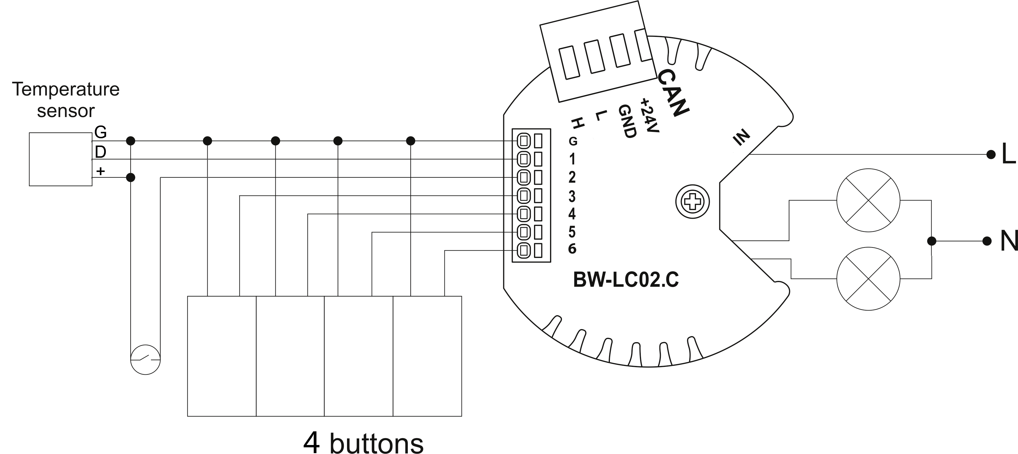
Example of connection
Module parameters
| Parameter name | Value |
|---|---|
| Input channels qty | 6 |
| Buttons | 6 |
| LED Buttons | 5 |
| Output channels qty | 2 |
| Backlight voltage | 3V |
| Input voltage | 0-250V |
| Current type | AC/DC |
| Max load per channel | 2A |
| Power supply | 11.5 … 27.5 V DC from CAN |
| Max current(24V) | 35 mA |
| Permissible section of power supply cable to connect in socket: single-conductor cable multiple-conductor cable tipped multiple-conductor cable |
0.5 … 4mm2 0.5 … 4mm2 0.5 … 2.5mm2 |
| Temperature sensor line max length | 10m |
| Bus type | CAN (4-wire) |
| Equipment installation type | Free |
| Case material | ABS |
| Protection | IP40 |
| Temperature range | -10 … +50 °C |
| Size | 45x42x14 mm |
| Weight | 25 g |
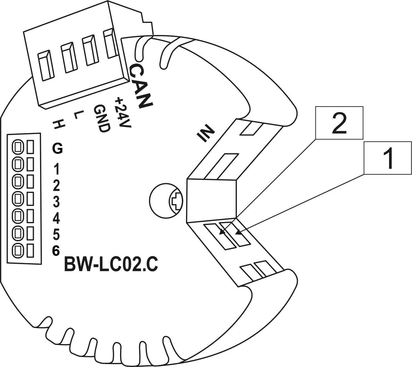
Module installation and connection procedure
- Connect the outputs.
- Connect the inputs.
- Connect the CAN connector.
- Configure the module using LT setup.
- Apply power to the load.
- Check all equipment for proper operation.
Module shut-off and deinstallation procedure
- Disconnect the power from the load.
- Disconnect the CAN connector.
- Disconnect the inputs.
- Disconnect the outputs.
HW settings
| Name | Type, range | SUBID | Default | Description |
|---|---|---|---|---|
| runtime | integer 0-100 | 1-2 | 15 | runtime is the open/close time in seconds, is used for jalousie, gate, valve(2 pole); Example: runtime=15 |
| hold | integer 0-10000 | 1-2 | 500 | hold is the bridging time in miliseconds, is used for gate and jalousie (by default hold is the same as runtime), lock; Example: hold=3500 |
| def | string 'ON' | 1-2 | 'OFF' | Def is the element status is set after restart, is used for lamp, heating, valve(1 pole); Example: def='ON' |
| offset | float(+/- 0…39) | 30 | '0' | sensor values offset;
For example, offset is -3.8 : 1hw="offset='-3.8'"
|
| stop | Char 'R' | 1 | – | (for 2-pole gate and blinds) If it is declared then by Stop command during the motion, the same impulse appears as it was at the beginning of the motion. Pole, an which the stop-impules is formed, is defined by the parameter Stop value. If it is 'r' or 'R' then stop-impulse is produced on the opposite to the start-impulse pole. If any other value is delcared (e.g., 'd' ) then the stop-impulse is on the same pole. If a Runtime passed after the beginning of the motion then the stop-impulse is not formed. Example: stop='r' |
| out | char[2] | 98 | 'LL' | Each char is responsible for the type of a particular channel
Example: 1hw="out='LM'"
|
| in | char[6] | 98 | 'BBBBKK' | Each char is responsible for the type of a particular channel
and you can also connect one temperature sensor 1in='T-----'
Example: 1hw="in='BBBKKK'"
|
Input HW configuration
| chanel | 1 | 2 | 3 | 4 | 5 | 6 |
|---|---|---|---|---|---|---|
| Button nButton Switch Contact nContact none |
+ | + | + | + | + | + |
| LedButton nLedButton |
+ | + | + | + | + | |
| Temperature Sensor | + |
1<item addr="501:1" cfgid="171" name="Valve" type="valve" uniq_id="4169"/>
2<item addr="501:14" cfgid="171" name="Door" type="door-sensor" uniq_id="4168"/>
3<item addr="501:15" cfgid="171" name="Switch" type="switch" uniq_id="4128"/>
4<item addr="501:30" cfgid="171" name="Temperature" hw="offset='-10'" type="temperature-sensor" uniq_id="4171"/>
5<item addr="501:97" cfgid="171" name="Temperature" system="yes" type="temperature-sensor" uniq_id="3998"/>
6<item addr="501:98" cfgid="171" hw="out='V-' in='T--KD-'" name="Temperature" system="yes" type="temperature-sensor" uniq_id="3999"/>