BW-RGB
Jump to navigation
Jump to search
| BW-RGB.C | |||||||
|---|---|---|---|---|---|---|---|
 | |||||||
| |||||||
3-Х КАНАЛЬНЫЙ КОНТРОЛЛЕР СВЕТОДИОДНОГО ОСВЕЩЕНИЯ
Модуль обеспечивает управление одной цветной или тремя монохромными светодиодными лентами.
ВНИМАНИЕ! Все работы, связанные с установкой, подключением, настройкой, обслуживанием и поддержкой оборудования, должны выполняться только квалифицированным персоналом, обладающим достаточными навыками и опытом работы с электрооборудованием! Во избежание риска возгорания, поражения электрическим током, повреждения системы и/или травм, установка и сборка системы должны выполняться в соответствии с указаниями, перечисленными ниже:
- все работы по подключению должны выполняться при выключенном питании;
- необходимо использовать соответствующие инструменты и средства индивидуальной защиты от поражения электрическим током;
- запрещается использовать поврежденные кабели, провода и разъемы;
- избегайте перегиба проводов и кабелей;
- не прилагайте чрезмерных усилий к проводам путем их перегиба или слишком сильного сжатия: внутренние проводники кабелей и проводов могут быть оголены или повреждены;
- не используйте для подключения разъемы с плохими контактами;
- не превышайте параметры предельной нагрузки, указанные в инструкции;
- сечение питающих проводов зависит от требований к пределу плотности тока, типу изоляции и материалу проводов. Недостаточное сечение провода может привести к перегреву кабеля и возгоранию.
Когда питание включено, НИКОГДА:
- не подключайте/отключайте разъемы;
- не открывайте модули и датчики.
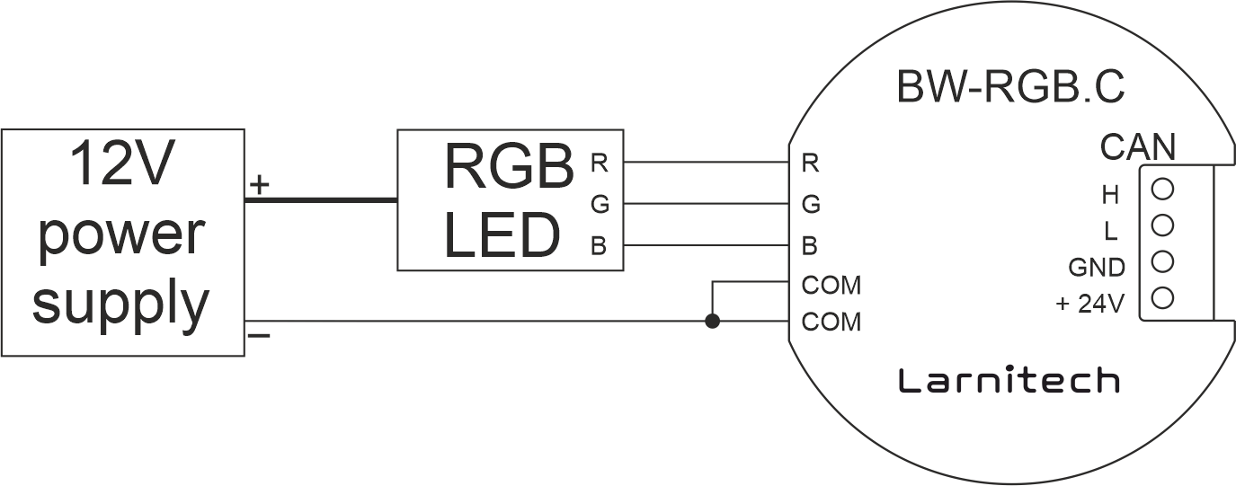
Пример подключения
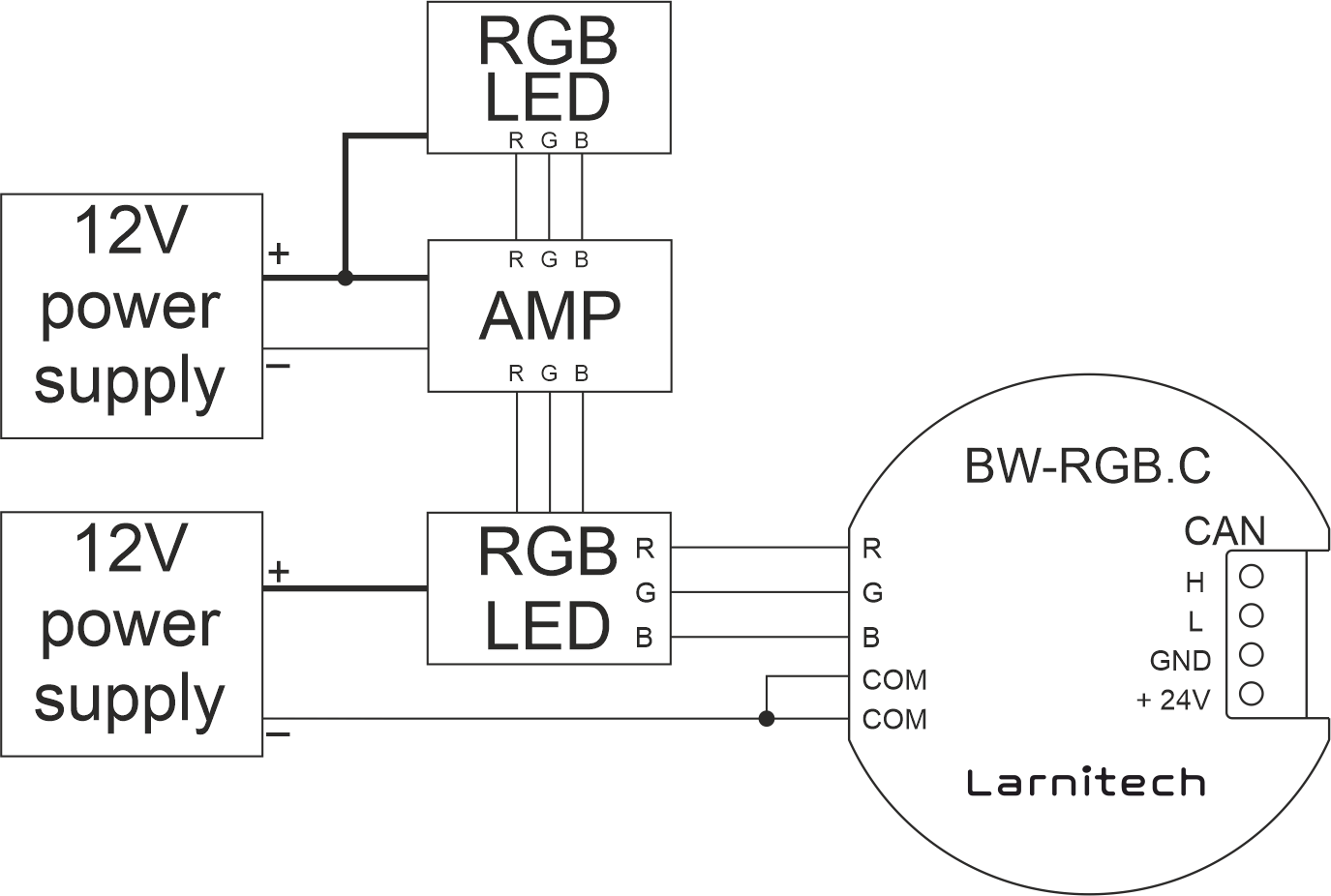
Пример подключения RGB светодиодов с усилителем
Параметры модуля
| Parameter name | Value |
|---|---|
| Output channels qty | 3 |
| Input voltage | 11.5 … 25V |
| Current type | DC |
| Adjustment type | PWM |
| Max load per channel | 1A (12W at 12V) |
| Max load per device | 3A (36W at 12V) |
| Power supply | 11.5 … 27.5 V DC from CAN |
| Max current(24V) | 25 mA |
| Bus type | CAN (4-wire) |
| Equipment installation type | Free |
| Case material | ABS |
| Protection | IP40 |
| Temperature range | -10 … +50 °C |
| Size | 45x42x14 mm |
| Weight | 25 g |
Порядок установки и подключения модуля
- Connect the outputs.
- Connect the CAN connector.
- Configure the module using LT setup.
- Apply power to the load.
- Check all equipment for proper operation.
Module shut-off and deinstallation procedure
- Disconnect the power from the load.
- Disconnect the CAN connector.
- Disconnect the outputs.
HW settings
| Name | Type, range | SUBID | Default | Description |
|---|---|---|---|---|
| dm | char[3] | 98 | 'RGB' | Each char is responsible for the type of a particular channel, RGB takes 3 channels
Example: dm='DDD' |
| def | integer 0-250 | 1-3 | 100 | The default brightness level in case of a power reset (1..250). Example: def=250 |
| min | integer 0-100 | 1-3 | 0 | Minimum dimming level, example: min=10 |
| max | integer 0-100 | 1-3 | 100 | Maximum dimming level, example max=95 |
| runtime | integer 0-100 | 98 | 5 | Runtime is the speed of changing the brightness(measured in seconds). Example: runtime=15 |
| f | integer 1-1000 | 98 | 500 | It is frequency (measured in Hz); Example: f=500 |
1<item addr="355:1" auto-period="600" cfgid="175" name="Dimmer" type="dimer-lamp" uniq_id="68"/>
2<item addr="355:2" auto-period="600" cfgid="175" name="Dimmer" type="dimer-lamp" uniq_id="69"/>
3<item addr="355:3" auto-period="600" cfgid="175" name="Dimmer" type="dimer-lamp" uniq_id="70"/>
4<item addr="355:98" cfgid="175" hw="dm='DDD' f=1000 runtime=20" name="Temperature" system="yes" type="temperature-sensor" uniq_id="47"/>