Difference between revisions of "BW-SW24V/ru"
Jump to navigation
Jump to search
(Created page with "#Отсоедините разъем CAN #Отсоедините входы и выходы.") |
(Created page with "==Установки HW== {|class="wikitable" |- !Название!!Тип, диапазон!!SUBID!!По умолчанию!!Описание |- |in||символ[6]||98||'BB...") |
||
| Line 68: | Line 68: | ||
| − | ==HW | + | ==Установки HW== |
{|class="wikitable" | {|class="wikitable" | ||
|- | |- | ||
| − | ! | + | !Название!!Тип, диапазон!!SUBID!!По умолчанию!!Описание |
|- | |- | ||
| − | |in|| | + | |in||символ[6]||98||'BBBBBB'||Каждый символ отвечает за тип конкретного канала |
| − | *'B'- | + | *'B'-Кнопка, кнопка звонка; |
| − | *'C'- | + | *'C'-Кнопка (инверсия), кнопка звонка (инверсия) (в обычном состоянии - закрыто); |
*'-'-none, nothing is connected. | *'-'-none, nothing is connected. | ||
Example: in='BB-C-C' | Example: in='BB-C-C' | ||
|- | |- | ||
| − | |out|| | + | |out||символ[6]||98||'BBBBBB'||Each char is responsible for the type of a particular channel |
*'B'- LED of button; | *'B'- LED of button; | ||
*'I'- inverted LED of button; | *'I'- inverted LED of button; | ||
*'L'- Lamp; | *'L'- Lamp; | ||
*'M'- inverted Lamp; | *'M'- inverted Lamp; | ||
| − | *'-'- | + | *'-'-элементы отсутствуют, ничего не подключено. |
| − | + | Пример: out='BBLILI' | |
|- | |- | ||
| − | |common|| | + | |common||символ||98||'C'||Светодиод с общим проводом |
| − | *'C'- | + | *'C'- Использовать Out0 как общий катод; |
| − | *'A'- | + | *'A'- Использовать Out0 как общий анод; |
| − | + | Пример: common='C' | |
|} | |} | ||
Revision as of 13:11, 9 January 2022
| BW-SW24V.C | |||||||||
|---|---|---|---|---|---|---|---|---|---|
 | |||||||||
| |||||||||
| |||||||||
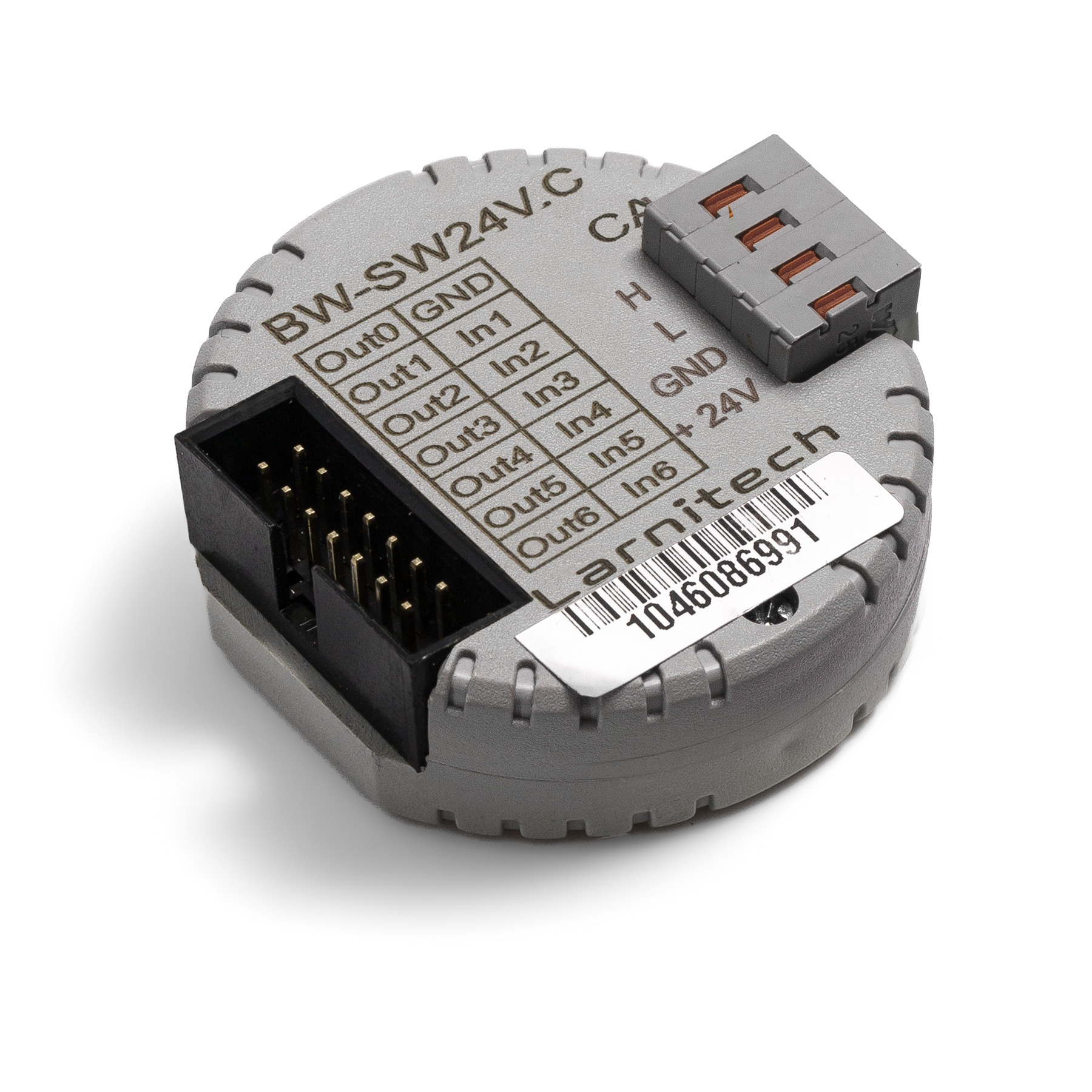
МОДУЛЬ ВХОДОВ КНОПОК 24 В
Модуль применяется для подключения кнопок 24 В с задней светодиодной подсветкой или без нее.
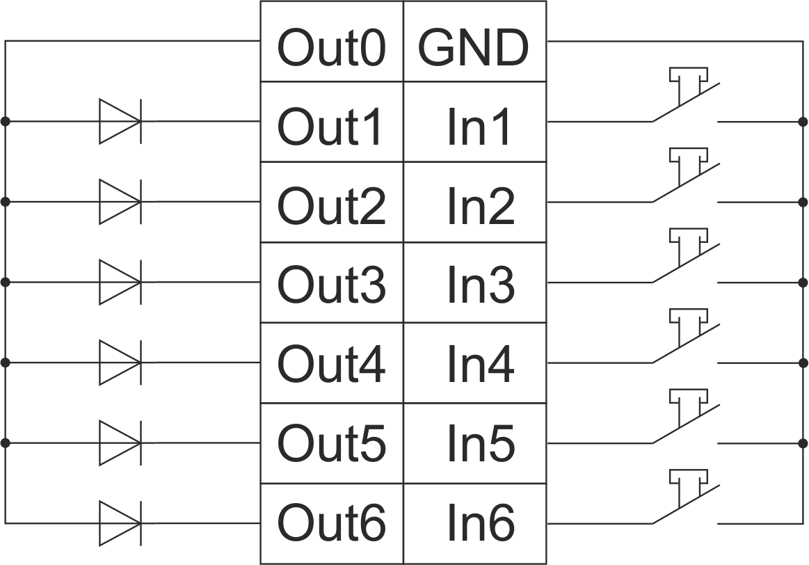
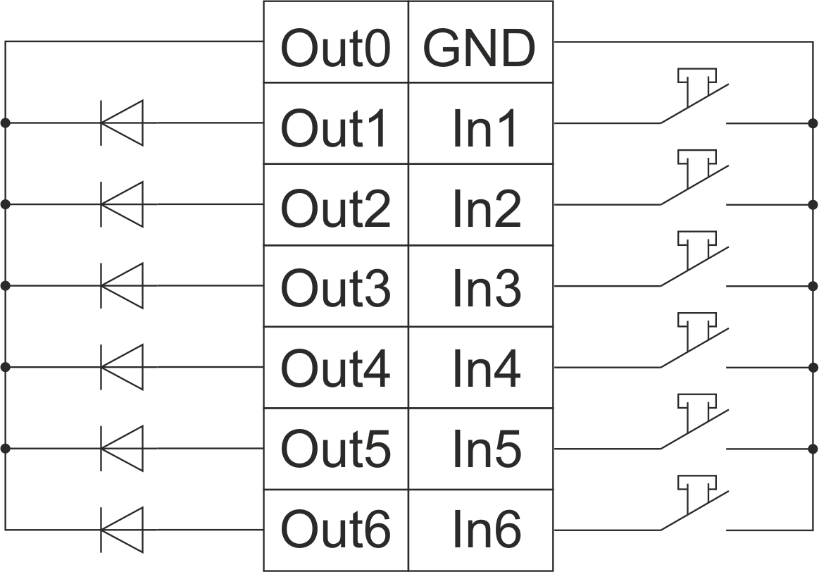
Пример подключения
Пример HW:
1hw="in='BBBBBB' out='BBBBBB' common='A'"
6 светодиодных кнопок с общим проводом и общим анодом 24 В постоянного тока
common='A' – использовать Out0 как общий анод
Пример HW:
1hw="in='BBBBBB' out='BBBBBB' common='C'"
6 светодиодных кнопок с общим проводом и общим катодом 24 В постоянного тока common='C' – использовать Out0 как общий катод
Параметры модуля
| Parameter name | Value |
|---|---|
| Input channels qty | 6 |
| Buttons | 6 |
| LED Buttons | 6 |
| Output channels qty | 6 |
| Backlight voltage | 11.5 … 27.5 V DC (from CAN) |
| Power supply | 11.5 … 27.5 V DC from CAN |
| Max current(24V) | 30 mA |
| Bus type | CAN (4-wire) |
| Equipment installation type | Free |
| Case material | ABS |
| Protection | IP40 |
| Temperature range | -10 … +50 °C |
| Size | 45x42x14 mm |
| Weight | 25 g |
Порядок установки и подключения модуля
- Подключите входы и выходы.
- Подсоедините разъем шины CAN.
- Настройте модуль с помощью LT SETUP.
- Проверьте все оборудование на правильность работы.
Отключение модуля и процедура демонтажа
- Отсоедините разъем CAN
- Отсоедините входы и выходы.
Установки HW
| Название | Тип, диапазон | SUBID | По умолчанию | Описание |
|---|---|---|---|---|
| in | символ[6] | 98 | 'BBBBBB' | Каждый символ отвечает за тип конкретного канала
Example: in='BB-C-C' |
| out | символ[6] | 98 | 'BBBBBB' | Each char is responsible for the type of a particular channel
Пример: out='BBLILI' |
| common | символ | 98 | 'C' | Светодиод с общим проводом
Пример: common='C' |