BW-SW24V

From Larnitech wiki page
Revision as of 12:54, 9 January 2022 by Rusanov (talk | contribs) (Created page with "BW-SW24V")
(diff) ← Older revision | Latest revision (diff) | Newer revision → (diff)
Jump to navigation Jump to search
Other languages:
English • ‎русский
Revision:
/B
/C


BW-SW24V.C
BW-SW24VC.png
Output ports
Number of switched channels6
Input ports
Number of inputs6
Number of buttons6
Number of LED buttons6
Other
Supply voltage11.5...27.5 V DC
Dimentions45x42x14 mm


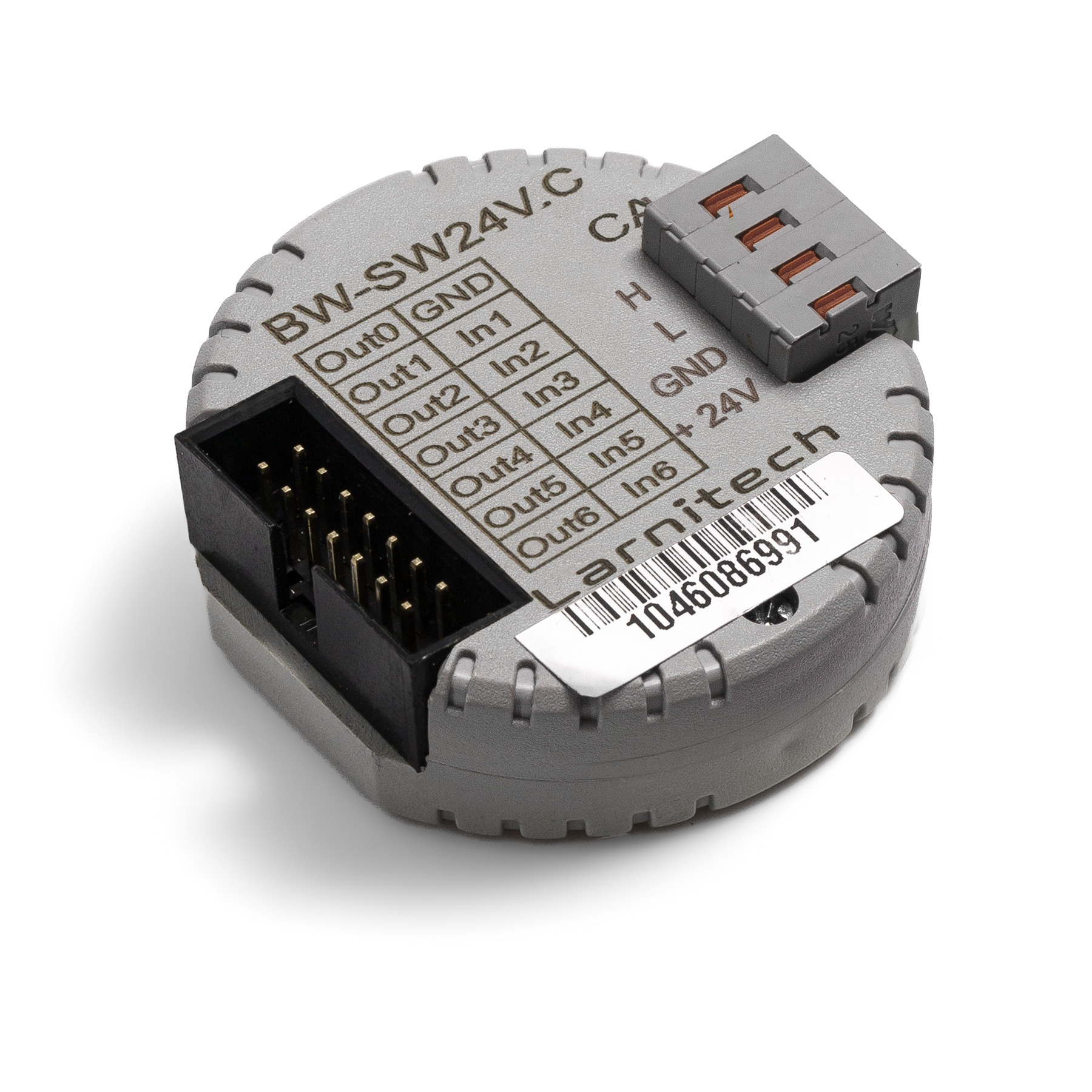
24V BUTTONS INPUT MODULE

This module is used to connect 24V buttons w/wo LED backlighting.


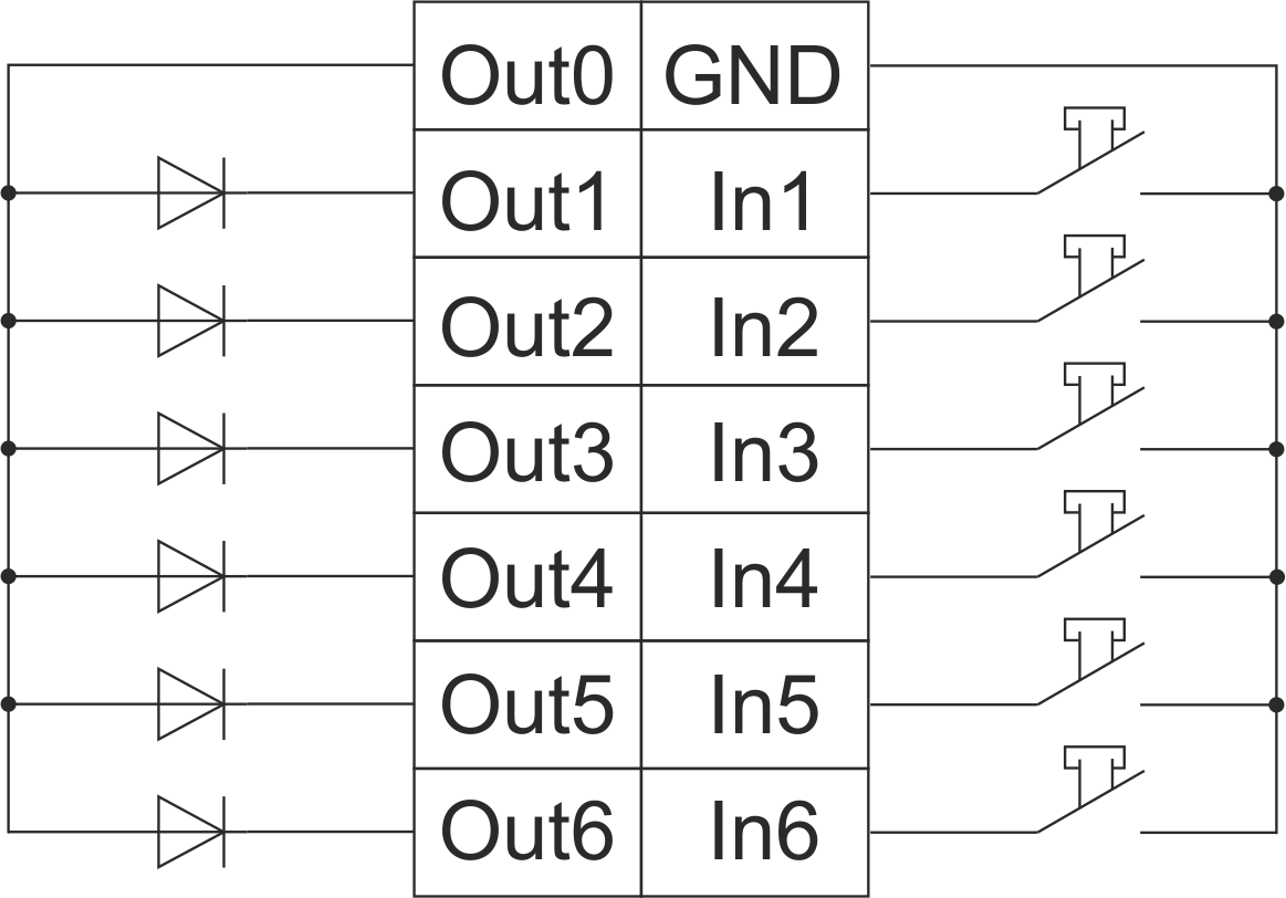
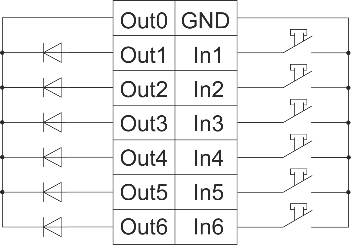
Example of connection

SW24VC EXA1.png
HW example:

1hw="in='BBBBBB' out='BBBBBB' common='A'"

6 common-wire buttons with common-anode 24 V DC LEDs common='A' – use Out0 as common anode SW24VC EXA2.png
HW example:

1hw="in='BBBBBB' out='BBBBBB' common='C'"

6 common-wire buttons with common-catode 24 V DC LEDs common='C' – use Out0 as common catode

Module parameters

Parameter name Value
Input channels qty 6
Input/output channels qty
0-10 input port quantity
Buttons 6
LED Buttons 6
Number of sensor inputs
Number of dry contact inputs
RS485 ports qty
RS232 ports qty
UART ports qty
M-BUS port quantity
Pulse inputs quantity
DALI ports qty
DALI-line voltage supply
Peak current of DALI-line power supply
Peak current in DALI-line
Maximum DALI devices quantity
Dimming channels qty
Output channels qty 6
0-10 output port quantity
Analog output channels qty
Output
Digital line maximum length
Discrete input channels qty
Digital input channels qty
Speakers
Max power output audio channel
Camera
IR lighting
Card reader
Connection type
Protocols
Backlight voltage 11.5 … 27.5 V DC (from CAN)
Load type
Dimmer load type
Supported sensors
Input voltage
Current type
Adjustment type
Max load
Min load
Max load per channel
Max load per group
Max load per device
Control parameters
Angle of vision IR °
Angle of motion °
Temperature measuring range °C
Humidity measuring range
Dimmer type
Dimming type
Voltage that may be applied to the input channels
Max output switching voltage
Max output switching current
Power supply 11.5 … 27.5 V DC from CAN
Max current(24V) 30 mA
Max current(13V)
Max detection distance
Max IR distance
Max BT distance
Max current
Relay
Data transfer speed
Permissible section of power supply cable to connect in socket:
Sensors VCC output
Sensors max VCC current
R1-R2 inputs max current
Push-button/reed switches line recommended length
Temperature sensor line max length
Sensor cable length
Sensors line max length
Bus type CAN (4-wire)
Compatible with
Output voltage
Output current
Equipment installation type Free
Mounting
Max cabel lenght
Case material ABS
Protection IP40
Temperature range -10 … +50 °C
Size 45x42x14 mm
Weight 25 g
* -
** -
*** -
1 -
2 -
3 -


Module installation and connection procedure

  1. Connect the inputs and outputs.
  2. Connect the CAN connector.
  3. Configure the module using LT setup.
  4. Check all equipment for proper operation.

Module shut-off and deinstallation procedure

  1. Disconnect the CAN connector.
  2. Disconnect the inputs and outputs..


HW settings

Name Type, range SUBID Default Description
in char[6] 98 'BBBBBB' Each char is responsible for the type of a particular channel
  • 'B'-Button, button of bell a type;
  • 'C'-Inverted button, inverse button of a bell type (for normally-closed);
  • '-'-none, nothing is connected.

Example: in='BB-C-C'

out char[6] 98 'BBBBBB' Each char is responsible for the type of a particular channel
  • 'B'- LED of button;
  • 'I'- inverted LED of button;
  • 'L'- Lamp;
  • 'M'- inverted Lamp;
  • '-'-none, nothing is connected.

Example: out='BBLILI'

common char 98 'C' LED common wire
  • 'C'- Use Out0 as common catode;
  • 'A'- Use Out0 as common anode;

Example: common='C'