Difference between revisions of "DW-BC03/ru"
Jump to navigation
Jump to search
(Created page with "==Изображение модуля==") |
(Created page with "==Подключение приводов штор/жалюзи/ставней==") |
||
| Line 45: | Line 45: | ||
[[File:BC03C VIEW.png|500px]] | [[File:BC03C VIEW.png|500px]] | ||
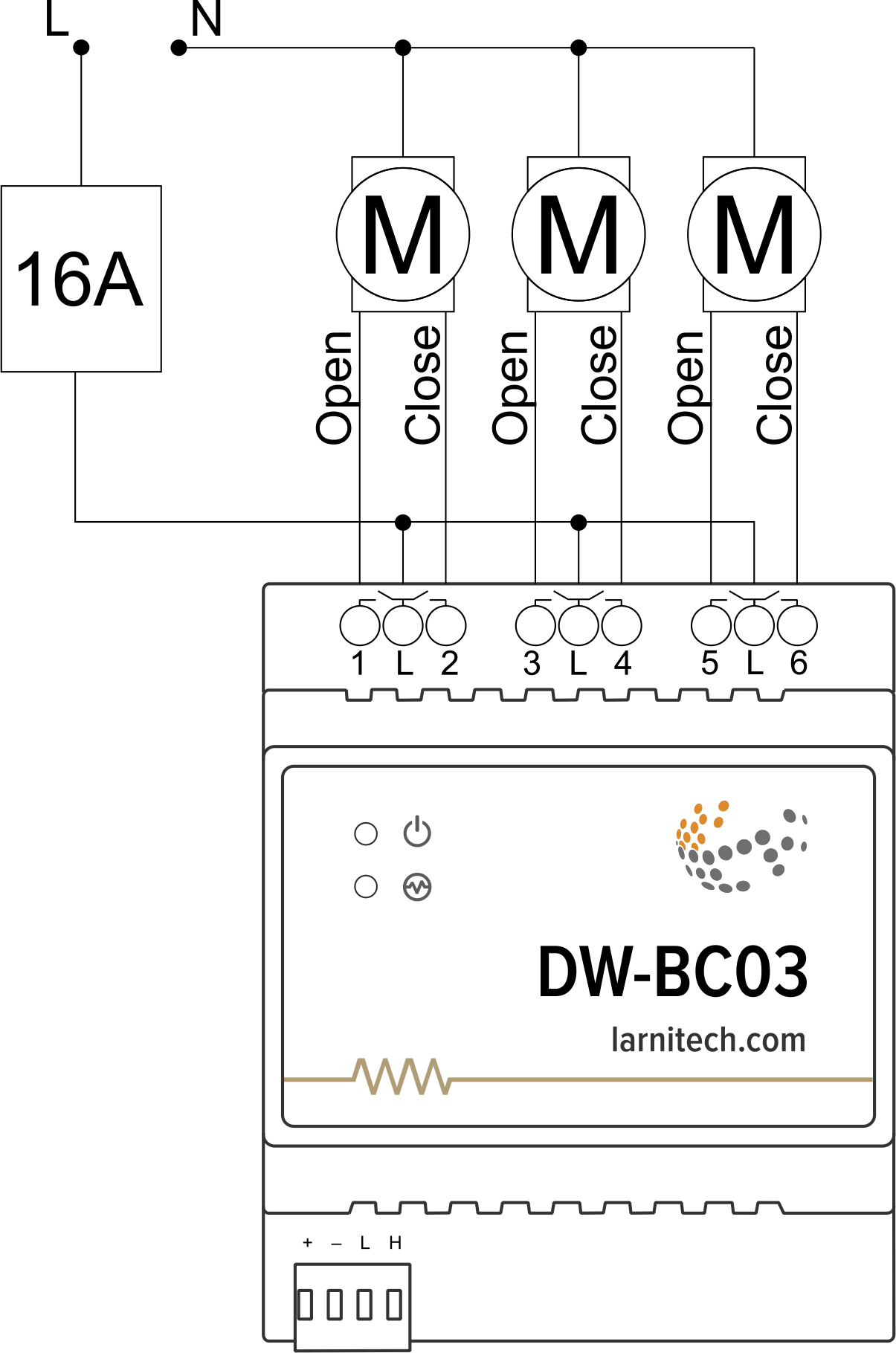
| − | == | + | ==Подключение приводов штор/жалюзи/ставней== |
[[File:BC03C EXA.png|500px]] | [[File:BC03C EXA.png|500px]] | ||
Revision as of 13:35, 6 January 2022
| DW-BC03.C | |||||||
|---|---|---|---|---|---|---|---|
 | |||||||
| |||||||
3-Х КАНАЛЬНЫЙ МОДУЛЬ ДЛЯ УПРАВЛЕНИЯ ПРИВОДОМ ЖАЛЮЗИ
Этот модуль обеспечивает управление шторами, экранами проектора, клапанами или другими электродвигателями.
Функции
- Поддерживаемые типы нагрузки:
- шторы с силовым/слаботочным управлением
- 1/2-х полюсные клапаны
- Защита от перегрузки
- Встроенный датчик тока
ВНИМАНИЕ! Все работы, связанные с установкой, подключением, настройкой, обслуживанием и поддержкой оборудования, должны выполняться только квалифицированным персоналом, обладающим достаточными навыками и опытом работы с электрооборудованием! Во избежание риска возгорания, поражения электрическим током, повреждения системы и/или травм, установка и сборка системы должны выполняться в соответствии с указаниями, перечисленными ниже:
- все работы по подключению должны выполняться при выключенном питании;
- необходимо использовать соответствующие инструменты и средства индивидуальной защиты от поражения электрическим током;
- запрещается использовать поврежденные кабели, провода и разъемы;
- избегайте перегиба проводов и кабелей;
- не прилагайте чрезмерных усилий к проводам путем их перегиба или слишком сильного сжатия: внутренние проводники кабелей и проводов могут быть оголены или повреждены;
- не используйте для подключения разъемы с плохими контактами;
- не превышайте параметры предельной нагрузки, указанные в инструкции;
- сечение питающих проводов зависит от требований к пределу плотности тока, типу изоляции и материалу проводов. Недостаточное сечение провода может привести к перегреву кабеля и возгоранию.
Когда питание включено, НИКОГДА:
- не подключайте/отключайте разъемы;
- не открывайте модули и датчики.
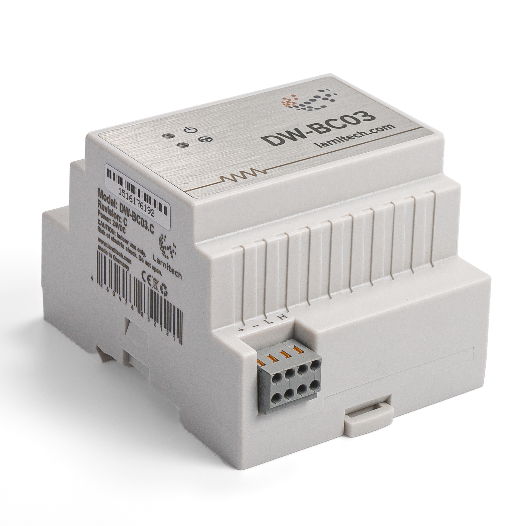
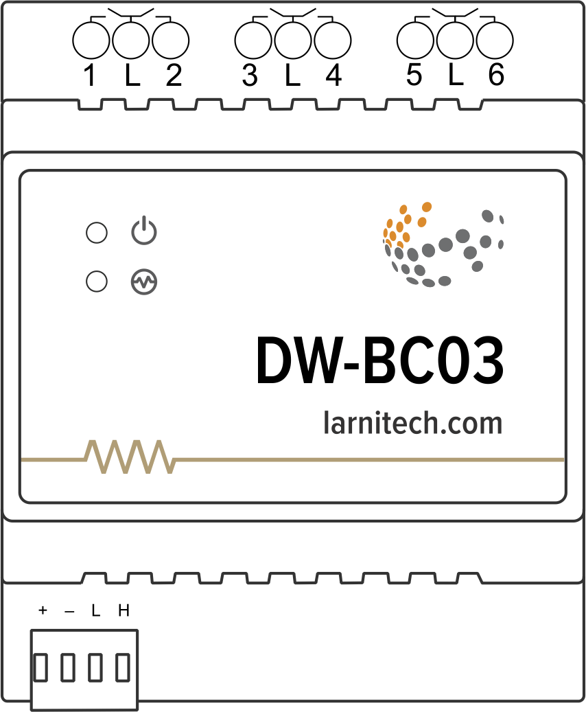
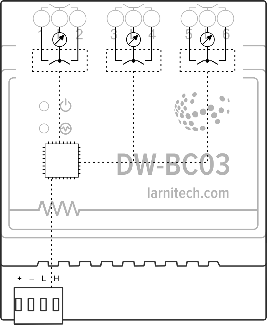
Изображение модуля
Подключение приводов штор/жалюзи/ставней
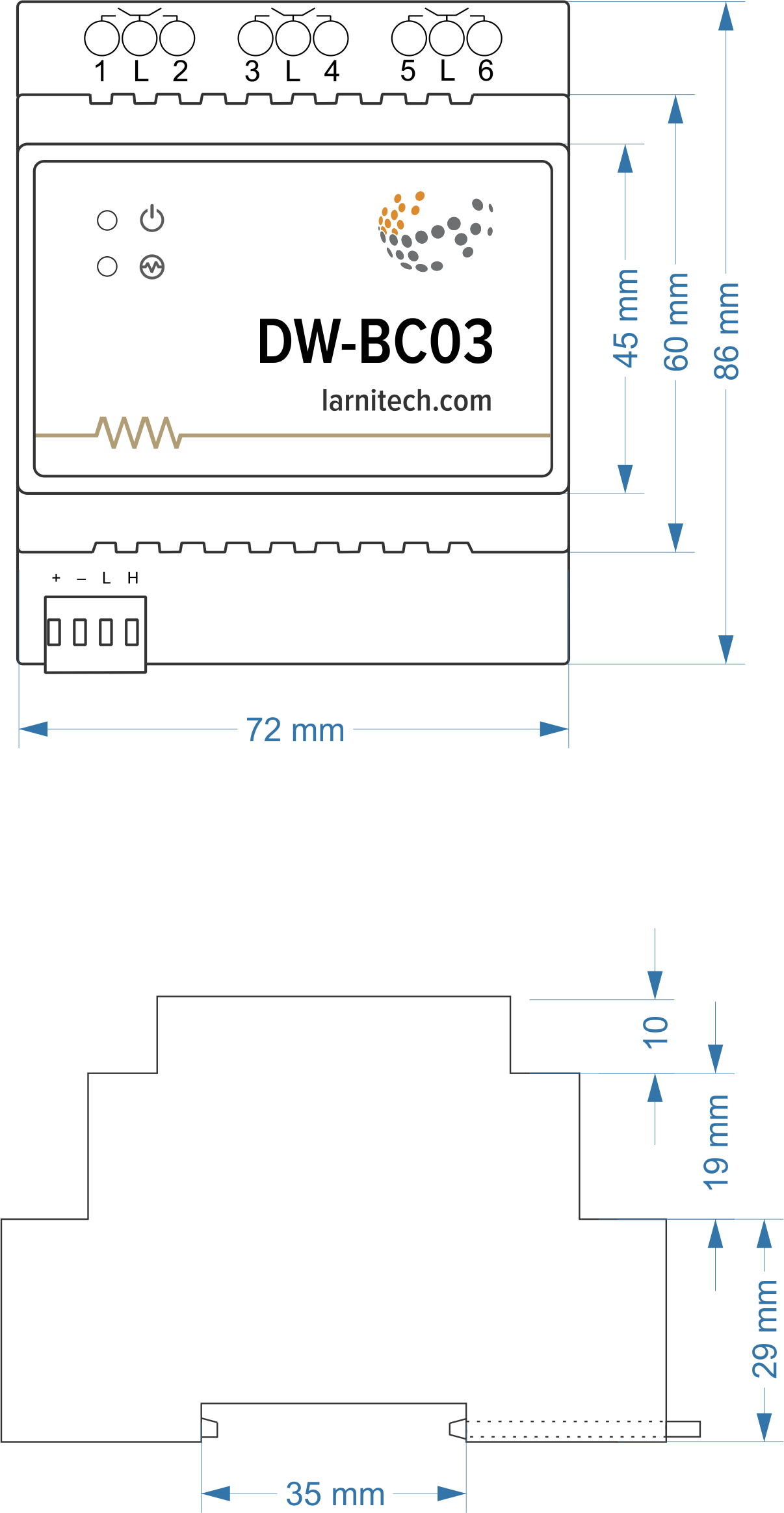
Module dimensions
Internal layout
Module parameters
| Parameter name | Value |
|---|---|
| Output channels qty | 3 |
| Input voltage | 0-250 V AC/DC |
| Current type | AC/DC |
| Max load per channel | 5A |
| Power supply | 11.5 … 27.5 V DC from CAN |
| Max current(24V) | 55 mA |
| Permissible section of power supply cable to connect in socket: single-conductor cable multiple-conductor cable tipped multiple-conductor cable |
0.5 … 4mm2 0.5 … 4mm2 0.5 … 2.5mm2 |
| Bus type | CAN (4-wire) |
| Equipment installation type | DIN rail (EN 60715) |
| Case material | ABS |
| Protection | IP40 |
| Temperature range | -10 … +50 °C |
| Size | 4U, 69x110x58 mm |
| Weight | 85 g |
Indication of module operation
Bootloader
| Indicator | Status | Description |
|---|---|---|
| Device in bootloader | ||
| Downloading firmware | ||
| Flashing firmware |
Firmware
| Indicator | Status | Description |
|---|---|---|
| Identification | ||
| Operational mode | ||
Error | ||
| Lost connection to server | ||
| Overheat | ||
| Overload |
Module installation and connection procedure
- Install the module in the switchboard on the DIN rail and fix it with the special latch on the module base.
- Connect the CAN connector.
- Connect the channels.
- Configure the module using LT setup.
- Apply power to the load.
- Check all equipment for proper operation.
Module shut-off and deinstallation procedure
- Disconnect the power from the load.
- Disconnect the channels.
- Disconnect the CAN connector.
- Remove the module from the DIN rail, releasing the latch at the bottom of the module base.
HW settings
| Name | Type, range | SUBID | Default | Description |
|---|---|---|---|---|
| runtime | integer 0-100 | 1-6 | 15 | runtime is the open/close time in seconds, is used for jalousie, gate, valve(2 pole); Example: runtime=15 |
| runtimeopen | integer 0-60000 | Blinds subId | – | Runtimeopen is the open time in miliseconds, is used for blinds; Example: runtimeopen=15000 |
| runtimeclose | integer 0-60000 | Blinds subId | – | Runtimeclose is the close time in miliseconds, is used for blinds; Example: runtimeclose=15000 |
| hold | integer 0-10000 | 1-6 | 500 | hold is the bridging time in miliseconds, is used for gate and jalousie (by default hold is the same as runtime), lock; Example: hold=3500 |
| current | integer 0;1 | 1;3;5 | 1 |
0 – Disable current sensor. 1 – Use current sensor to detect blinds movement. |
| out_l_protect_on | integer | 1;3;5;98 | 1000 | Overload protection threshold (mA). (Setting to 98 subId applies to all three current sensors.) |
| def | string 'ON' | 1-6 | 'OFF' | Def is the element status is set after restart, is used for lamp, heating, valve(1 pole); Example: def='ON' |
| stop | Char 'R' | 1-5 | – | (for 2-pole gate and blinds) If it is declared then by Stop command during the motion, the same impulse appears as it was at the beginning of the motion. Pole, an which the stop-impules is formed, is defined by the parameter Stop value. If it is 'r' or 'R' then stop-impulse is produced on the opposite to the start-impulse pole. If any other value is delcared (e.g., 'd' ) then the stop-impulse is on the same pole. If a Runtime passed after the beginning of the motion then the stop-impulse is not formed. Example: stop='r' |
| out | char[6] | 98 | 'PPP' | Each char is responsible for the type of a particular channel
Example: dm='BGV' |
1<item addr="449:1" cfgid="46" name="Jalousie" sub-type="120" type="jalousie" uniq_id="4069"/>
2<item addr="449:3" cfgid="46" name="Gate" sub-type="120" type="gate" uniq_id="4077" hw="runtime=55"/>
3<item addr="449:5" cfgid="46" name="Valve" type="valve" uniq_id="4078"/>
4<item addr="449:30" cfgid="46" name="Current" system="yes" type="current-sensor" uniq_id="4072"/>
5<item addr="449:31" cfgid="46" name="Current" system="yes" type="current-sensor" uniq_id="4073"/>
6<item addr="449:32" cfgid="46" name="Current" system="yes" type="current-sensor" uniq_id="4074"/>
7<item addr="449:97" cfgid="46" name="Temperature" system="yes" type="temperature-sensor" uniq_id="4075"/>
8<item addr="449:98" cfgid="46" hw="out='BGV'" name="Temperature" system="yes" type="temperature-sensor" uniq_id="4076"/>