Difference between revisions of "DW-DALI.A/ru"
(Created page with "#Отсоедините разъем питания (2). #Отсоедините разъем шины DALI (1). #Отсоедините разъем шины CAN (4). #Сни...") |
(Created page with "==Настройка оборудования== Для настройки и управления модулем DW-DALI на свой смартфон или планшет...") |
||
| Line 115: | Line 115: | ||
#Снимите модуль с DIN-рейки, освободив защелку, расположенную в нижней части основания модуля. | #Снимите модуль с DIN-рейки, освободив защелку, расположенную в нижней части основания модуля. | ||
| − | == | + | ==Настройка оборудования== |
| − | + | Для настройки и управления модулем DW-DALI на свой смартфон или планшет необходимо установить программное обеспечение Larnitech, которое можно приобрести в [https://itunes.apple.com/us/app/larnitech/id1108457530?mt=8 App Store] и [https://play.google.com/store/apps/details?id=com.larnitech Play Market]. После установки приложения следуйте '''Инструкциям по настройке системы'''. | |
==Fault diagnostics and handling== | ==Fault diagnostics and handling== | ||
Revision as of 14:27, 7 January 2022
| DW-DALI.A | |||||||
|---|---|---|---|---|---|---|---|
 | |||||||
| |||||||
Введение
Руководство по установке модуля DW-DALI.A описывает порядок его установки, сборки, эксплуатации и настройки. При работе с системой необходимо строго соблюдать все требования, изложенные в данном руководстве. Несоблюдение этих требований может привести к повреждению устройства, его выходу из строя, поражению электрическим током, возгоранию и другим последствиям.
ВНИМАНИЕ! Все работы, связанные с установкой, подключением, настройкой, обслуживанием и поддержкой оборудования, должны выполняться только квалифицированным персоналом, обладающим достаточными навыками и опытом работы с электрооборудованием! Во избежание риска возгорания, поражения электрическим током, повреждения системы и/или травм, установка и сборка системы должны выполняться в соответствии с указаниями, перечисленными ниже:
- все работы по подключению должны выполняться при выключенном питании;
- необходимо использовать соответствующие инструменты и средства индивидуальной защиты от поражения электрическим током;
- запрещается использовать поврежденные кабели, провода и разъемы;
- избегайте перегиба проводов и кабелей;
- не прилагайте чрезмерных усилий к проводам путем их перегиба или слишком сильного сжатия: внутренние проводники кабелей и проводов могут быть оголены или повреждены;
- не используйте для подключения разъемы с плохими контактами;
- не превышайте параметры предельной нагрузки, указанные в инструкции;
- сечение питающих проводов зависит от требований к пределу плотности тока, типу изоляции и материалу проводов. Недостаточное сечение провода может привести к перегреву кабеля и возгоранию.
Когда питание включено, НИКОГДА:
- не подключайте/отключайте разъемы;
- не открывайте модули и датчики.
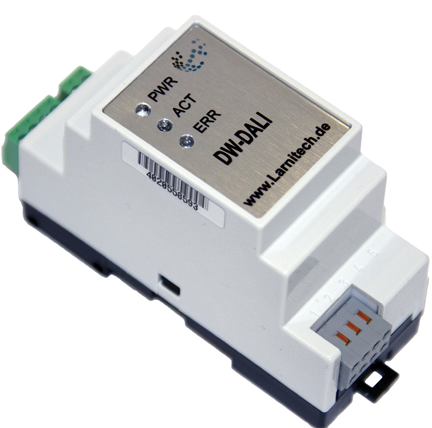
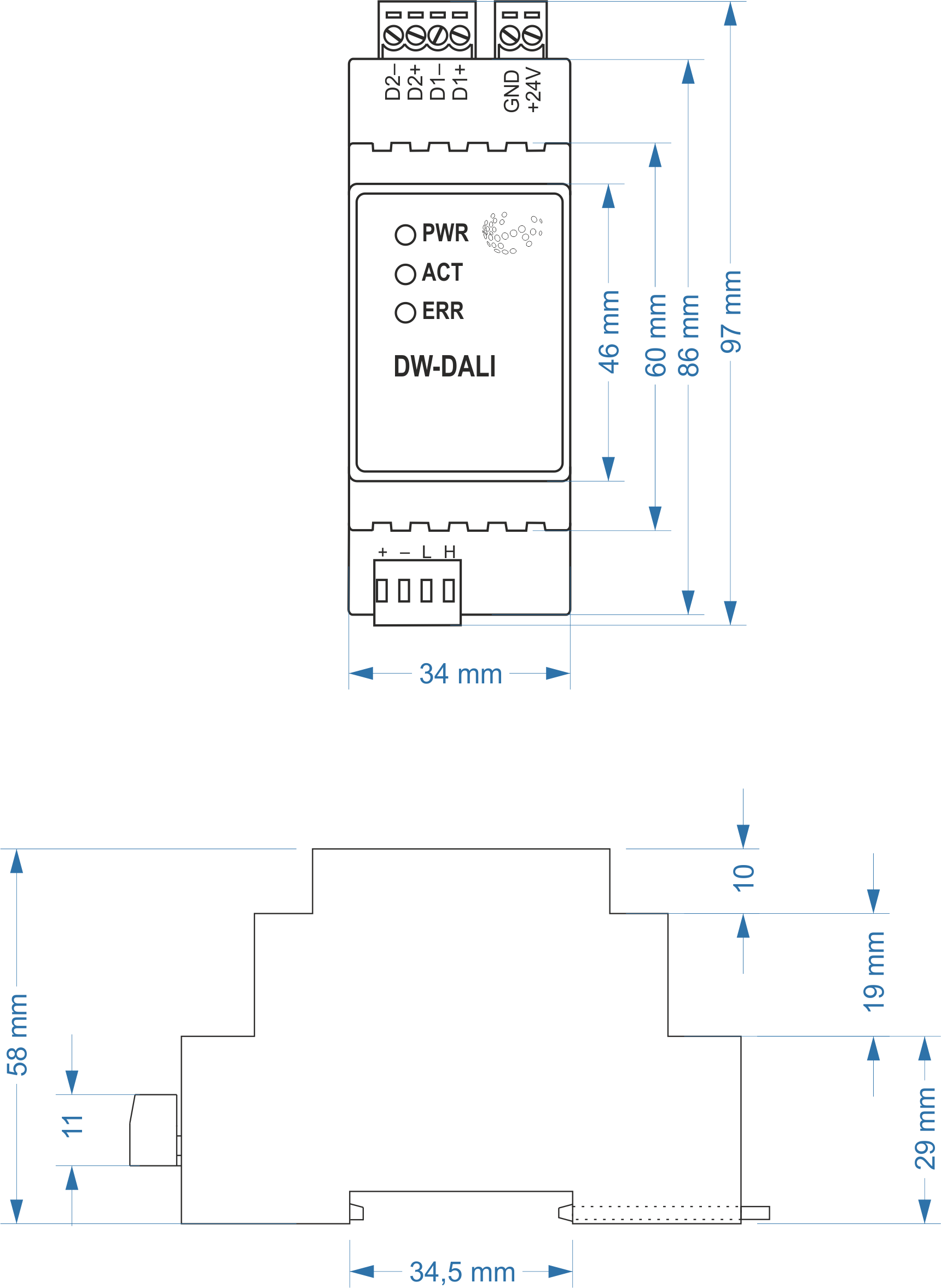
Размеры модуля
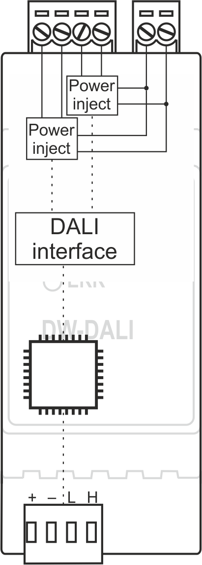
Внутренняя компоновка
Module configuration and correct use
Module correct use
Модуль DW-DALI.A предназначен для использования в составе проводной системы Larnitech Smart House. DW-DALI.A должен использоваться для обмена данными между устройствами, подключенными к шине CAN, и такими устройствами, как электронные балласты и диммеры, поддерживающими интерфейс DALI (Digital Addressable Lighting Interface).
Комплектность
В комплект поставки входят:
| Parameter name | Value |
|---|---|
| DALI ports qty | 2 |
| DALI-line voltage supply | 23.5 – 24.5 V DC |
| Peak current of DALI-line power supply | 1A |
| Peak current in DALI-line | 300 mА |
| Maximum DALI devices quantity | 641 |
| Power supply | 11.5 … 27.5 V DC from CAN |
| Max current(24V) | 30 mA |
| Bus type | CAN (4-wire) |
| Equipment installation type | DIN rail (EN 60715) |
| Case material | ABS |
| Protection | IP40 |
| Temperature range | -10 … +50 °C |
| Size | 2U, 35x97x58 mm |
| Weight | 75g |
Общая структура модуля
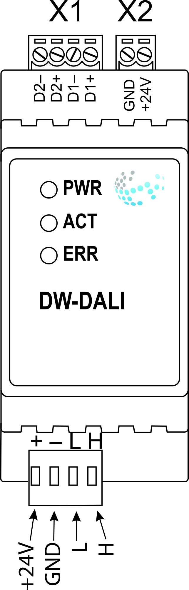
В нижней части корпуса модуля находится разъем (3) для подключения к сети Умного дома по шине CAN.
The physical configuration and contact point assignment of each connector are shown in table
| Connector | Contact | Assignment |
|---|---|---|
1 DALI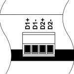 |
D1+ D1- D2+ D2- |
DALI1 bus DALI2 bus |
| 2 DALI power supply |
+24V GND |
+24V — DALI bus power supply GND — common |
| 3 Module indicating unit |
The scenario for module indicating unit is shown below | |
| 4 CAN |
VCC GND L H |
VСС — +24V power supply of CAN-bus GND — common L — CAN-L data bus H — CAN-H data bus |
| Indicator | Status | Description |
|---|---|---|
| Power | Power | |
| Power not available | ||
| Activity | Data communication | |
| Data communication not available | ||
| Error | No errors | |
| Overheating | ||
| The data has not been transferred via the CAN bus for at least 5 minutes. | ||
| No power on the DALI bus or over current (more then 180 mA) on DALI bus. If over current is at both bus blinking twice in half a second. |
Сборка и установка модуля
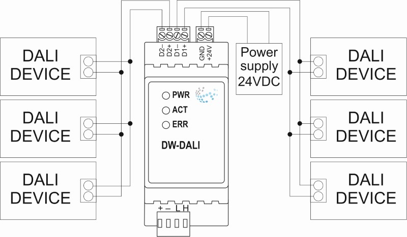
Перед подключением модуля необходимо определить место для установки модуля. Примечание: модуль необходимо устанавливать рядом с источником питания 24 В.
Типовая схема подключения модуля DW-DALI.A
Порядок установки и подключения модуля
ВНИМАНИЕ! Необходимо точно следовать рекомендациям, перечисленным в разделе «Требования безопасности» данного руководства.
- Установите модуль в распределительный щит на DIN-рейку и закрепите специальной защелкой, расположенной на основании модуля..
- Подсоедините разъем шины CAN (4).
- Подсоедините разъем шины DALI (1).
- Подключите разъем питания шины DALI (2).
- Включите источник питания модуля (24 В).
Отключение модуля и процедура демонтажа
- Отсоедините разъем питания (2).
- Отсоедините разъем шины DALI (1).
- Отсоедините разъем шины CAN (4).
- Снимите модуль с DIN-рейки, освободив защелку, расположенную в нижней части основания модуля.
Настройка оборудования
Для настройки и управления модулем DW-DALI на свой смартфон или планшет необходимо установить программное обеспечение Larnitech, которое можно приобрести в App Store и Play Market. После установки приложения следуйте Инструкциям по настройке системы.
Fault diagnostics and handling
The following are some possible faults and ways of fault handling. If you have any difficulty, or face the fault undeclared here, please contact the Technical Support: http://www.larnitech.com/support/ or support@larnitech.com. There are also some tips in the FAQ section at our website http://www.larnitech.com/faq/
System Setup Instruction
Each DALI bus can use 40 DALI devices. Together DALI buses for one DW-DALI.A can use 64 DALI devices. Address DALI device must be from 1 to 63. To add DALI devices to DALI bus, add «hw» to tag with SubID 98, hw=”bus1=’1,2,3,…’ bus2=’1,2,3,…’ “:
- bus1 — first DALI bus data;
- bus2 — second DALI bus data;
- 1,2,3 — address DALI devices.
Configuring DALI device settings(set from scripts):
— setStatus(ID:SID, {0xC0, ADDR}) – set address DALI devices, need to connect one DALI device on DALI bus data:
- ID:SID — address DALI bus data (com-port in logic.xml);
- 0xC0 — command for set address DALI devices;
- ADDR — address DALI device.
— setStatus(ID:SID, {0xD4, ADDR, LEVEL}) — set default brightness:
- ID:SID — address DALI bus data (com-port in logic.xml);
- 0xD4 — command for set default brightness DALI devices;
- ADDR — address DALI device;
- LEVEL — brightness level, 0…250.
— setStatus(ID:SID, {0xD3, ADDR, TIME}) — set the brightness change time:
- ID:SID — address DALI bus data (com-port in logic.xml);
- 0xD3 — command for set the brightness change time DALI devices;
- ADDR — address DALI device;
- TIME — brightness change time, in seconds.
— setStatus(ID:SID, {0xD1, ADDR, LEVEL}) — set minimum brightness:
- ID:SID — address DALI bus data (com-port in logic.xml);
- 0xD1 — command for set minimal brightness DALI devices;
- ADDR — address DALI device;
- LEVEL — brightness level, 0…250.
— setStatus(ID:SID, {0xD0, ADDR, LEVEL}) — set maximum brightness:
- ID:SID — address DALI bus data (com-port in logic.xml);
- 0xD0 — command for set maximum brightness DALI devices;
- ADDR — address DALI device;
- LEVEL — brightness level, 0…250.
HW Settings
| Name | Type, range | SUBID | Default | Description |
|---|---|---|---|---|
| bus1 | string | 98 | — |
Example: 1hw="bus1='1-30'" — create in logic 30 dimmer l
2hw="bus1='1L-30'" — create in logic 30 l
3hw="bus1='1L-10,20-35'" — create in logic 10 lamp and 15 dimmer l
4hw="bus1='6,35,2,1,54'" — create in logic 5 dimmer l
|
| bus2 | string | 98 | — |
Example: 1hw="bus2='1-30'" — create in logic 30 dimmer l
2hw="bus2='1L-30'" — create in logic 30 l
3hw="bus2='1L-10,20-35'" — create in logic 10 lamp and 15 dimmer l
4hw="bus2='6,35,2,1,54'" — create in logic 5 dimmer l
|
| def | string 'ON' | certain SubID | 'OFF' | def is the element status is set after restart
1hw="def='ON'"
|
| min | integer (0…100) | certain SubID | 0 | minimum dimming level, 0..100;
Example: 1hw="min=30"
|
| max | integer (0…100) | certain SubID | 100 | maximum dimming level, 0..100;
Example: 1hw="max=80"
|
| [hill] | string | certain SubID | — | abrupt change at the beginning, gradual change at the end
Example: 1hw="min=30 max=80 hill"
|
| [pit] | string | certain SubID | — | gradual change at the beginning, abrupt change at the end
Example: 1hw="min=30 max=80 pit"
|
 1<item addr="450:1" auto-period="600" cfgid="80" hw="min=30 max=80 hill" name="Dimmer" type="dimer-lamp" uniq_id="4138"/>
 2<item addr="450:2" auto-period="600" cfgid="80" hw="min=30 max=80 pit" name="Dimmer" type="dimer-lamp" uniq_id="4139"/>
 3<item addr="450:3" auto-period="600" cfgid="80" name="Dimmer" type="dimer-lamp" uniq_id="4140"/>
 4<item addr="450:4" auto-period="600" cfgid="80" name="Dimmer" type="dimer-lamp" uniq_id="4141"/>
 5<item addr="450:5" auto-period="600" cfgid="80" name="Dimmer" type="dimer-lamp" uniq_id="4142"/>
 6<item addr="450:6" auto-period="600" cfgid="80" name="Lamp" type="lamp" uniq_id="4143"/>
 7<item addr="450:7" auto-period="600" cfgid="80" name="Lamp" type="lamp" uniq_id="4144"/>
 8<item addr="450:8" auto-period="600" cfgid="80" name="Lamp" type="lamp" uniq_id="4145"/>
 9<item addr="450:9" auto-period="600" cfgid="80" name="Lamp" type="lamp" uniq_id="4146"/>
10<item addr="450:10" auto-period="600" cfgid="80" name="Lamp" type="lamp" uniq_id="4147"/>
11<item addr="450:11" auto-period="600" cfgid="80" name="Lamp" type="lamp" uniq_id="4148"/>
12<item addr="450:12" auto-period="600" hw="min=30" cfgid="80" name="Dimmer" type="dimer-lamp" uniq_id="4149"/>
13<item addr="450:13" auto-period="600" cfgid="80" name="Lamp" type="lamp" uniq_id="4164"/>
14<item addr="450:41" auto-period="600" hw="min=30 max=80 hill" cfgid="80" name="Dimmer" type="dimer-lamp" uniq_id="4151"/>
15<item addr="450:42" auto-period="600" hw="min=30 max=80 pit" cfgid="80" name="Dimmer" type="dimer-lamp" uniq_id="4152"/>
16<item addr="450:43" auto-period="600" cfgid="80" name="Dimmer" type="dimer-lamp" uniq_id="4153"/>
17<item addr="450:44" auto-period="600" cfgid="80" name="Dimmer" type="dimer-lamp" uniq_id="4154"/>
18<item addr="450:45" auto-period="600" cfgid="80" name="Dimmer" type="dimer-lamp" uniq_id="4155"/>
19<item addr="450:46" auto-period="600" cfgid="80" name="Lamp" type="lamp" uniq_id="4156"/>
20<item addr="450:47" auto-period="600" cfgid="80" name="Lamp" type="lamp" uniq_id="4157"/>
21<item addr="450:48" auto-period="600" cfgid="80" name="Lamp" type="lamp" uniq_id="4158"/>
22<item addr="450:49" auto-period="600" cfgid="80" name="Lamp" type="lamp" uniq_id="4159"/>
23<item addr="450:50" auto-period="600" cfgid="80" name="Lamp" type="lamp" uniq_id="4160"/>
24<item addr="450:51" auto-period="600" cfgid="80" name="Lamp" type="lamp" uniq_id="4161"/>
25<item addr="450:52" auto-period="600" hw="max=80" cfgid="80" name="Dimmer" type="dimer-lamp" uniq_id="4162"/>
26<item addr="450:53" auto-period="600" cfgid="80" name="Lamp" type="lamp" uniq_id="4165"/>
27<item addr="450:85" cfgid="80" name="RS232" type="com-port" uniq_id="4135"/>
28<item addr="450:86" cfgid="80" name="RS232" type="com-port" uniq_id="4136"/>
29<item addr="450:98" cfgid="80" hw="bus1='1-5,10L-15,20,25L' bus2='1-5,10L-15,20,25L'" name="Temperature" system="yes" type="temperature-sensor" uniq_id="4137"/>