Difference between revisions of "DW-DALI2.C/DW-DALI.C/ru"
(Created page with "Модуль DW-DALI.A предназначен для использования в составе проводной системы Larnitech Smart House. DW-DALI.A дол...") |
(Created page with "==Комплектность== В комплект поставки входят:") |
||
| Line 54: | Line 54: | ||
Модуль DW-DALI.A предназначен для использования в составе проводной системы Larnitech Smart House. DW-DALI.A должен использоваться для обмена данными между устройствами, подключенными к шине CAN, и такими устройствами, как электронные балласты и диммеры, поддерживающими интерфейс DALI (Digital Addressable Lighting Interface). | Модуль DW-DALI.A предназначен для использования в составе проводной системы Larnitech Smart House. DW-DALI.A должен использоваться для обмена данными между устройствами, подключенными к шине CAN, и такими устройствами, как электронные балласты и диммеры, поддерживающими интерфейс DALI (Digital Addressable Lighting Interface). | ||
| − | == | + | ==Комплектность== |
| − | + | В комплект поставки входят: | |
{{mp | {{mp | ||
Revision as of 12:04, 8 January 2022
| DW-DALI2.C/DW-DALI.C | |||||||
|---|---|---|---|---|---|---|---|
 | |||||||
| |||||||
Введение
Руководство по установке модуля DW-DALI2 описывает порядок его установки, сборки, эксплуатации и настройки. При работе с системой необходимо строго соблюдать все требования, изложенные в данном руководстве. Несоблюдение этих требований может привести к повреждению устройства, его выходу из строя, поражению электрическим током, возгоранию и другим последствиям.
Функции
- Автоматическое линейное сканирование на новые устройства
- Встроенный блок подачи питания на шину
- Настройка устройств Dali
ВНИМАНИЕ! Все работы, связанные с установкой, подключением, настройкой, обслуживанием и поддержкой оборудования, должны выполняться только квалифицированным персоналом, обладающим достаточными навыками и опытом работы с электрооборудованием! Во избежание риска возгорания, поражения электрическим током, повреждения системы и/или травм, установка и сборка системы должны выполняться в соответствии с указаниями, перечисленными ниже:
- все работы по подключению должны выполняться при выключенном питании;
- необходимо использовать соответствующие инструменты и средства индивидуальной защиты от поражения электрическим током;
- запрещается использовать поврежденные кабели, провода и разъемы;
- избегайте перегиба проводов и кабелей;
- не прилагайте чрезмерных усилий к проводам путем их перегиба или слишком сильного сжатия: внутренние проводники кабелей и проводов могут быть оголены или повреждены;
- не используйте для подключения разъемы с плохими контактами;
- не превышайте параметры предельной нагрузки, указанные в инструкции;
- сечение питающих проводов зависит от требований к пределу плотности тока, типу изоляции и материалу проводов. Недостаточное сечение провода может привести к перегреву кабеля и возгоранию.
Когда питание включено, НИКОГДА:
- не подключайте/отключайте разъемы;
- не открывайте модули и датчики.
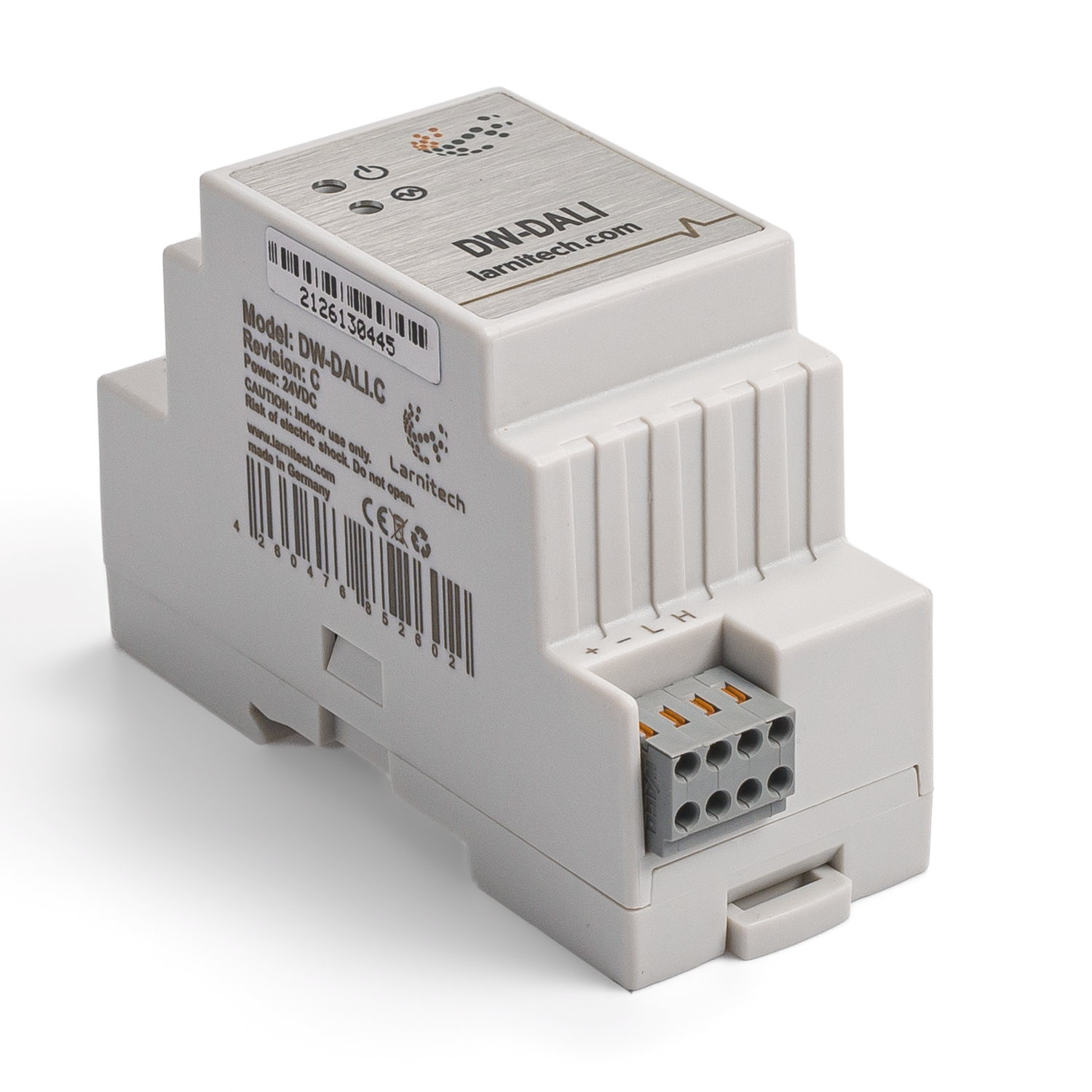
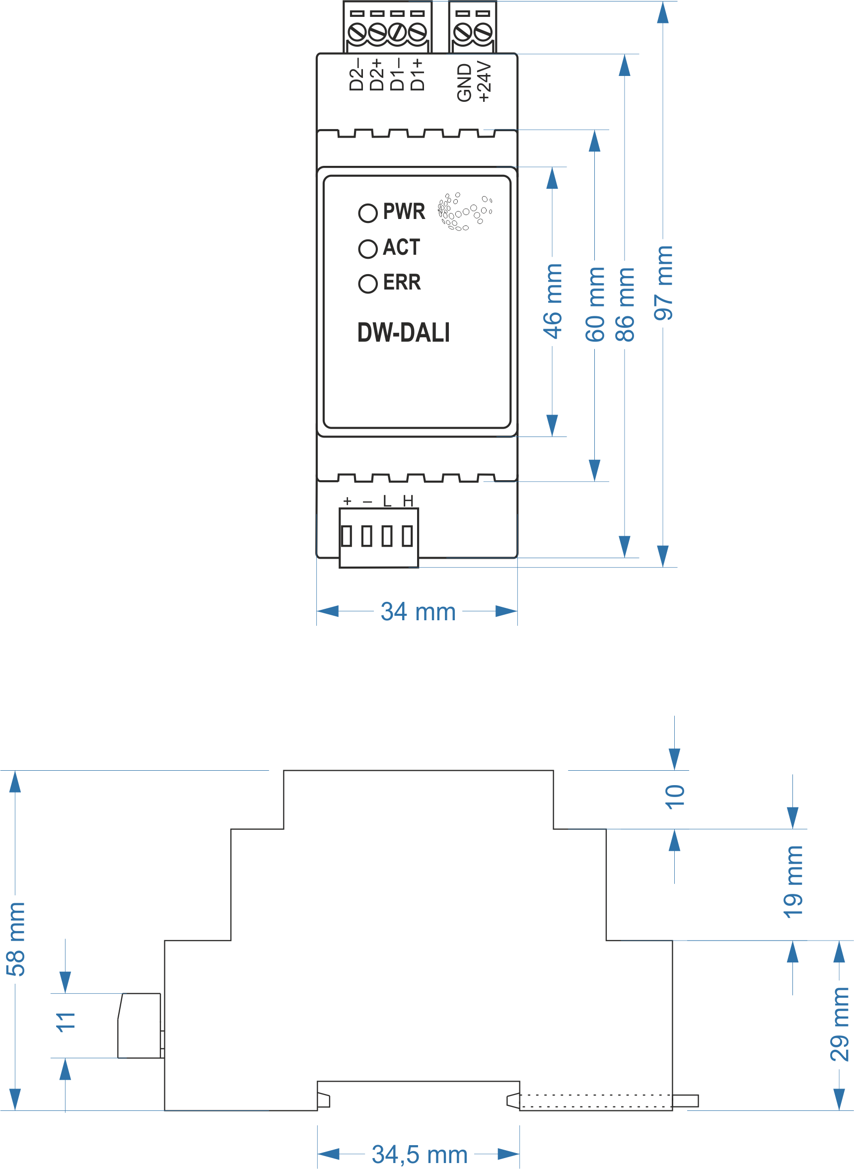
Размеры модуля
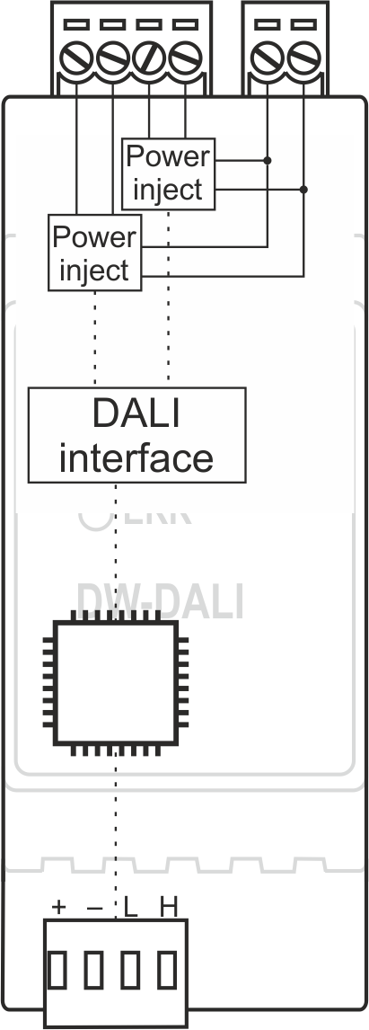
Внутренняя компоновка
Конфигурация и правильное использование модуля
Правильное использование модуля
Модуль DW-DALI.A предназначен для использования в составе проводной системы Larnitech Smart House. DW-DALI.A должен использоваться для обмена данными между устройствами, подключенными к шине CAN, и такими устройствами, как электронные балласты и диммеры, поддерживающими интерфейс DALI (Digital Addressable Lighting Interface).
Комплектность
В комплект поставки входят:
| Parameter name | Value |
|---|---|
| DALI ports qty | 2 |
| DALI-line voltage supply | 10.5 – 22.5 V DC |
| Peak current of DALI-line power supply | 1A |
| Peak current in DALI-line | 300 mА |
| Maximum DALI devices quantity | 641 |
| Power supply | 11.5 … 27.5 V DC from CAN |
| Max current(24V) | 30 mA |
| Bus type | CAN (4-wire) |
| Equipment installation type | DIN rail (EN 60715) |
| Case material | ABS |
| Protection | IP40 |
| Temperature range | -10 … +50 °C |
| Size | 2U, 35x97x58 mm |
| Weight | 75g |
Module general structure
At the bottom of the casing there is a connecting plug (3) to the CAN-bus of Smart House network.
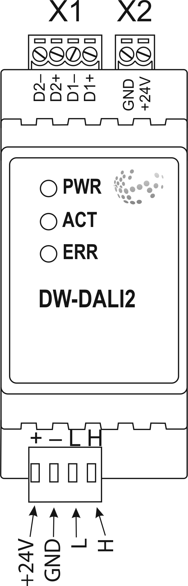
The physical configuration and contact point assignment of each connector are shown in table
| Connector | Contact | Assignment |
|---|---|---|
1 DALI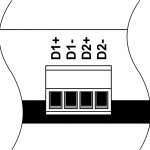 |
D1+ D1- D2+ D2- |
DALI1 bus DALI2 bus |
| 2 DALI power supply |
+24V GND |
+24V — DALI bus power supply GND — common |
| 3 Module indicating unit |
The scenario for module indicating unit is shown below | |
| 4 CAN |
VCC GND L H |
VСС — +24V power supply of CAN-bus GND — common L — CAN-L data bus H — CAN-H data bus |
| Indicator | Status | Description |
|---|---|---|
| Power | Power | |
| Power not available | ||
| Activity | Data communication | |
| Data communication not available | ||
| Error | No errors | |
| Overheating | ||
| The data has not been transferred via the CAN bus for at least 5 minutes. | ||
| No power on the DALI bus or over current (more then 180 mA) on DALI bus. If over current is at both bus blinking twice in half a second. |
Module installation and assembly
Before connecting the module, you must determine the module installation place. Note: The module must be installed near 24V power supply.
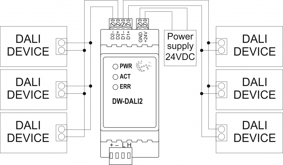
Typical diagram for DW-DALI.A module connection
Module installation and connection procedure
CAUTION! You must precisely follow the recommendations listed in the «Safety Requirements» section of this manual.
- Install the module in the switchboard on the DIN-rail and secure it with special latches available on the module base.
- Connect the CAN-bus (4).
- Connect the DALI-bus (1).
- Connect the DALI power connector (2).
- Energise the module power supply (24 V).
Module shutoff and disassembly procedure
- isconnect the power connector (2).
- Disconnect the DALI connector (1).
- Disconnect the connector of CAN-bus (4).
- Demount the module from the DIN-rail, releasing the latch, available at the module base.
Hardware setup
To configure and control DW-DALI module, you must install Larnitech software on your smartphone or t, which is available in App Store and Play Market. After installation, follow the System Setup Instructions.
Fault diagnostics and handling
The following are some possible faults and ways of fault handling. If you have any difficulty, or face the fault undeclared here, please contact the Technical Support: http://www.larnitech.com/support/ or support@larnitech.com. There are also some tips in the FAQ section at our website http://www.larnitech.com/faq/
System Setup Instruction
Each DALI bus can use 40 DALI devices. Together DALI buses for one DW-DALI.A can use 64 DALI devices. Address DALI device must be from 1 to 63. To add DALI devices to DALI bus, add «hw» to tag with SubID 98, hw=”bus1=’1,2,3,…’ bus2=’1,2,3,…’ “:
- bus1 — first DALI bus data;
- bus2 — second DALI bus data;
- 1,2,3 — address DALI devices.
Configuring DALI device settings(set from scripts):
— setStatus(ID:SID, {0xC0, ADDR}) – set address DALI devices, need to connect one DALI device on DALI bus data:
- ID:SID — address DALI bus data (com-port in logic.xml);
- 0xC0 — command for set address DALI devices;
- ADDR — address DALI device.
— setStatus(ID:SID, {0xD4, ADDR, LEVEL}) — set default brightness:
- ID:SID — address DALI bus data (com-port in logic.xml);
- 0xD4 — command for set default brightness DALI devices;
- ADDR — address DALI device;
- LEVEL — brightness level, 0…250.
— setStatus(ID:SID, {0xD3, ADDR, TIME}) — set the brightness change time:
- ID:SID — address DALI bus data (com-port in logic.xml);
- 0xD3 — command for set the brightness change time DALI devices;
- ADDR — address DALI device;
- TIME — brightness change time, in seconds.
— setStatus(ID:SID, {0xD1, ADDR, LEVEL}) — set minimum brightness:
- ID:SID — address DALI bus data (com-port in logic.xml);
- 0xD1 — command for set minimal brightness DALI devices;
- ADDR — address DALI device;
- LEVEL — brightness level, 0…250.
— setStatus(ID:SID, {0xD0, ADDR, LEVEL}) — set maximum brightness:
- ID:SID — address DALI bus data (com-port in logic.xml);
- 0xD0 — command for set maximum brightness DALI devices;
- ADDR — address DALI device;
- LEVEL — brightness level, 0…250.
HW Settings
| Name | Type, range | SUBID | Default | Description |
|---|---|---|---|---|
| def | string 'ON' | certain SubID | 'OFF' | def is the element status is set after restart (only for Scenes).
hw="def='ON'" |
| def | integer 0…250 integer -0…-250 |
certain SubID | 100 | The default brightness level in case of a power reset (0..250). Negative value will turned on the element.Example:
hw="def=250" |
| def | string 'last' | certain SubID | 'off' | Set last saved state of the element in case of a power reset. The element save his state after stay unchanged for 10 minutes.
hw="def='last'" |
| dmin | integer (0…254) | certain SubID | 0 | minimum dimming level, 0..254; only for Groups
Example: hw="dmin=30" |
| dmax | integer (0…254) | certain SubID | 250 | maximum dimming level, 0..254; only for Groups
Example: hw="dmax=80" |
 1<item addr="450:1" auto-period="600" cfgid="80" hw="min=30 max=80 hill" name="Dimmer" type="dimer-lamp" uniq_id="4138"/>
 2<item addr="450:2" auto-period="600" cfgid="80" hw="min=30 max=80 pit" name="Dimmer" type="dimer-lamp" uniq_id="4139"/>
 3<item addr="450:3" auto-period="600" cfgid="80" name="Dimmer" type="dimer-lamp" uniq_id="4140"/>
 4<item addr="450:4" auto-period="600" cfgid="80" name="Dimmer" type="dimer-lamp" uniq_id="4141"/>
 5<item addr="450:5" auto-period="600" cfgid="80" name="Dimmer" type="dimer-lamp" uniq_id="4142"/>
 6<item addr="450:6" auto-period="600" cfgid="80" name="Lamp" type="lamp" uniq_id="4143"/>
 7<item addr="450:7" auto-period="600" cfgid="80" name="Lamp" type="lamp" uniq_id="4144"/>
 8<item addr="450:8" auto-period="600" cfgid="80" name="Lamp" type="lamp" uniq_id="4145"/>
 9<item addr="450:9" auto-period="600" cfgid="80" name="Lamp" type="lamp" uniq_id="4146"/>
10<item addr="450:10" auto-period="600" cfgid="80" name="Lamp" type="lamp" uniq_id="4147"/>
11<item addr="450:11" auto-period="600" cfgid="80" name="Lamp" type="lamp" uniq_id="4148"/>
12<item addr="450:12" auto-period="600" hw="min=30" cfgid="80" name="Dimmer" type="dimer-lamp" uniq_id="4149"/>
13<item addr="450:13" auto-period="600" cfgid="80" name="Lamp" type="lamp" uniq_id="4164"/>
14<item addr="450:41" auto-period="600" hw="min=30 max=80 hill" cfgid="80" name="Dimmer" type="dimer-lamp" uniq_id="4151"/>
15<item addr="450:42" auto-period="600" hw="min=30 max=80 pit" cfgid="80" name="Dimmer" type="dimer-lamp" uniq_id="4152"/>
16<item addr="450:43" auto-period="600" cfgid="80" name="Dimmer" type="dimer-lamp" uniq_id="4153"/>
17<item addr="450:44" auto-period="600" cfgid="80" name="Dimmer" type="dimer-lamp" uniq_id="4154"/>
18<item addr="450:45" auto-period="600" cfgid="80" name="Dimmer" type="dimer-lamp" uniq_id="4155"/>
19<item addr="450:46" auto-period="600" cfgid="80" name="Lamp" type="lamp" uniq_id="4156"/>
20<item addr="450:47" auto-period="600" cfgid="80" name="Lamp" type="lamp" uniq_id="4157"/>
21<item addr="450:48" auto-period="600" cfgid="80" name="Lamp" type="lamp" uniq_id="4158"/>
22<item addr="450:49" auto-period="600" cfgid="80" name="Lamp" type="lamp" uniq_id="4159"/>
23<item addr="450:50" auto-period="600" cfgid="80" name="Lamp" type="lamp" uniq_id="4160"/>
24<item addr="450:51" auto-period="600" cfgid="80" name="Lamp" type="lamp" uniq_id="4161"/>
25<item addr="450:52" auto-period="600" hw="max=80" cfgid="80" name="Dimmer" type="dimer-lamp" uniq_id="4162"/>
26<item addr="450:53" auto-period="600" cfgid="80" name="Lamp" type="lamp" uniq_id="4165"/>
27<item addr="450:85" cfgid="80" name="RS232" type="com-port" uniq_id="4135"/>
28<item addr="450:86" cfgid="80" name="RS232" type="com-port" uniq_id="4136"/>
29<item addr="450:98" cfgid="80" hw="bus1='1-5,10L-15,20,25L' bus2='1-5,10L-15,20,25L'" name="Temperature" system="yes" type="temperature-sensor" uniq_id="4137"/>