Difference between revisions of "DW-DISPATCH/ru"
Jump to navigation
Jump to search
(Created page with "==МОДУЛЬ АВТОМАТИЧЕСКОГО СЧИТЫВАНИЯ ПОКАЗАНИЙ СЧЕТЧИКА==") |
(Created page with "Модуль предназначен только для системы диспетчеризации. Он не используется в основной системе...") |
||
| Line 18: | Line 18: | ||
==МОДУЛЬ АВТОМАТИЧЕСКОГО СЧИТЫВАНИЯ ПОКАЗАНИЙ СЧЕТЧИКА== | ==МОДУЛЬ АВТОМАТИЧЕСКОГО СЧИТЫВАНИЯ ПОКАЗАНИЙ СЧЕТЧИКА== | ||
| − | + | Модуль предназначен только для системы диспетчеризации. Он не используется в основной системе Larnitech Smart Home. | |
<div class="caution"> | <div class="caution"> | ||
Revision as of 13:19, 8 January 2022
| DW-DISPATCH | |||||||
|---|---|---|---|---|---|---|---|
 | |||||||
| |||||||
| |||||||
МОДУЛЬ АВТОМАТИЧЕСКОГО СЧИТЫВАНИЯ ПОКАЗАНИЙ СЧЕТЧИКА
Модуль предназначен только для системы диспетчеризации. Он не используется в основной системе Larnitech Smart Home.
CAUTION! All work related to the installation, connection, setting up, service and support must be carried out by qualified personnel with sufficient skills and experience in working with electrical equipment. To avoid the risk of fire, electric shock, damage to the system and/or personal injury, the system installation and assembly must be performed in accordance with the instructions listed below:
- all connectivity work must be carried out with the power turned OFF;
- use appropriate tools and personal protection against electric shock;
- do not use damaged cables, wires and connectors;
- avoid folding the cables and wires;
- do not apply excessive force to the wires by kinking or pressing them too hard: the inner conductors of the cables and wires may get stripped or damaged;
- do not use the power socket with poor contacts to connect;
- do not exceed the load limit parameters specified in the manual;
- the supply conductors wire section is subject to the specifications for current density limit, insulation type and wire material. Light section can result in cable overheating and fire.
When the power is on, NEVER:
- connect/disconnect the connectors;
- open modules and sensors.
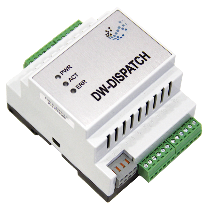
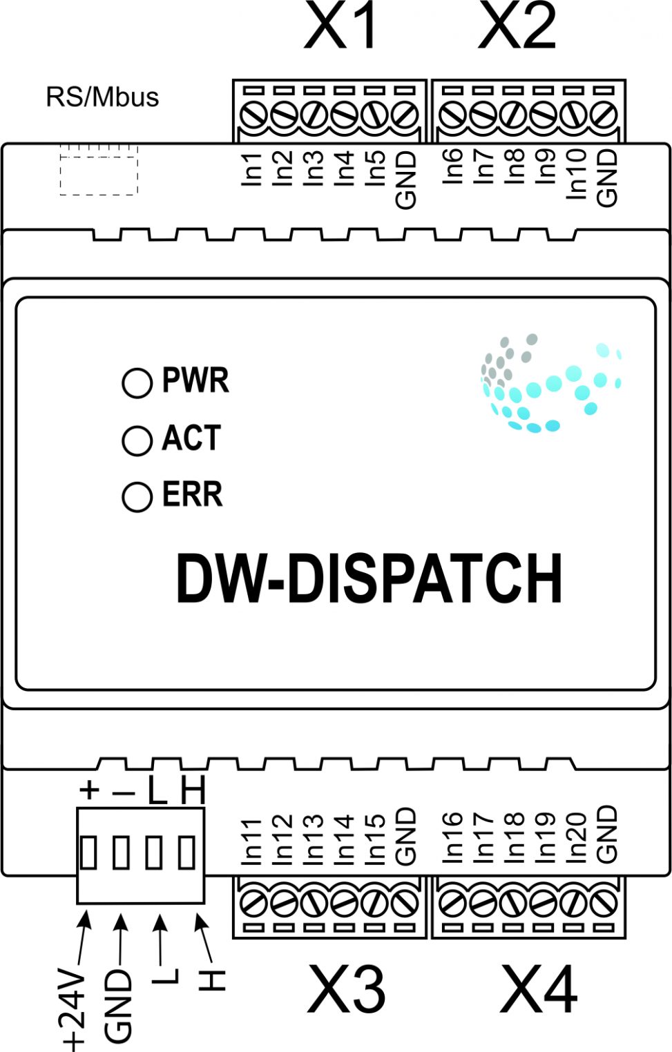
Overview
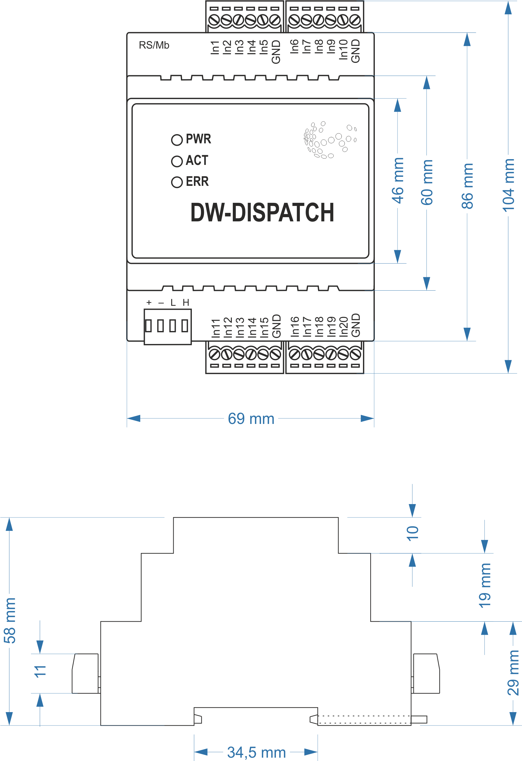
Module dimensions
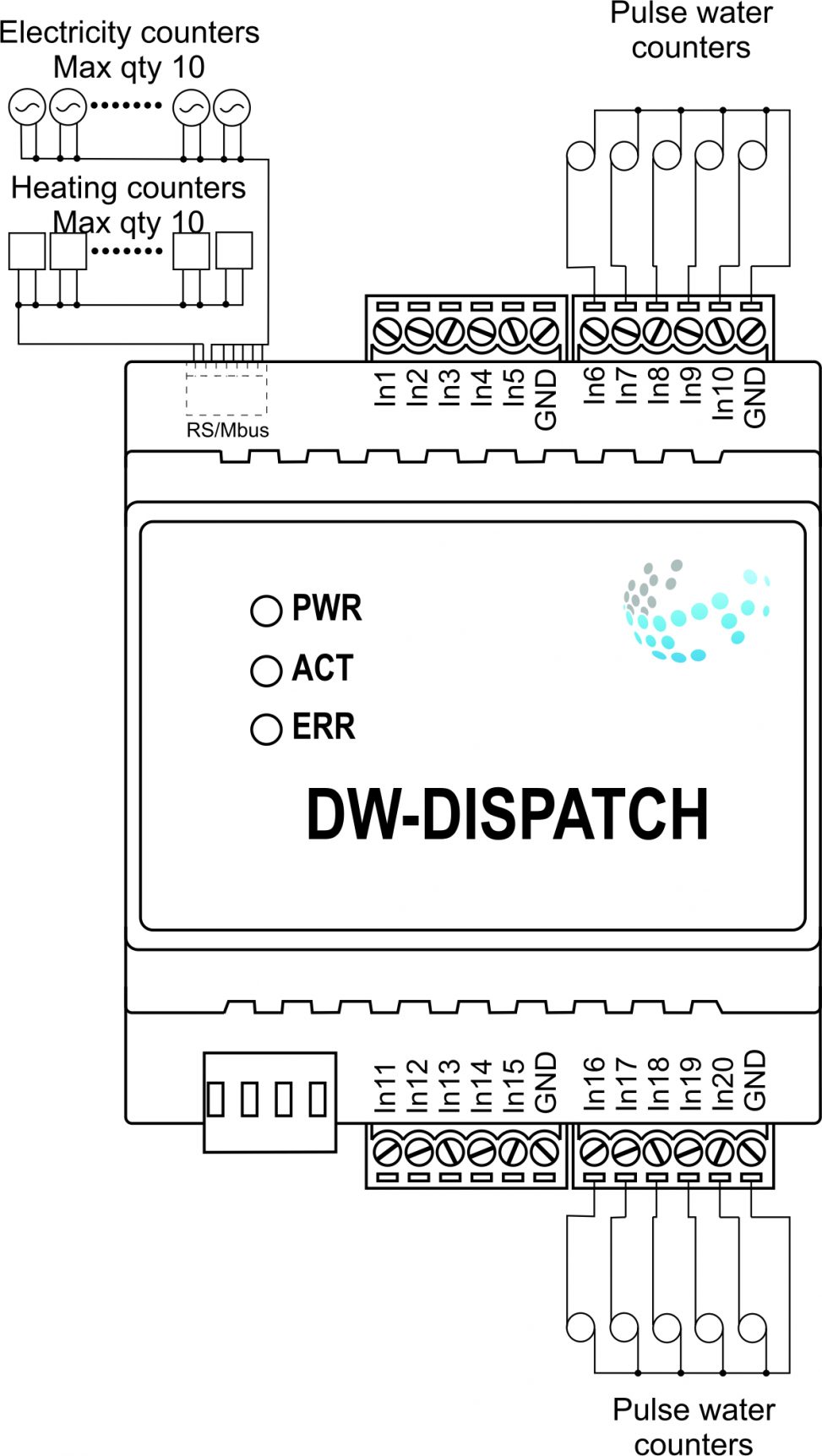
Example of connection
Module parameters
| Parameter name | Value |
|---|---|
| RS485 ports qty | 1 |
| M-BUS port quantity | 1 |
| Pulse inputs quantity | 20 |
| Power supply | 11.5 … 27.5 V DC from CAN |
| Max current(24V) | 45 mA |
| Push-button/reed switches line recommended length | 300m |
| Bus type | CAN (4-wire) |
| Equipment installation type | DIN rail (EN 60715) |
| Case material | ABS |
| Protection | IP40 |
| Temperature range | -10 … +50 °C |
| Size | 4U, 69x104x58 mm |
| Weight | 130g |
Indication of module operation
| Indicator | Status | Description |
|---|---|---|
| Power | Power | |
| Power not available | ||
| Activity | Data communication | |
| Data communication not available | ||
| Error | No errors | |
| Overheating | ||
| The data has not been transferred via the CAN bus for at least 5 minutes. |
Module installation and connection procedure
- Install the module in the switchboard on the DIN rail and fix it with the special latch on the module base.
- Connect the X1-X4 connectors.
- Connect the CAN connector.
- Configure the module using LT setup.
- Check all equipment for proper operation.
Module shut-off and deinstallation procedure
- Disconnect the CAN connector.
- Disconnect the X1-X4 connectors.
- Remove the module from the DIN rail, releasing the latch at the bottom of the module base.