DW-DM02
| DW-DM02.С | |||||||||
|---|---|---|---|---|---|---|---|---|---|
 | |||||||||
| |||||||||
2-CHANNEL DIMMER
This module is designed for smooth adjustment of brightness of lighting devices (non reactive load). The dimmer type is MOSFET with trailing edge dimming. Like all Larnitech devices, this dimmer controller is automatically detected and configured when it is added to the system. A logical unit within makes it possible for the unit to perform scripts from Larnitech’s large and constantly updated database and to operate on distributed logic, ensuring the reliability of its operation. Advanced LED light settings allow a more precise setup, while soft start mode prolongs lamp life. In addition to featuring protection in a range of parameters.
Features
- R/C load type has 2 channels. Each channel supports up to 300 W
- Works with halogen /LED lights
- Advanced LED light settings
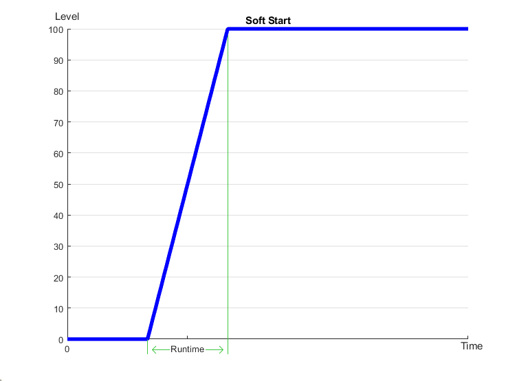
- Soft start mode
- Overload protection
- Overheating protection
- Short-circuit protection
- Plug and play (automatically detected and configured by the system)
- In-built logical unit
- Regular system updates
CAUTION! All work related to the installation, connection, setting up, service and support must be carried out by qualified personnel with sufficient skills and experience in working with electrical equipment. To avoid the risk of fire, electric shock, damage to the system and/or personal injury, the system installation and assembly must be performed in accordance with the instructions listed below:
- all connectivity work must be carried out with the power turned OFF;
- use appropriate tools and personal protection against electric shock;
- do not use damaged cables, wires and connectors;
- avoid folding the cables and wires;
- do not apply excessive force to the wires by kinking or pressing them too hard: the inner conductors of the cables and wires may get stripped or damaged;
- do not use the power socket with poor contacts to connect;
- do not exceed the load limit parameters specified in the manual;
- the supply conductors wire section is subject to the specifications for current density limit, insulation type and wire material. Light section can result in cable overheating and fire.
When the power is on, NEVER:
- connect/disconnect the connectors;
- open modules and sensors.
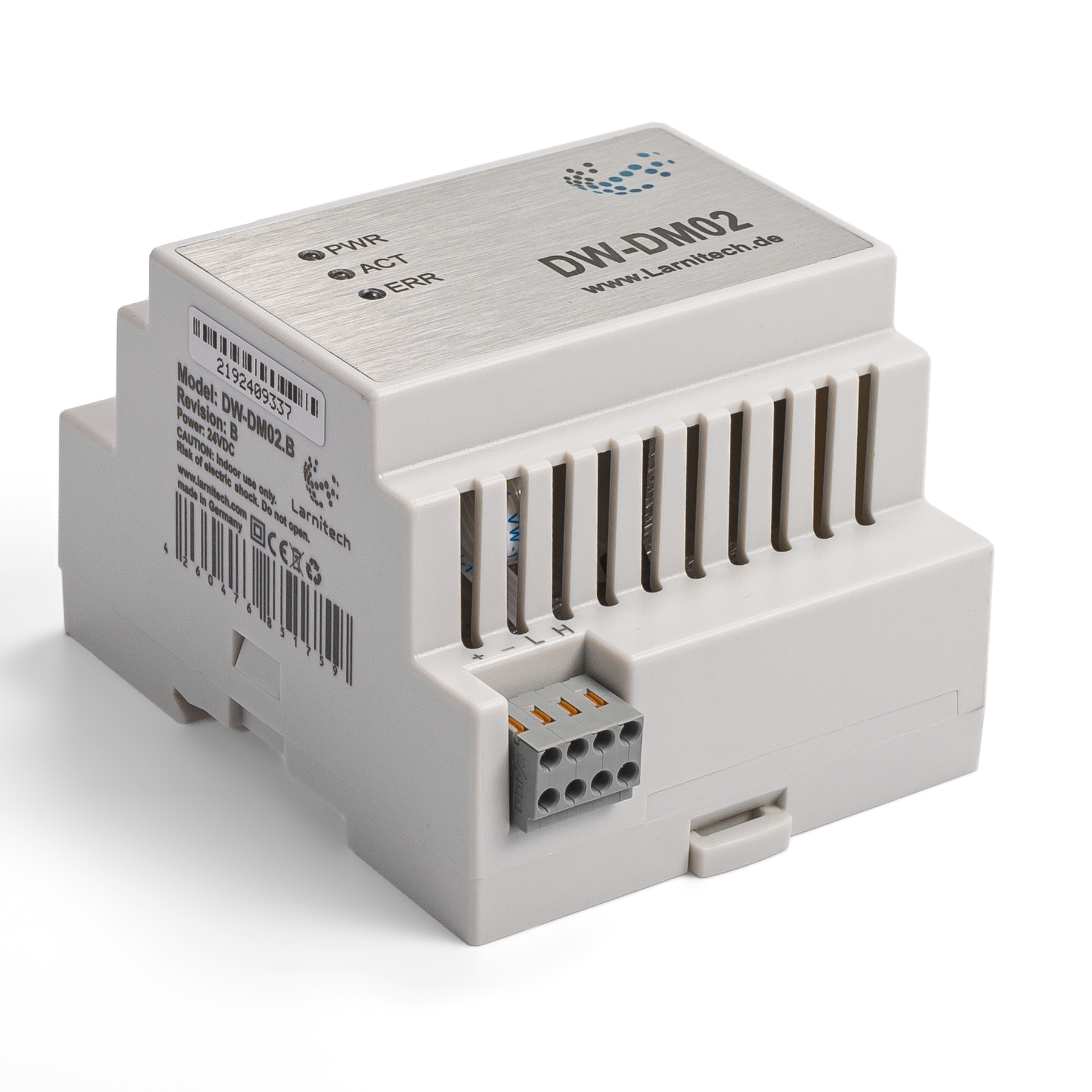
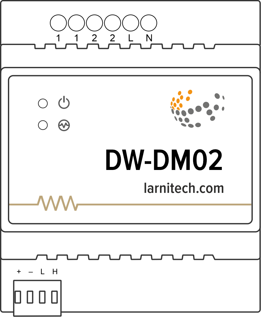
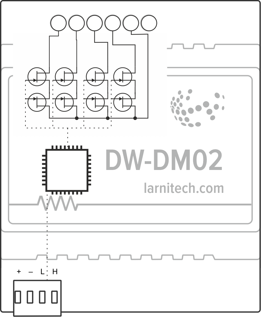
Overview
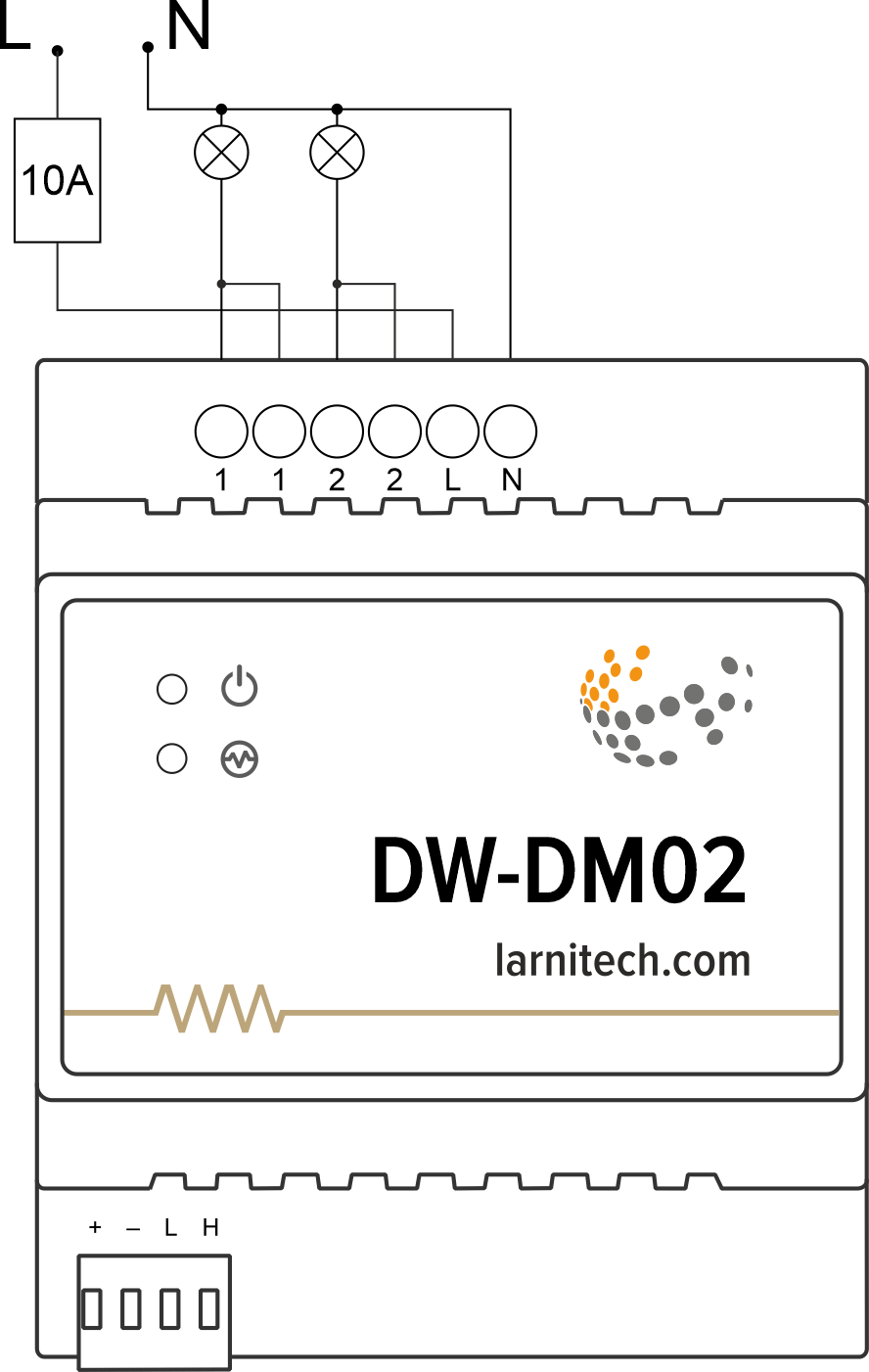
Example of connection
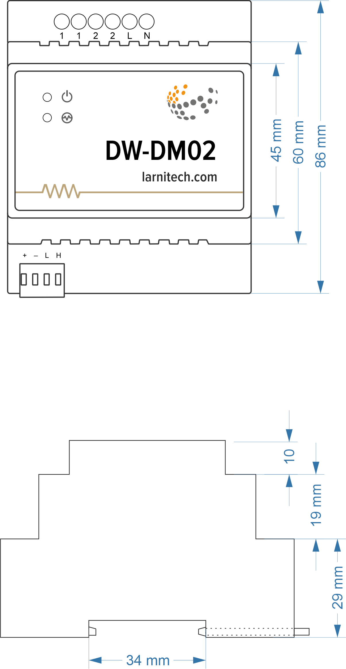
Module dimensions
Internal layout
Module parameters
| Parameter name | Value |
|---|---|
| Dimming channels qty | 2 |
| Input voltage | 100-240V AC, 50-60 Hz |
| Current type | AC |
| Max load per channel | 4.54A (1000W at 220V) |
| Max load per device | 7.27A (1600W at 220V) |
| Dimmer type | MOSFET |
| Dimming type | trailing edge |
| Power supply | 11.5 … 27.5 V DC from CAN |
| Max current(24V) | 35 mA |
| Bus type | CAN (4-wire) |
| Equipment installation type | DIN rail (EN 60715) |
| Case material | ABS |
| Protection | IP40 |
| Temperature range | -10 … +50 °C |
| Size | 4U, 69x102x58 mm |
| Weight | 180g |
Supported load types
| Supported load type | Power | |
|---|---|---|
 |
Conventional incandescent lamps | 0-1000W |
 |
Halogen light sources | 0-1000W |
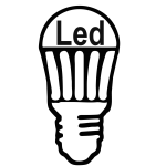 |
LED lamps with dimming support | 0-1000W |
 |
Energy saving lamps with dimming support | 0-1000W |
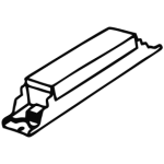 |
Electronic ballasts with dimming support | 0-1000W |
Indication of module operation
Bootloader
| Indicator | Status | Description |
|---|---|---|
| Device in bootloader | ||
| Waiting for bootloader command | ||
| Flashing firmware |
Firmware
| Indicator | Status | Description |
|---|---|---|
| Identification | ||
| Operational mode | ||
Error | ||
| Lost connection to server | ||
| Overheat | ||
| No AC power | ||
| RTC error |
Module installation and connection procedure
- Install the module in the switchboard on the DIN rail and fix it with the special latch on the module base.
- Connect the CAN connector.
- Connect the contacts (1-2).
- Configure the module using LT setup.
- Apply power to the load.
- Check all equipment for proper operation.
Module shut-off and deinstallation procedure
- Disconnect the power from the load.
- Disconnect the contacts (1-2).
- Disconnect the CAN connector.
- Remove the module from the DIN rail, releasing the latch at the bottom of the module base.
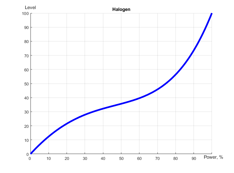
Dimmer workflow
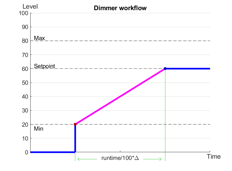
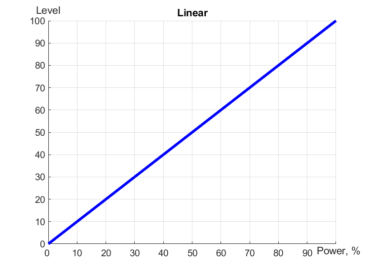
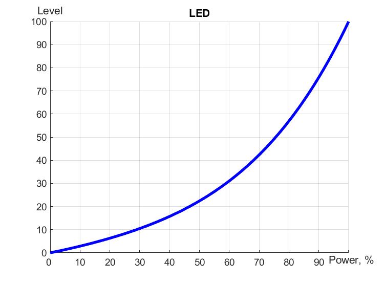
Linear, LED and Halogen workflows
HW settings
| Name | Type, range | SUBID | Default | Description |
|---|---|---|---|---|
| dm | char[2] | 98 | 'LL' | Each char is responsible for the type of a particular channel
Example: dm='sk' |
| def | integer 0-250 | 1-2 | 100 | The default brightness level in case of a power reset (1..250). Example: def=250 |
| min | integer 0-100 | 1-2 | 0 | Minimum dimming level, example: min=10 |
| max | integer 0-100 | 1-2 | 100 | Maximum dimming level, example max=95 |
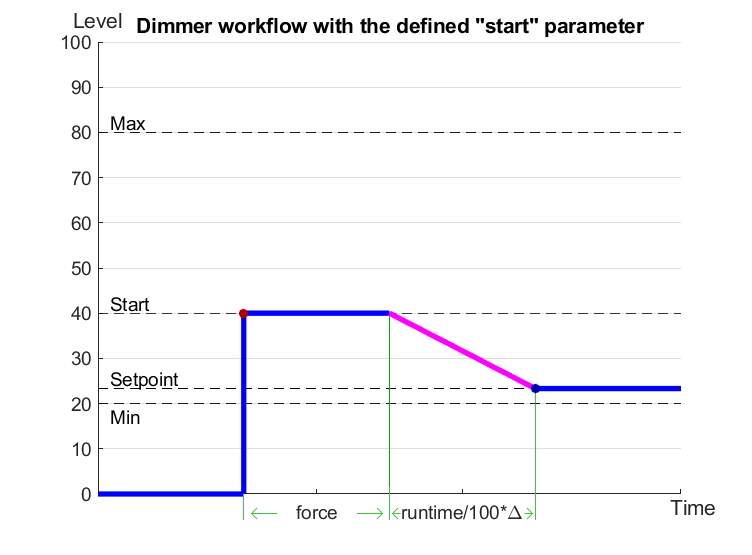
| start | integer 0-100 | 1-2 | 0 | The Start function is used for lamps that lack the minimal voltage to get turned on. If the set value is lower than the start value, the lamp is turned on at the start value and them the light is dimmed down to the set level. Example: start=60 |
| force | integer 0-100 | 1-2 | 10 | Time duration of the starting value (measured in milliseconds). Example: force=20 |
| runtime | integer 0-60000 | 1-2 | 1000 | Runtime is the speed of changing the brightness from 'min' to 'max' (measured in milliseconds). Example: runtime=1000 |
1<item addr="307:1" auto-period="600" cfgid="77" hw="def=200 min=30 max=88 start=35 force=20 runtime=1000 " name="Dimmer" type="dimer-lamp" uniq_id="51"/>
2<item addr="307:2" auto-period="600" cfgid="77" hw="min=20 max=90 " name="Dimmer" type="dimer-lamp" uniq_id="52"/>
3<item addr="307:3" auto-period="600" cfgid="77"  name="Dimmer" type="dimer-lamp" uniq_id="53"/>
4<item addr="307:97" cfgid="77" name="Temperature" system="yes" type="temperature-sensor" uniq_id="55"/>
5<item addr="307:98" cfgid="77" hw="dm='+-'" name="Temperature" system="yes" type="temperature-sensor" uniq_id="56"/>