DW-HC08.A
Jump to navigation
Jump to search
| DW-HC08.A | |||||||
|---|---|---|---|---|---|---|---|
 | |||||||
| |||||||
| |||||||
8-МИ КАНАЛЬНЫЙ КОНТРОЛЛЕР ОТОПЛЕНИЯ
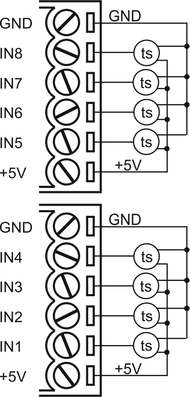
Устройство предназначено для управления отопительными приборами (радиаторами, теплыми полами, фанкойлами и т. д.). Устройство оснащено 8-ю входными каналами для подключения датчиков температуры (FW-FT или FW-TS).
Функции
- 8 выходов для клапанов или контакторов NO/NC
- 8 входов для цифровых датчиков температуры (FW-FT или FW-TS)
- Можно использовать данные о температуре из других модулей
- 8 независимых зон нагрева с недельным графиком
- До 20 отопительных профилей
- Встроенные часы реального времени
ВНИМАНИЕ! Все работы, связанные с установкой, подключением, настройкой, обслуживанием и поддержкой оборудования, должны выполняться только квалифицированным персоналом, обладающим достаточными навыками и опытом работы с электрооборудованием! Во избежание риска возгорания, поражения электрическим током, повреждения системы и/или травм, установка и сборка системы должны выполняться в соответствии с указаниями, перечисленными ниже:
- все работы по подключению должны выполняться при выключенном питании;
- необходимо использовать соответствующие инструменты и средства индивидуальной защиты от поражения электрическим током;
- запрещается использовать поврежденные кабели, провода и разъемы;
- избегайте перегиба проводов и кабелей;
- не прилагайте чрезмерных усилий к проводам путем их перегиба или слишком сильного сжатия: внутренние проводники кабелей и проводов могут быть оголены или повреждены;
- не используйте для подключения разъемы с плохими контактами;
- не превышайте параметры предельной нагрузки, указанные в инструкции;
- сечение питающих проводов зависит от требований к пределу плотности тока, типу изоляции и материалу проводов. Недостаточное сечение провода может привести к перегреву кабеля и возгоранию.
Когда питание включено, НИКОГДА:
- не подключайте/отключайте разъемы;
- не открывайте модули и датчики.
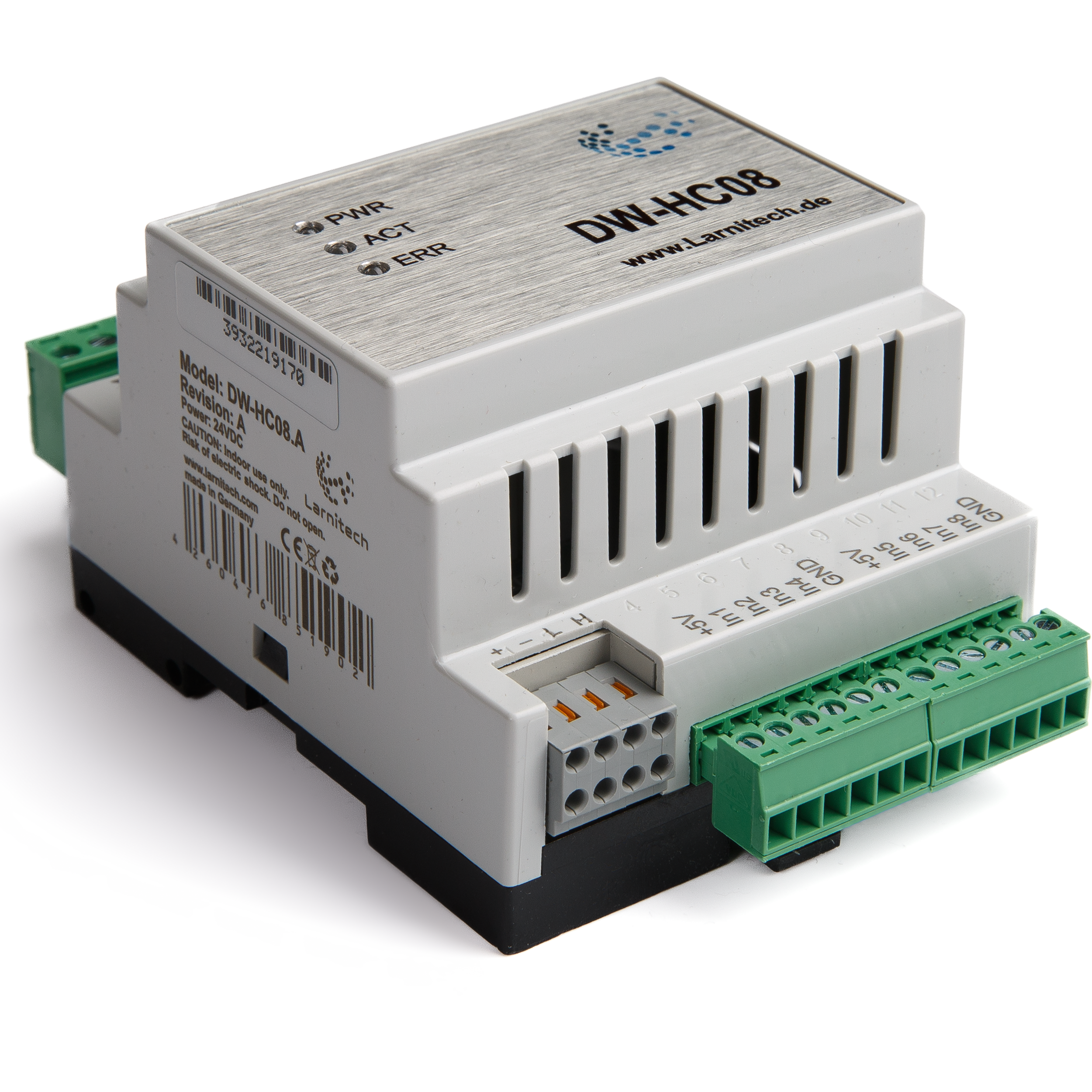
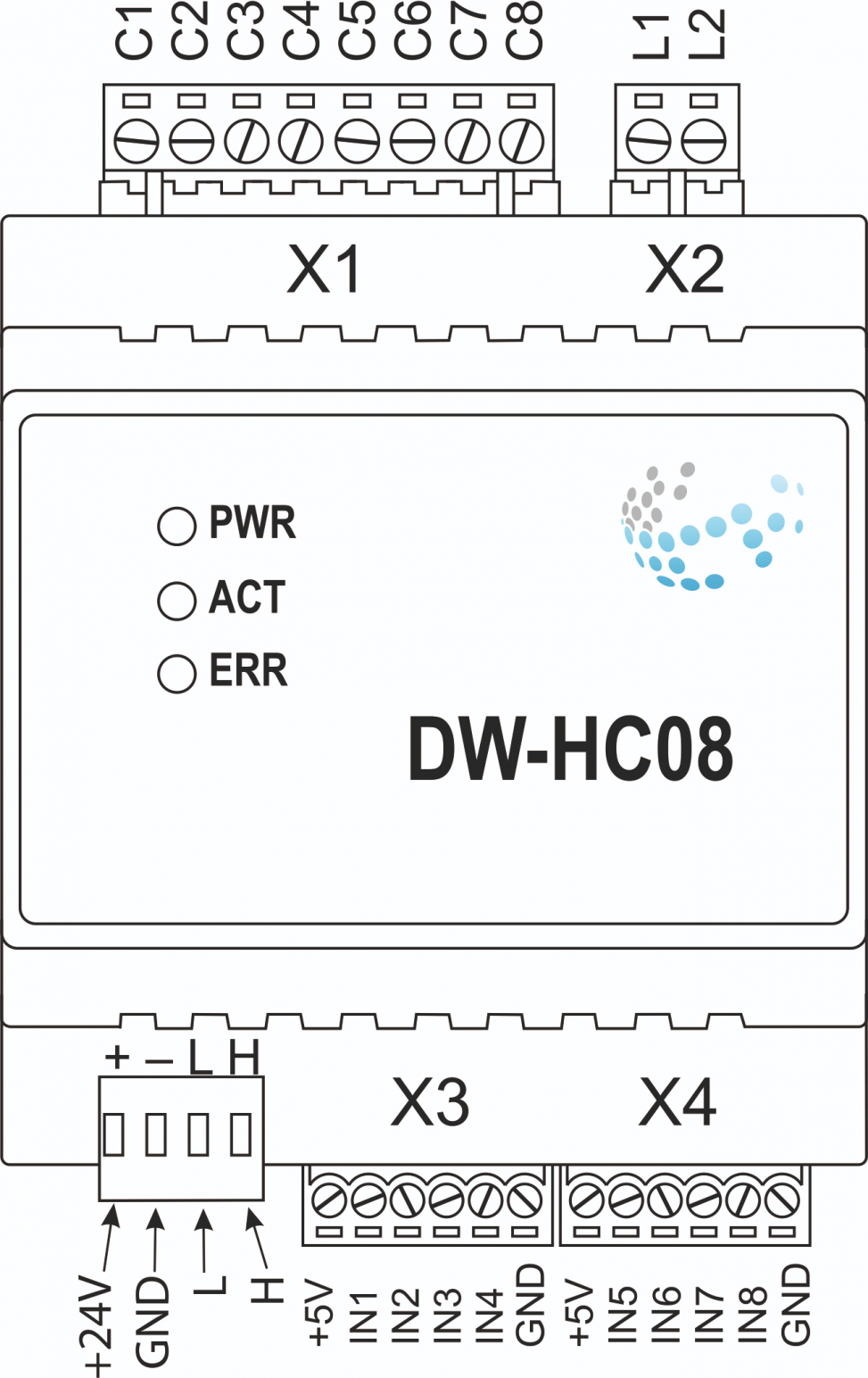
Изображение модуля
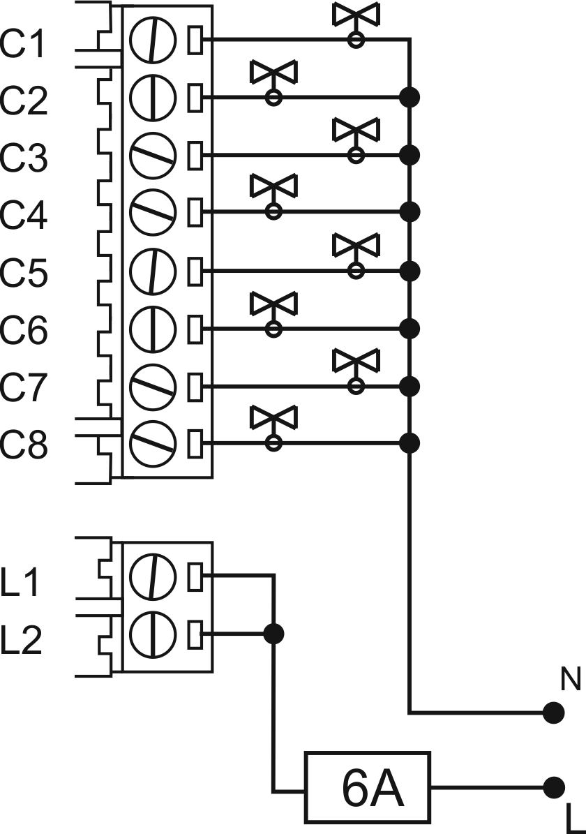
Подключение 8-ми клапанов
Подключение 8-ми датчиков температуры
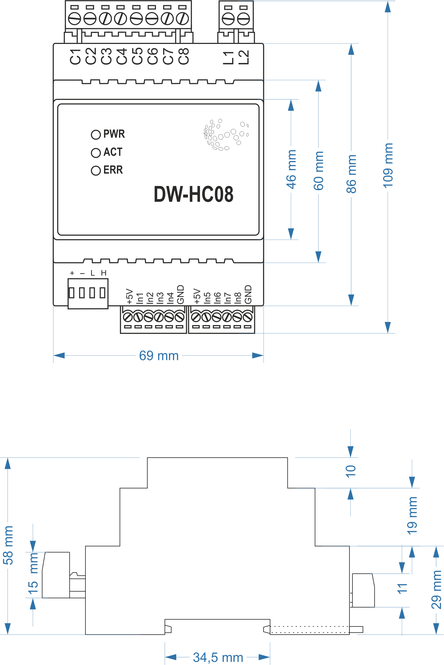
Размеры модуля
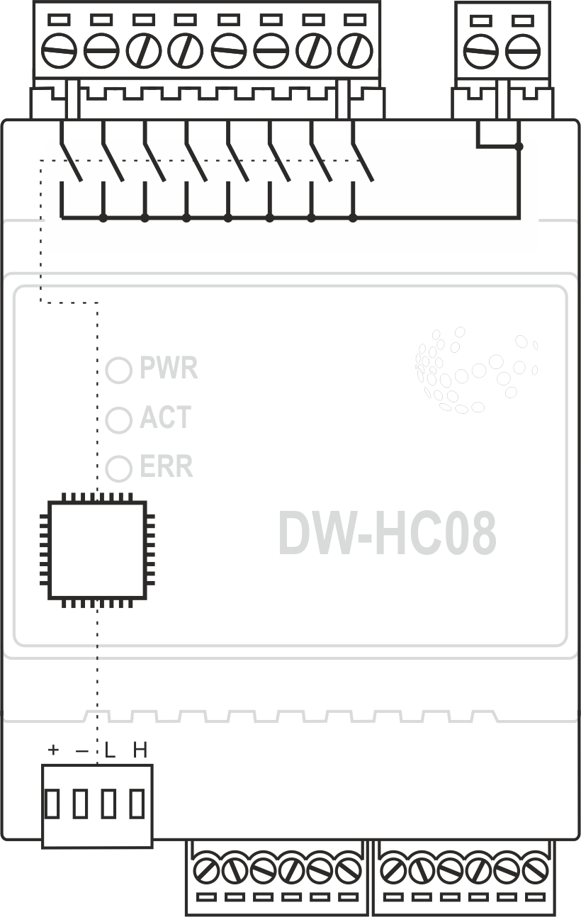
Внутренняя компоновка
Module parameters
| Parameter name | Value |
|---|---|
| Input channels qty | 8 |
| Output channels qty | 8 |
| Input voltage | 20-250V |
| Current type | AC/DC |
| Max load per channel | 0.5A(110W at 220V) |
| Power supply | 11.5 … 27.5 V DC from CAN |
| Max current(24V) | 90 mA |
| Sensors line max length | 30m |
| Bus type | CAN (4-wire) |
| Equipment installation type | DIN rail (EN 60715) |
| Case material | ABS |
| Protection | IP40 |
| Temperature range | -10 … +50 °C |
| Size | 4U, 69x110x58 mm |
| Weight | 140 g |
Connection of high load device
 |
Recomended contactors:
|
Indication of module operation
| Indicator | Status | Description |
|---|---|---|
| Power | Power | |
| Power not available | ||
| Activity | Data communication | |
| Data communication not available | ||
| Error | No errors | |
| Overheating | ||
| The data has not been transferred via the CAN bus for at least 5 minutes. |
Module installation and connection procedure
- Install the module in the switchboard on the DIN rail and fix it with the special latch on the module base.
- Connect the CAN connector.
- Connect the X1-X3 connectors.
- Configure the module using LT setup.
- Apply power to the load.
- Check all equipment for proper operation.
Module shut-off and deinstallation procedure
- Disconnect the power from the load.
- Disconnect the X1-X3 connectors.
- Disconnect the CAN connector.
- Remove the module from the DIN rail, releasing the latch at the bottom of the module base.
HW settings
| Name | Type, range | SUBID | Default | Description |
|---|---|---|---|---|
| runtime | integer 0-100 | 1-8 | 15 | runtime is the open/close time in seconds, is used for jalousie, gate, valve(2 pole); Example: runtime=15 |
| hold | integer 0-10000 | 1-8 | 500 | hold is the bridging time in miliseconds, is used for gate and jalousie (by default hold is the same as runtime), lock; Example: hold=3500 |
| def | string 'ON' | 1-8 | 'OFF' | Def is the element status is set after restart, is used for lamp, heating, valve(1 pole); Example: def='ON' |
| offset | integer -39 – 39 | 31-38 | 0 | It is the sensor values offset; Example: offset='-15' |
| stop | Char 'R' | 1-7 | – | (for 2-pole gate and blinds) If it is declared then by Stop command during the motion, the same impulse appears as it was at the beginning of the motion. Pole, an which the stop-impules is formed, is defined by the parameter Stop value. If it is 'r' or 'R' then stop-impulse is produced on the opposite to the start-impulse pole. If any other value is delcared (e.g., 'd' ) then the stop-impulse is on the same pole. If a Runtime passed after the beginning of the motion then the stop-impulse is not formed. Example: stop='r' |
| out | char[8] | 98 | 'HHHHHHHH' | Each char is responsible for the type of a particular channel
Example: dm='BGLKMX' |
 1<item addr="348:1" cfgid="43" name="Jalousie" sub-type="120" type="jalousie" uniq_id="4097" hw="runtime=45"/>
 2<item addr="348:3" auto-period="600" cfgid="43" name="Lamp" type="lamp" uniq_id="4098" hw="def='ON'"/>
 3<item addr="348:4" cfgid="43" name="Gate" sub-type="120" type="gate" uniq_id="4099" hw="runtime=30"/>
 4<item addr="348:6" cfgid="43" name="Lock" type="lamp" uniq_id="4100" hw="hold=5000"/>
 5<item addr="348:7" cfgid="43" name="Radiator" type="valve-heating" uniq_id="4029" hw="def='ON'">
 6    <automation name="Eco" temperature-level="16" uniq_id="4030"/>
 7    <automation name="Comfort" temperature-level="22" uniq_id="4031"/>
 8    <automation name="Hot" temperature-level="25" uniq_id="4032"/>
 9</item>
10<item addr="348:8" cfgid="43" name="Radiator" type="valve-heating" uniq_id="4033" hw="def='OFF'">
11    <automation name="Eco" temperature-level="16" uniq_id="4034"/>
12    <automation name="Comfort" temperature-level="22" uniq_id="4035"/>
13    <automation name="Hot" temperature-level="25" uniq_id="4036"/>
14</item>
15<item addr="348:31" cfgid="43" name="Temperature" type="temperature-sensor" uniq_id="4089" hw="offset=10"/>
16<item addr="348:32" cfgid="43" name="Temperature" type="temperature-sensor" uniq_id="4090" hw="offset=-15"/>
17<item addr="348:33" cfgid="43" name="Temperature" type="temperature-sensor" uniq_id="4091"/>
18<item addr="348:34" cfgid="43" name="Temperature" type="temperature-sensor" uniq_id="4092" hw="offset=5"/>
19<item addr="348:35" cfgid="43" name="Temperature" type="temperature-sensor" uniq_id="4093"/>
20<item addr="348:36" cfgid="43" name="Temperature" type="temperature-sensor" uniq_id="4094"/>
21<item addr="348:37" cfgid="43" name="Temperature" type="temperature-sensor" uniq_id="4095"/>
22<item addr="348:38" cfgid="43" name="Temperature" type="temperature-sensor" uniq_id="4096"/>
23<item addr="348:97" cfgid="43" name="Temperature" system="yes" type="temperature-sensor" uniq_id="4041"/>
24<item addr="348:98" cfgid="43" hw="out='B-LG-KHJ'" name="Temperature" system="yes" type="temperature-sensor" uniq_id="4042"/>