Difference between revisions of "DW-HC10"
| (3 intermediate revisions by 2 users not shown) | |||
| Line 1: | Line 1: | ||
| + | <languages/> | ||
| + | <translate> | ||
| + | <!--T:1--> | ||
{{RevisionChanger | hasA = 1 | hasB = 1 | hasC = 1}} | {{RevisionChanger | hasA = 1 | hasB = 1 | hasC = 1}} | ||
{{Infobox module | {{Infobox module | ||
| Line 14: | Line 17: | ||
}} | }} | ||
| − | ==10-CHANNEL HEATING CONTROLLER== | + | ==10-CHANNEL HEATING CONTROLLER== <!--T:2--> |
| + | <!--T:3--> | ||
The device is designed for controlling heating devices (radiators, floor heating, fan coil units, etc.). | The device is designed for controlling heating devices (radiators, floor heating, fan coil units, etc.). | ||
The device is equipped with 12 input channels for connection of temperature sensors (FW-FT or FW-TS). | The device is equipped with 12 input channels for connection of temperature sensors (FW-FT or FW-TS). | ||
| − | ==Features== | + | ==Features== <!--T:4--> |
| − | *10 outputs for NO/NC valves | + | *10 outputs for NO/NC/PWM valves |
| − | |||
*12 inputs for digital/analogue temperature sensors (FW-FT, FW-TS, NTC) | *12 inputs for digital/analogue temperature sensors (FW-FT, FW-TS, NTC) | ||
*Can to use temperature data from other modules | *Can to use temperature data from other modules | ||
| Line 28: | Line 31: | ||
*Built-in real time clock | *Built-in real time clock | ||
| + | <!--T:5--> | ||
<div class="caution"> | <div class="caution"> | ||
CAUTION! All work related to the installation, connection, setting up, service and support must be carried out by qualified personnel with sufficient skills and experience in working with electrical equipment. | CAUTION! All work related to the installation, connection, setting up, service and support must be carried out by qualified personnel with sufficient skills and experience in working with electrical equipment. | ||
| Line 44: | Line 48: | ||
</div> | </div> | ||
| − | ==Overview== | + | ==Overview== <!--T:6--> |
| + | <!--T:7--> | ||
[[File:HC10C VIEW.png|500px]] | [[File:HC10C VIEW.png|500px]] | ||
| − | ==Example of connection== | + | ==Example of connection== <!--T:8--> |
| + | <!--T:9--> | ||
[[File:HC10C EXA.png|500px]] | [[File:HC10C EXA.png|500px]] | ||
| − | ==Module dimensions== | + | ==Module dimensions== <!--T:10--> |
| + | <!--T:11--> | ||
[[File:HC10C DIM.png|500px]] | [[File:HC10C DIM.png|500px]] | ||
| − | ==Module parameters== | + | ==Module parameters== <!--T:12--> |
| + | <!--T:13--> | ||
{{Mp | {{Mp | ||
| outqty = 10 | | outqty = 10 | ||
| Line 79: | Line 87: | ||
}} | }} | ||
| − | ==Connection of high load device== | + | ==Connection of high load device== <!--T:14--> |
| + | <!--T:15--> | ||
{| class="wikitable" style="width:800px" ; | {| class="wikitable" style="width:800px" ; | ||
|- | |- | ||
| Line 89: | Line 98: | ||
|} | |} | ||
| − | ==Input connector pinout== | + | ==Input connector pinout== <!--T:16--> |
| + | <!--T:17--> | ||
[[File:inputs.png|200px|Contactor]] | [[File:inputs.png|200px|Contactor]] | ||
| − | ==Example of sensors connection== | + | ==Example of sensors connection== <!--T:18--> |
| + | <!--T:19--> | ||
[[File:HC10Cexa3.png|200px|Contactor]] | [[File:HC10Cexa3.png|200px|Contactor]] | ||
| − | ==Indication of module operation== | + | ==Indication of module operation== <!--T:20--> |
===Bootloader=== | ===Bootloader=== | ||
{{indication| textBBB= Waiting for bootloader command}} | {{indication| textBBB= Waiting for bootloader command}} | ||
| Line 111: | Line 122: | ||
}} | }} | ||
| − | ==Module installation and connection procedure== | + | ==Module installation and connection procedure== <!--T:21--> |
| + | <!--T:22--> | ||
*Install the module in the switchboard on the DIN rail and fix it with the special latch on the module base. | *Install the module in the switchboard on the DIN rail and fix it with the special latch on the module base. | ||
*Connect the CAN connector. | *Connect the CAN connector. | ||
| Line 120: | Line 132: | ||
*Check all equipment for proper operation. | *Check all equipment for proper operation. | ||
| − | ==Module shut-off and deinstallation procedure== | + | ==Module shut-off and deinstallation procedure== <!--T:23--> |
| + | <!--T:24--> | ||
*Disconnect the power from the load. | *Disconnect the power from the load. | ||
*Disconnect the input/output channels. | *Disconnect the input/output channels. | ||
| Line 127: | Line 140: | ||
*Remove the module from the DIN rail, releasing the latch at the bottom of the module base. | *Remove the module from the DIN rail, releasing the latch at the bottom of the module base. | ||
| − | ==HW settings== | + | ==HW settings== <!--T:25--> |
{| class="wikitable" | {| class="wikitable" | ||
|- | |- | ||
| Line 147: | Line 160: | ||
|out||char[10]||98||'HHHHHHHHHH'||Each char is responsible for the type of a particular channel | |out||char[10]||98||'HHHHHHHHHH'||Each char is responsible for the type of a particular channel | ||
*'D'- PWM output (frequency 0.4Hz); | *'D'- PWM output (frequency 0.4Hz); | ||
| + | *'С'- Fancoil dimmer; | ||
*'L'-Lamp; | *'L'-Lamp; | ||
*'M'-Lamp Inverse; | *'M'-Lamp Inverse; | ||
| Line 176: | Line 190: | ||
|} | |} | ||
| + | <!--T:26--> | ||
<syntaxhighlight lang="xml" line=""> | <syntaxhighlight lang="xml" line=""> | ||
<item addr="348:1" cfgid="43" name="Jalousie" sub-type="120" type="jalousie" uniq_id="4097" hw="runtime=45"/> | <item addr="348:1" cfgid="43" name="Jalousie" sub-type="120" type="jalousie" uniq_id="4097" hw="runtime=45"/> | ||
| Line 204: | Line 219: | ||
<item addr="348:98" cfgid="43" hw="out='B-LG-KHJ--'" name="Temperature" system="yes" type="temperature-sensor" uniq_id="4042"/> | <item addr="348:98" cfgid="43" hw="out='B-LG-KHJ--'" name="Temperature" system="yes" type="temperature-sensor" uniq_id="4042"/> | ||
</syntaxhighlight> | </syntaxhighlight> | ||
| + | </translate> | ||
Latest revision as of 09:23, 14 February 2022
| DW-HC10.C | |||||||
|---|---|---|---|---|---|---|---|
 | |||||||
| |||||||
| |||||||
10-CHANNEL HEATING CONTROLLER
The device is designed for controlling heating devices (radiators, floor heating, fan coil units, etc.). The device is equipped with 12 input channels for connection of temperature sensors (FW-FT or FW-TS).
Features
- 10 outputs for NO/NC/PWM valves
- 12 inputs for digital/analogue temperature sensors (FW-FT, FW-TS, NTC)
- Can to use temperature data from other modules
- 10 independed heating zones with weekly shedule
- Up to 20 heating profiles
- Built-in real time clock
CAUTION! All work related to the installation, connection, setting up, service and support must be carried out by qualified personnel with sufficient skills and experience in working with electrical equipment. To avoid the risk of fire, electric shock, damage to the system and/or personal injury, the system installation and assembly must be performed in accordance with the instructions listed below:
- all connectivity work must be carried out with the power turned OFF;
- use appropriate tools and personal protection against electric shock;
- do not use damaged cables, wires and connectors;
- avoid folding the cables and wires;
- do not apply excessive force to the wires by kinking or pressing them too hard: the inner conductors of the cables and wires may get stripped or damaged;
- do not use the power socket with poor contacts to connect;
- do not exceed the load limit parameters specified in the manual;
- the supply conductors wire section is subject to the specifications for current density limit, insulation type and wire material. Light section can result in cable overheating and fire.
When the power is on, NEVER:
- connect/disconnect the connectors;
- open modules and sensors.
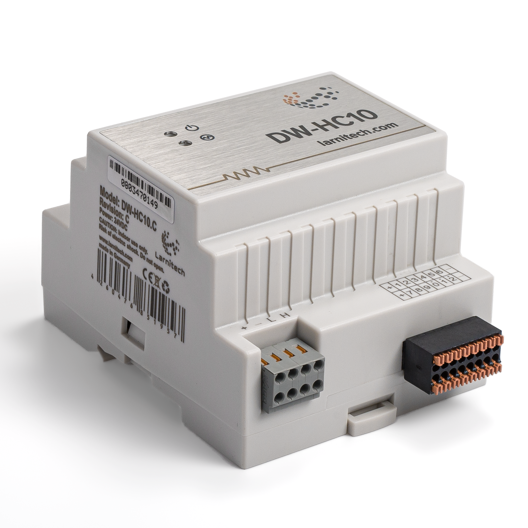
Overview
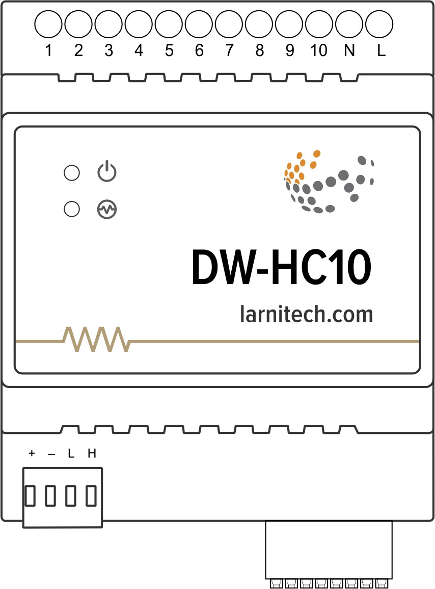
Example of connection
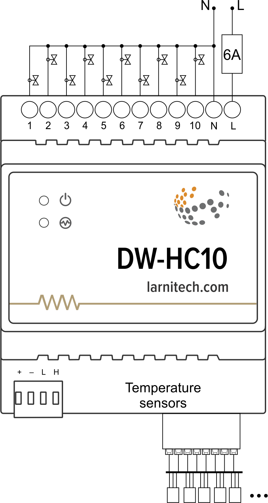
Module dimensions
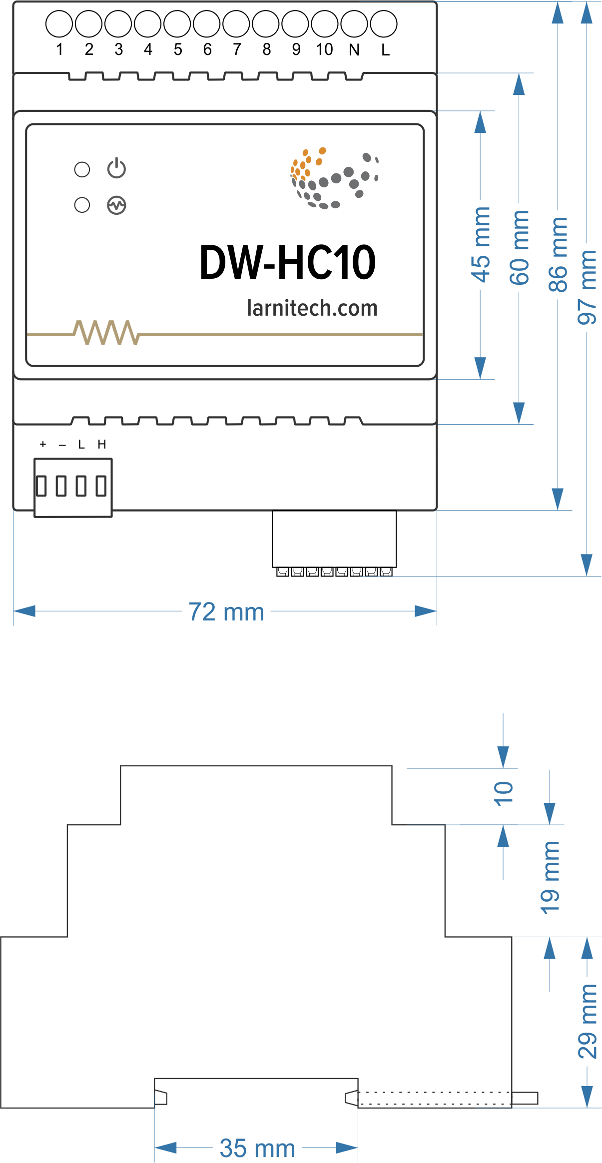
Module parameters
| Parameter name | Value |
|---|---|
| Input channels qty | 12 |
| Output channels qty | 10 |
| Load type | NO / NC / PWM (0.4Hz) |
| Supported sensors | DS18B20 / NTC (7-15kOhm) |
| Input voltage | 20-250V |
| Current type | AC/DC |
| Max load per channel | 0.5A(110W at 220V) |
| Max load per device | 1A(220W at 220V) |
| Power supply | 11.5 … 27.5 V DC from CAN |
| Max current(24V) | 110 mA |
| Sensors line max length | 30m |
| Bus type | CAN (4-wire) |
| Equipment installation type | DIN rail (EN 60715) |
| Case material | ABS |
| Protection | IP40 |
| Temperature range | -10 … +50 °C |
| Size | 4U, 69x110x58 mm |
| Weight | 140 g |
Connection of high load device
 |
Recomended contactors:
|
Input connector pinout

Example of sensors connection

Indication of module operation
Bootloader
| Indicator | Status | Description |
|---|---|---|
| Device in bootloader | ||
| Downloading firmware | ||
| Flashing firmware |
Firmware
| Indicator | Status | Description |
|---|---|---|
| Identification | ||
| Operational mode | ||
Error | ||
| Lost connection to server | ||
| Overheat | ||
| No AC power | ||
| RTC error |
Module installation and connection procedure
- Install the module in the switchboard on the DIN rail and fix it with the special latch on the module base.
- Connect the CAN connector.
- Connect the input/output channels.
- Configure the module using LT setup.
- Apply power to the load.
- Check all equipment for proper operation.
Module shut-off and deinstallation procedure
- Disconnect the power from the load.
- Disconnect the input/output channels.
- Disconnect the CAN connector.
- Remove the module from the DIN rail, releasing the latch at the bottom of the module base.
HW settings
| Name | Type, range | SUBID | Default | Description |
|---|---|---|---|---|
| def | string | 1-10 | 'OFF' | Def is the element status is set after restart, is used for lamp, heating, valve(1 pole);
Set 'last' saved state of the element in case of a power reset. The element save his state after stay unchanged for 10 minutes. Example: def='ON' def='last' |
| offset | integer -39 – 39 | 31-42 | 0 | It is the sensor values offset; Example: offset='-1.2' |
| mode | string | 98 | 'AС' | Output operatoin mode:
|
| out | char[10] | 98 | 'HHHHHHHHHH' | Each char is responsible for the type of a particular channel
Example: out='BGLKMVX' |
| in | char[12] | 98 | '++++++++++++' | Each char is responsible for the type of a particular channel
Example: out='+DR+R–R+RD+' |
| r | int | 31-42 | '10000' | Analogue temperature sensor`s resistance on 25 °C.
Example: r='8000' |
 1<item addr="348:1" cfgid="43" name="Jalousie" sub-type="120" type="jalousie" uniq_id="4097" hw="runtime=45"/>
 2<item addr="348:3" auto-period="600" cfgid="43" name="Lamp" type="lamp" uniq_id="4098" hw="def='ON'"/>
 3<item addr="348:4" cfgid="43" name="Gate" sub-type="120" type="gate" uniq_id="4099" hw="runtime=30"/>
 4<item addr="348:6" cfgid="43" name="Lock" type="lamp" uniq_id="4100" hw="hold=5000"/>
 5<item addr="348:7" cfgid="43" name="Radiator" type="valve-heating" uniq_id="4029" hw="def='ON'">
 6    <automation name="Eco" temperature-level="16" uniq_id="4030"/>
 7    <automation name="Comfort" temperature-level="22" uniq_id="4031"/>
 8    <automation name="Hot" temperature-level="25" uniq_id="4032"/>
 9</item>
10<item addr="348:8" cfgid="43" name="Radiator" type="valve-heating" uniq_id="4033" hw="def='OFF'">
11    <automation name="Eco" temperature-level="16" uniq_id="4034"/>
12    <automation name="Comfort" temperature-level="22" uniq_id="4035"/>
13    <automation name="Hot" temperature-level="25" uniq_id="4036"/>
14</item>
15<item addr="348:31" cfgid="43" name="Temperature" type="temperature-sensor" uniq_id="4089" hw="offset=10"/>
16<item addr="348:32" cfgid="43" name="Temperature" type="temperature-sensor" uniq_id="4090" hw="offset=-15"/>
17<item addr="348:33" cfgid="43" name="Temperature" type="temperature-sensor" uniq_id="4091"/>
18<item addr="348:34" cfgid="43" name="Temperature" type="temperature-sensor" uniq_id="4092" hw="offset=5"/>
19<item addr="348:35" cfgid="43" name="Temperature" type="temperature-sensor" uniq_id="4093"/>
20<item addr="348:36" cfgid="43" name="Temperature" type="temperature-sensor" uniq_id="4094"/>
21<item addr="348:37" cfgid="43" name="Temperature" type="temperature-sensor" uniq_id="4095"/>
22<item addr="348:38" cfgid="43" name="Temperature" type="temperature-sensor" uniq_id="4096"/>
23<item addr="348:39" cfgid="43" name="Temperature" type="temperature-sensor" uniq_id="4097"/>
24<item addr="348:40" cfgid="43" name="Temperature" type="temperature-sensor" uniq_id="4098"/>
25<item addr="348:97" cfgid="43" name="Temperature" system="yes" type="temperature-sensor" uniq_id="4041"/>
26<item addr="348:98" cfgid="43" hw="out='B-LG-KHJ--'" name="Temperature" system="yes" type="temperature-sensor" uniq_id="4042"/>