Difference between revisions of "DW-HC10/ru"
(Created page with "==Порядок установки и подключения модуля==") |
(Created page with "*Установите модуль в распределительный щит на DIN-рейку и закрепите специальной защелкой, распол...") |
||
| Line 112: | Line 112: | ||
==Порядок установки и подключения модуля== | ==Порядок установки и подключения модуля== | ||
| − | * | + | *Установите модуль в распределительный щит на DIN-рейку и закрепите специальной защелкой, расположенной на основании модуля. |
| − | * | + | *Подсоедините разъем CAN. |
| − | * | + | *Подключите входные/выходные каналы. |
| − | * | + | *Настройте модуль с помощью LT SETUP. |
| − | * | + | *Подайте питание на нагружаемые элементы системы. |
| − | * | + | *Проверьте все оборудование на правильность работы. |
==Module shut-off and deinstallation procedure== | ==Module shut-off and deinstallation procedure== | ||
Revision as of 11:45, 6 January 2022
| DW-HC10.C | |||||||
|---|---|---|---|---|---|---|---|
 | |||||||
| |||||||
| |||||||
10-ТИ КАНАЛЬНЫЙ КОНТРОЛЛЕР ОТОПЛЕНИЯ
Устройство предназначено для управления отопительными приборами (радиаторами, теплыми полами, фанкойлами и т. д.). Устройство оснащено 12-ю входными каналами для подключения датчиков температуры (FW-FT или FW-TS).
Функции
- 10 выходов для клапанов NO/NC/PWM
- 12 входов для цифровых/аналоговых датчиков температуры (FW-FT, FW-TS, NTC)
- Можно использовать данные о температуре из других модулей
- 10 независимых зон нагрева с недельным графиком
- До 20 отопительных профилей
- Встроенные часы реального времени
ВНИМАНИЕ! Все работы, связанные с установкой, подключением, настройкой, обслуживанием и поддержкой оборудования, должны выполняться только квалифицированным персоналом, обладающим достаточными навыками и опытом работы с электрооборудованием! Во избежание риска возгорания, поражения электрическим током, повреждения системы и/или травм, установка и сборка системы должны выполняться в соответствии с указаниями, перечисленными ниже:
- все работы по подключению должны выполняться при выключенном питании;
- необходимо использовать соответствующие инструменты и средства индивидуальной защиты от поражения электрическим током;
- запрещается использовать поврежденные кабели, провода и разъемы;
- избегайте перегиба проводов и кабелей;
- не прилагайте чрезмерных усилий к проводам путем их перегиба или слишком сильного сжатия: внутренние проводники кабелей и проводов могут быть оголены или повреждены;
- не используйте для подключения разъемы с плохими контактами;
- не превышайте параметры предельной нагрузки, указанные в инструкции;
- сечение питающих проводов зависит от требований к пределу плотности тока, типу изоляции и материалу проводов. Недостаточное сечение провода может привести к перегреву кабеля и возгоранию.
Когда питание включено, НИКОГДА:
- не подключайте/отключайте разъемы;
- не открывайте модули и датчики.
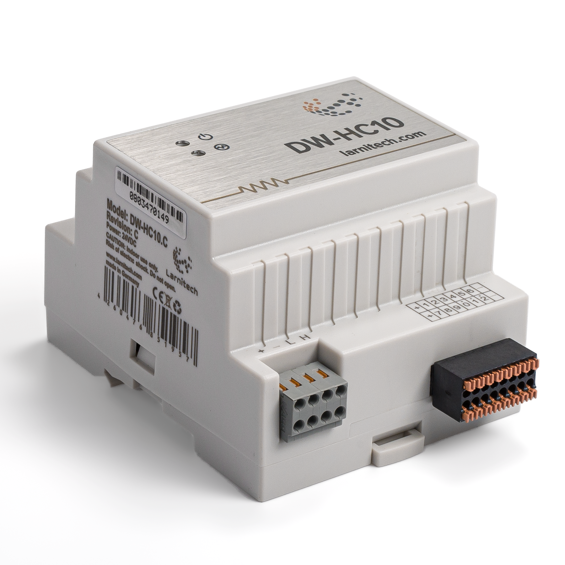
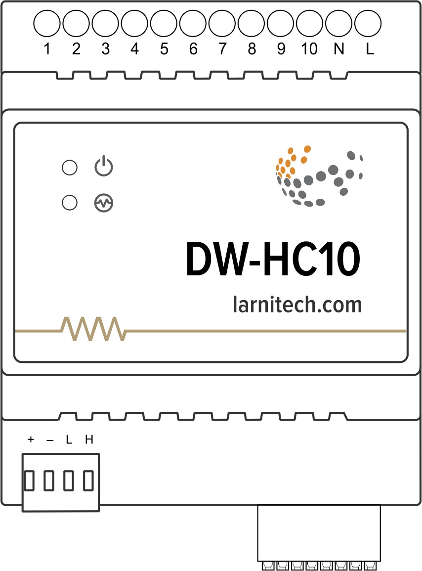
Изображение модуля
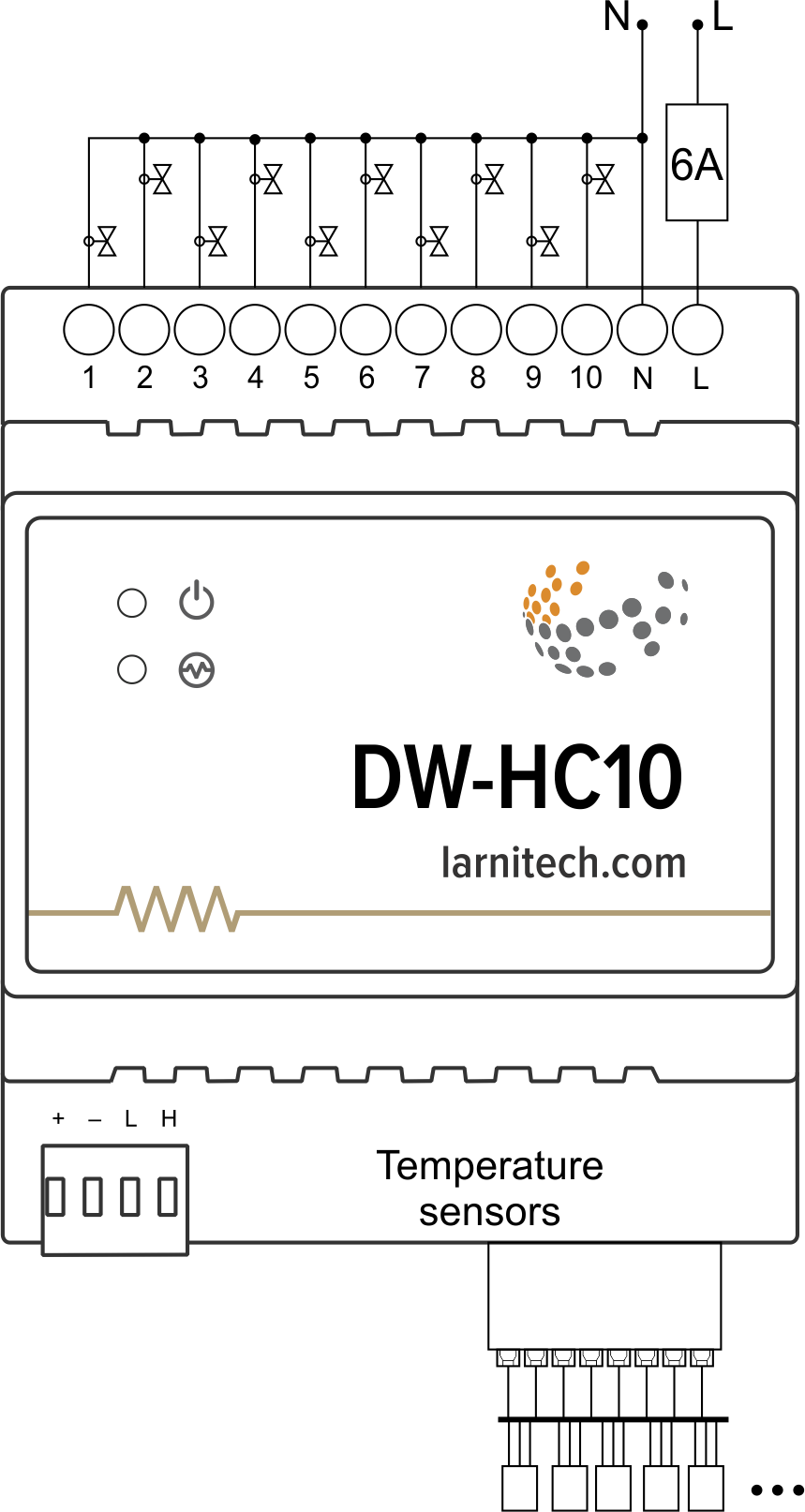
Пример подключения
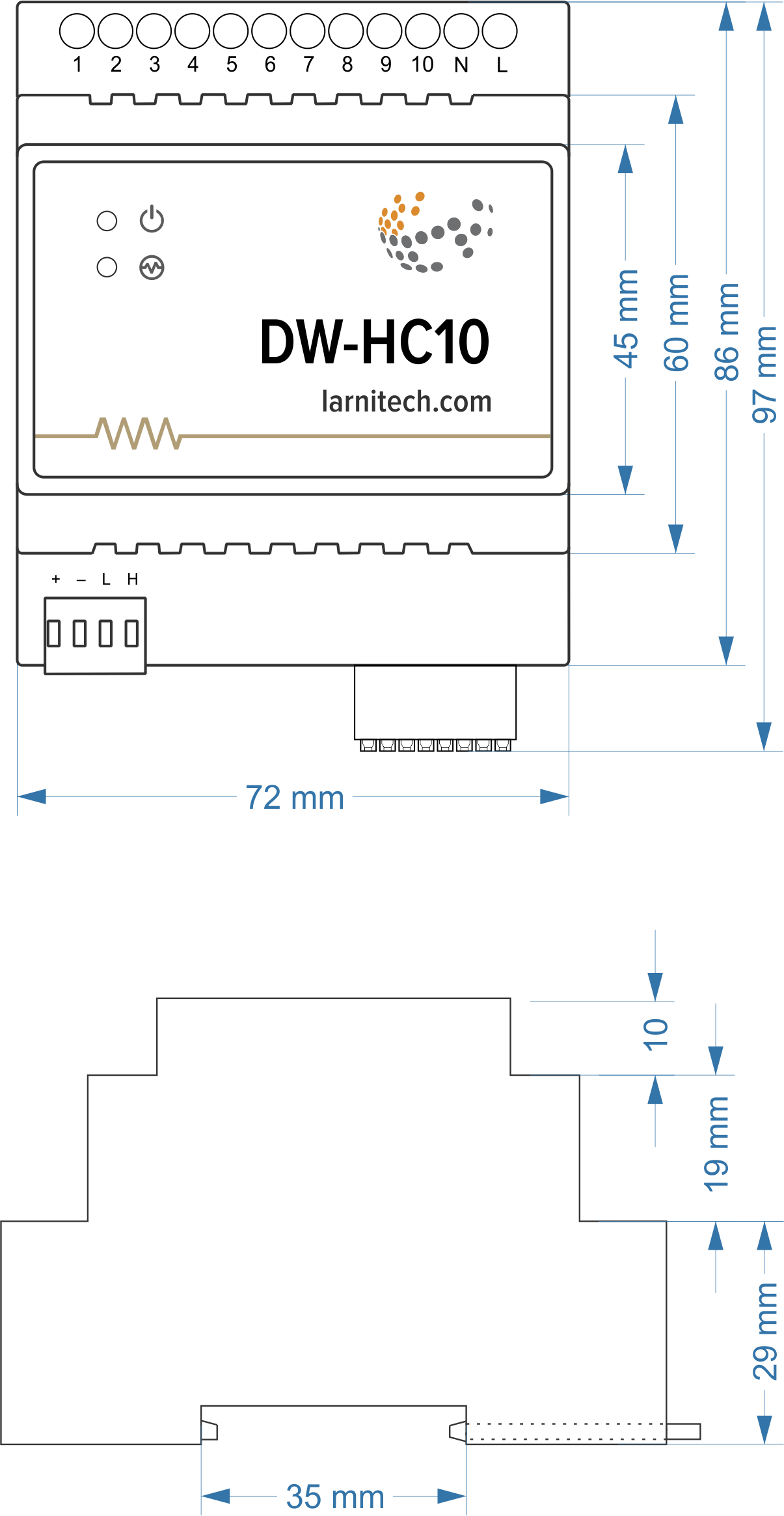
Размеры модуля
Параметры модуля
| Parameter name | Value |
|---|---|
| Input channels qty | 12 |
| Output channels qty | 10 |
| Load type | NO / NC / PWM (0.4Hz) |
| Supported sensors | DS18B20 / NTC (7-15kOhm) |
| Input voltage | 20-250V |
| Current type | AC/DC |
| Max load per channel | 0.5A(110W at 220V) |
| Max load per device | 1A(220W at 220V) |
| Power supply | 11.5 … 27.5 V DC from CAN |
| Max current(24V) | 110 mA |
| Sensors line max length | 30m |
| Bus type | CAN (4-wire) |
| Equipment installation type | DIN rail (EN 60715) |
| Case material | ABS |
| Protection | IP40 |
| Temperature range | -10 … +50 °C |
| Size | 4U, 69x110x58 mm |
| Weight | 140 g |
Подключение устройства с высокой нагрузкой
 |
style="margin:20px" | Рекомендуемые контакторы:
|
Внутренняя компоновка разъемов

Пример подключения датчиков

Индикация работы модуля
Загрузчик
| Indicator | Status | Description |
|---|---|---|
| Device in bootloader | ||
| Downloading firmware | ||
| Flashing firmware |
Прошивка
| Indicator | Status | Description |
|---|---|---|
| Identification | ||
| Operational mode | ||
Error | ||
| Lost connection to server | ||
| Overheat | ||
| No AC power | ||
| RTC error |
Порядок установки и подключения модуля
- Установите модуль в распределительный щит на DIN-рейку и закрепите специальной защелкой, расположенной на основании модуля.
- Подсоедините разъем CAN.
- Подключите входные/выходные каналы.
- Настройте модуль с помощью LT SETUP.
- Подайте питание на нагружаемые элементы системы.
- Проверьте все оборудование на правильность работы.
Module shut-off and deinstallation procedure
- Disconnect the power from the load.
- Disconnect the input/output channels.
- Disconnect the CAN connector.
- Remove the module from the DIN rail, releasing the latch at the bottom of the module base.
HW settings
| Name | Type, range | SUBID | Default | Description |
|---|---|---|---|---|
| def | string | 1-10 | 'OFF' | Def is the element status is set after restart, is used for lamp, heating, valve(1 pole);
Set 'last' saved state of the element in case of a power reset. The element save his state after stay unchanged for 10 minutes. Example: def='ON' def='last' |
| offset | integer -39 – 39 | 31-42 | 0 | It is the sensor values offset; Example: offset='-1.2' |
| mode | string | 98 | 'AС' | Output operatoin mode:
|
| out | char[10] | 98 | 'HHHHHHHHHH' | Each char is responsible for the type of a particular channel
Example: out='BGLKMVX' |
| in | char[12] | 98 | '++++++++++++' | Each char is responsible for the type of a particular channel
Example: out='+DR+R–R+RD+' |
| r | int | 31-42 | '10000' | Analogue temperature sensor`s resistance on 25 °C.
Example: r='8000' |
 1<item addr="348:1" cfgid="43" name="Jalousie" sub-type="120" type="jalousie" uniq_id="4097" hw="runtime=45"/>
 2<item addr="348:3" auto-period="600" cfgid="43" name="Lamp" type="lamp" uniq_id="4098" hw="def='ON'"/>
 3<item addr="348:4" cfgid="43" name="Gate" sub-type="120" type="gate" uniq_id="4099" hw="runtime=30"/>
 4<item addr="348:6" cfgid="43" name="Lock" type="lamp" uniq_id="4100" hw="hold=5000"/>
 5<item addr="348:7" cfgid="43" name="Radiator" type="valve-heating" uniq_id="4029" hw="def='ON'">
 6    <automation name="Eco" temperature-level="16" uniq_id="4030"/>
 7    <automation name="Comfort" temperature-level="22" uniq_id="4031"/>
 8    <automation name="Hot" temperature-level="25" uniq_id="4032"/>
 9</item>
10<item addr="348:8" cfgid="43" name="Radiator" type="valve-heating" uniq_id="4033" hw="def='OFF'">
11    <automation name="Eco" temperature-level="16" uniq_id="4034"/>
12    <automation name="Comfort" temperature-level="22" uniq_id="4035"/>
13    <automation name="Hot" temperature-level="25" uniq_id="4036"/>
14</item>
15<item addr="348:31" cfgid="43" name="Temperature" type="temperature-sensor" uniq_id="4089" hw="offset=10"/>
16<item addr="348:32" cfgid="43" name="Temperature" type="temperature-sensor" uniq_id="4090" hw="offset=-15"/>
17<item addr="348:33" cfgid="43" name="Temperature" type="temperature-sensor" uniq_id="4091"/>
18<item addr="348:34" cfgid="43" name="Temperature" type="temperature-sensor" uniq_id="4092" hw="offset=5"/>
19<item addr="348:35" cfgid="43" name="Temperature" type="temperature-sensor" uniq_id="4093"/>
20<item addr="348:36" cfgid="43" name="Temperature" type="temperature-sensor" uniq_id="4094"/>
21<item addr="348:37" cfgid="43" name="Temperature" type="temperature-sensor" uniq_id="4095"/>
22<item addr="348:38" cfgid="43" name="Temperature" type="temperature-sensor" uniq_id="4096"/>
23<item addr="348:39" cfgid="43" name="Temperature" type="temperature-sensor" uniq_id="4097"/>
24<item addr="348:40" cfgid="43" name="Temperature" type="temperature-sensor" uniq_id="4098"/>
25<item addr="348:97" cfgid="43" name="Temperature" system="yes" type="temperature-sensor" uniq_id="4041"/>
26<item addr="348:98" cfgid="43" hw="out='B-LG-KHJ--'" name="Temperature" system="yes" type="temperature-sensor" uniq_id="4042"/>