Difference between revisions of "DW-HT05/ru"
(Created page with "===Подключение устройства с высокой нагрузкой===") |
(Created page with "{| class="wikitable" style="width:800px"; |- |200px|Contactor|| style="margin:20px"|Рекомендуемые контакторы: *ABB серии ESB...") |
||
| Line 102: | Line 102: | ||
{| class="wikitable" style="width:800px"; | {| class="wikitable" style="width:800px"; | ||
|- | |- | ||
| − | |[[File:Contactor.png|200px|Contactor]]|| style="margin:20px"| | + | |[[File:Contactor.png|200px|Contactor]]|| style="margin:20px"|Рекомендуемые контакторы: |
| − | *ABB ESB | + | *ABB серии ESB |
| − | *Schneider Acti 9 iCT | + | *Schneider Acti 9 серии iCT |
| − | *Hager ESC | + | *Hager серии ESC. |
|} | |} | ||
Revision as of 12:04, 5 January 2022
| DW-HT05.C | |||||||
|---|---|---|---|---|---|---|---|
 | |||||||
| |||||||
| |||||||
5-ТИ КАНАЛЬНЫЙ МОДУЛЬ РАСШИРЕНИЯ
Снабжен 5-ю выходами для подключения нагрузки и 12-ю входами для подключения различных датчиков/кнопок.
Функции
- 5 универсальных выходов обеспечивают управление:
- Освещением
- Клапанами отопления NC/NO
- Жалюзи
- 1- или 2-х полюсными воротами
- 1- или 2-х полюсными клапанами
- Замками NC/NO
- Фанкойлами
- 12 отдельных входов обеспечивают управление:
- Кнопками
- Выключателями
- Герконами
- Датчиками протечки
- Детекторами движения
ВНИМАНИЕ! Все работы, связанные с установкой, подключением, настройкой, обслуживанием и поддержкой, должны выполняться квалифицированным персоналом, имеющим достаточные навыки и опыт работы с электрооборудованием. Во избежание риска возгорания, поражения электрическим током, повреждения системы и/или травм, установка и сборка системы должны выполняться в соответствии с инструкциями, перечисленными ниже:
- все работы по подключению должны производиться на обесточенном оборудовании;
- необходимо использовать соответствующие инструменты и средства индивидуальной защиты от поражения электрическим током;
- запрещается использовать поврежденные кабели, провода и разъемы;
- избегайте перегиба проводов и кабелей;
- не пережимайте и не перегибайте кабели и провода, прилагая чрезмерные усилия. В противном случае внутренние проводники кабеля и проводов могут быть оголены или повреждены;
- не используйте для подключения разъемы с плохими контактами;
- не превышайте предельные параметры нагрузки, указанные в данном руководстве;
- сечение питающих проводов зависит от требований к пределу плотности тока, типу изоляции и материалу проводов. Недостаточное сечение может привести к перегреву кабеля и возгоранию.
При работе с системой после подачи напряжения НИКОГДА:
- не производите подключение/отключение разъемов;
- не открывайте модули и датчики.
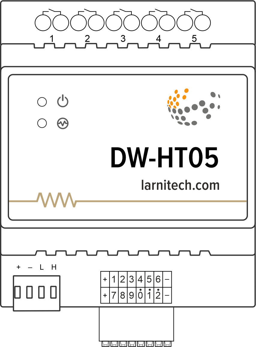
Общая схема модуля
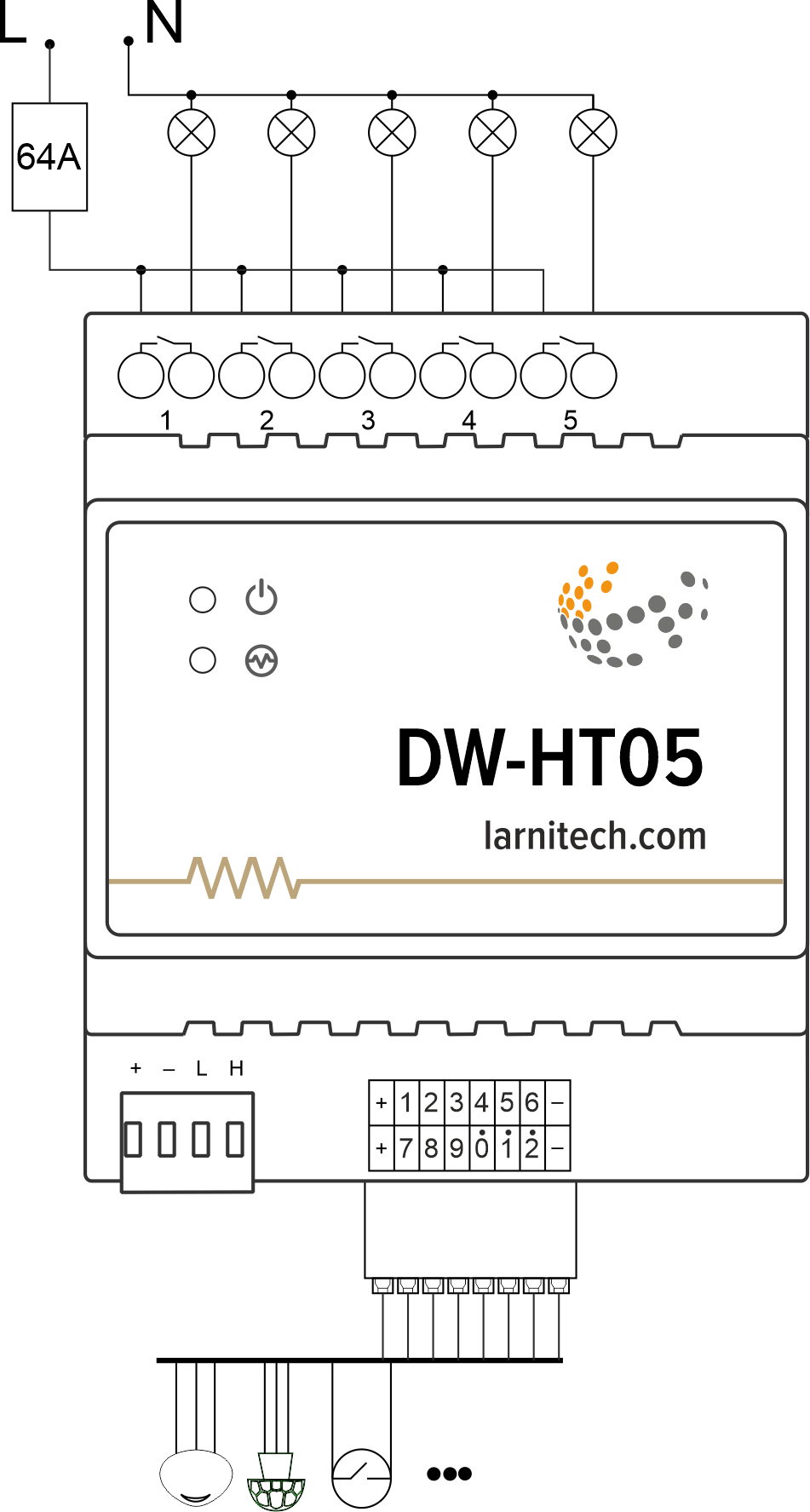
Пример подключения
Размеры модуля
Параметры модуля
| Parameter name | Value |
|---|---|
| Output channels qty | 5 |
| Discrete input channels qty | 12 |
| Input voltage | 0-250V |
| Current type | AC/DC |
| Max load per channel | 16A |
| Power supply | 11.5 … 27.5 V DC from CAN |
| Max current(24V) | 110 mA |
| Bus type | CAN |
| Equipment installation type | DIN rail (EN 60715) |
| Case material | ABS |
| Protection | IP40 |
| Temperature range | -10 … +50 °C |
| Size | 4U, 69x110x58 mm |
| Weight | 110 g |
Рекомендации по подключению
Для защиты реле и подключенных к нему нагрузок рекомендуется установить автоматический выключатель. Номинальное значение автоматического выключателя следует рассчитывать исходя из максимальной общей нагрузки подключенных устройств, и при этом оно не должно значительно превышать максимально допустимые характеристики реле. В зависимости от требований вы можете использовать один автоматический выключатель на одно реле (рекомендуется) или один автоматический выключатель на каждую группу подключенных нагрузок, или, при необходимости, можно установить отдельный автоматический выключатель для каждой нагрузки.
Подключение реле
Подключение термореле освещения/электрического контактора/отопления
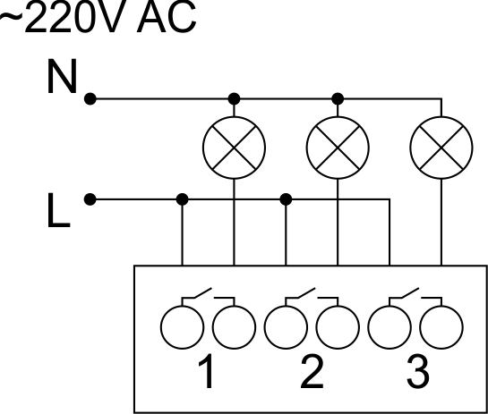
Пример HW для этой конфигурации
1hw="out='LLL--'"
Подключение устройства с высокой нагрузкой
 |
Рекомендуемые контакторы:
|
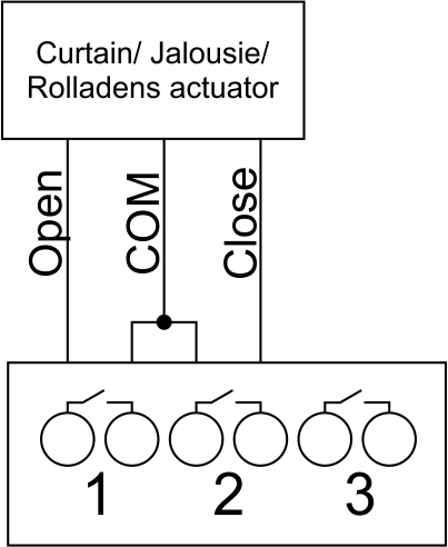
Connection of curtain/jalousie/shutter actuator with 220V force control
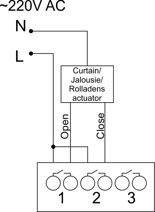
Sample HW for this configuration
1hw="out='B----'"
Connection of curtain/jalousie/shutter actuator with low-voltage control
Sample HW for this configuration
1hw="out='B----'"
Connection of single-pole gate actuator
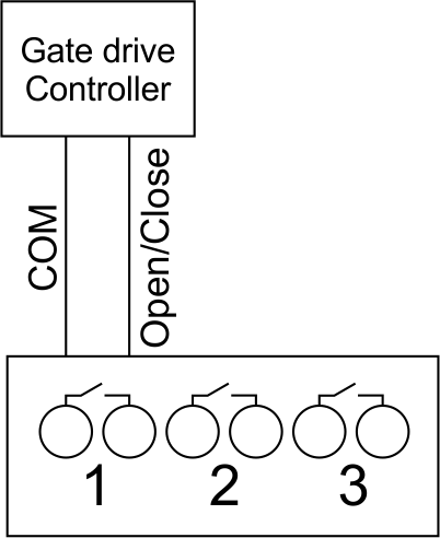
Sample HW for this configuration
1hw="out='X----'"
Connection of double-pole gate actuator
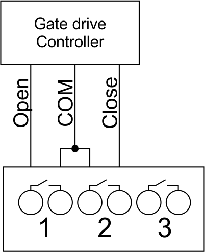
Sample HW for this configuration
1hw="out='G----'"
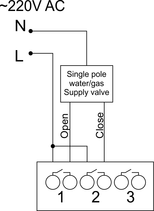
Connection of single-pole water/gas supply valve
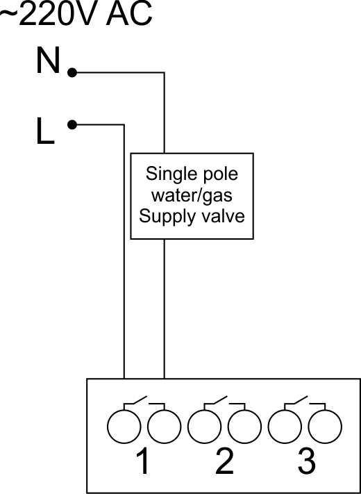
Sample HW for this configuration
1hw="out='R----'"
Connection of double-pole water/gas supply valve
Sample HW for this configuration
1hw="out='V----'"
Connection of fancoil control unit
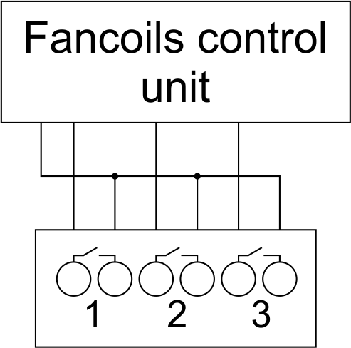
Sample HW for this configuration
1hw="out='FFF--'"
Indication of module operation
Bootloader
| Indicator | Status | Description |
|---|---|---|
| Device in bootloader | ||
| Downloading firmware | ||
| Flashing firmware |
Firmware mode
| Indicator | Status | Description |
|---|---|---|
| Identification | ||
| Operational mode | ||
Error | ||
| Lost connection to server | ||
| Overheat |
Module installation and connection procedure
- Connect the outputs.
- Connect the inputs.
- Connect the Can connector.
- Configure the module using LT setup.
- Apply power to the load
- Check all equipment for proper operation.
Module shut-off and deinstallation procedure
- Disconnect the power from the load
- Disconnect the CAN connector.
- Disconnect the inputs.
- Disconnect the outputs.
HW Settings
| Name | Type, range | SUBID | Default | Description |
|---|---|---|---|---|
| runtime | integer 0-100 | 1-5 | 15 | runtime is the open/close time in seconds, is used for jalousie, gate, valve(2 pole); Example: runtime=15 |
| runtimeopen | integer 0-60000 | Blinds subId | - | Runtimeopen is the open time in milliseconds, is used for blinds; Example: runtimeopen=15000 |
| runtimeclose | integer 0-60000 | Blinds subId | - | Runtimeclose is the close time in milliseconds, is used for blinds; Example: runtimeclose=15000 |
| hold | integer 0-10000 | 1-5 | 500 | hold is the bridging time in miliseconds, is used for gate and jalousie (by default hold is the same as runtime), lock; Example: hold=3500 |
| def | string 'ON' | 1-5 | 'OFF' | def is the element status is set after restart, is used for lamp, heating, valve(1 pole); Example: def='ON' |
| stop | Char ‘R’ | 1-5 | – | (for 2-pole gate and blinds) If it is declared then by Stop command during the motion, the same impulse appears as it was at the beginning of the motion. Pole, an which the stop-impules is formed, is defined by the parameter Stop value. If it is ‘r’ or ‘R’ then stop-impulse is produced on the opposite to the start-impulse pole. If any other value is delcared (e.g., ‘d’ ) then the stop-impulse is on the same pole. If a Runtime passed after the beginning of the motion then the stop-impulse is not formed. Example: stop=’r’ |
| out | char[5] | 98 | 'LLLLL' | Each char is responsible for the type of a particular channel
Example: out='LLHHHG-' |
| offset | float | SubID of OW temperature sensors | '0' | [+/- 0..39] – sensor values offset;
For example, offset is -3.8 : hw="offset='-3.8'" |
| in | char[12] | 98 | 'KKKKKKKKKKKK' | Each char is responsible for the type of a particular channel
Example: in='KKKBBBLLLMMM' |
 1<item addr="331:1" auto-period="600" cfgid="41" name="Lamp" type="lamp" hw="def='ON'" uniq_id="189"/>
 2<item addr="331:2" cfgid="41" name="Jalousie" sub-type="120" type="jalousie" hw="runtime=35" uniq_id="190"/>
 3<item addr="331:4" cfgid="41" name="Valve" type="valve" hw="runtime=44" uniq_id="191"/>
 4<item addr="331:11" cfgid="41" name="Motion" type="motion-sensor" uniq_id="192"/>
 5<item addr="331:12" cfgid="41" name="Leak" type="leak-sensor" uniq_id="193"/>
 6<item addr="331:13" cfgid="41" name="Leak" type="leak-sensor" uniq_id="194"/>
 7<item addr="331:14" cfgid="41" name="Switch" type="switch" uniq_id="195"/>
 8<item addr="331:15" cfgid="41" name="Switch" type="switch" uniq_id="196"/>
 9<item addr="331:16" cfgid="41" name="Door" type="door-sensor" uniq_id="184"/>
10<item addr="331:18" cfgid="41" name="Door" type="door-sensor" uniq_id="186"/>
11<item addr="331:97" cfgid="41" name="Temperature" system="yes" type="temperature-sensor" uniq_id="187"/>
12<item addr="331:98" cfgid="41" hw="out='LB-V-' in='MLNSB----H-K'" name="Temperature" system="yes" type="temperature-sensor" uniq_id="188"/>