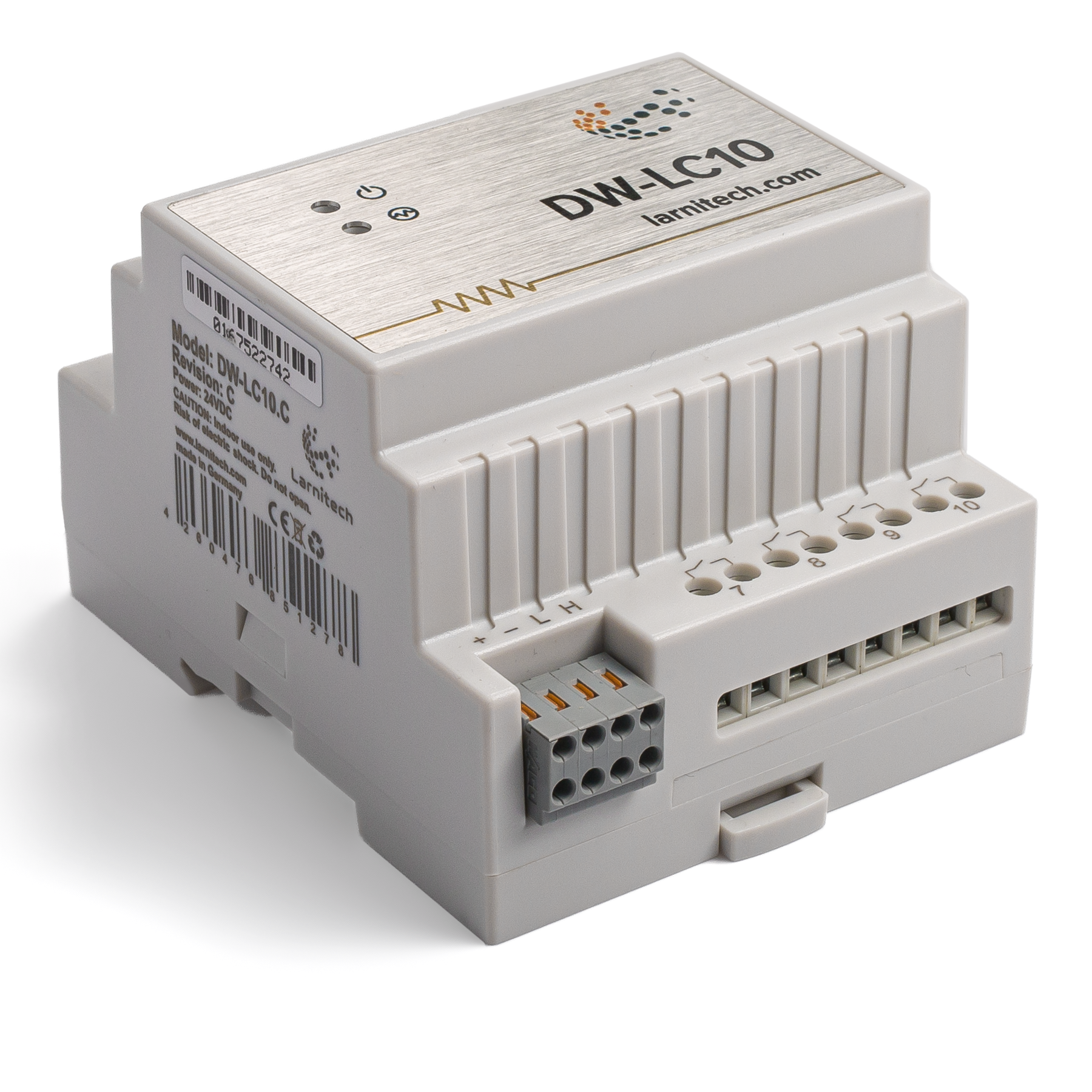
DW-LC10
| DW-LC10.C | |||||||
|---|---|---|---|---|---|---|---|
 | |||||||
| |||||||
10-ТИ КАНАЛЬНОЕ РЕЛЕ
Модуль предназначен для коммутации цепей постоянного и переменного тока большой мощности. Применяется для управления освещением, эл. розетками, фанкойлами, замками, жалюзи/воротами.
Функции
- Управление широким спектром устройств:
- Освещение
- Клапаны отопления НЗ/НО
- Жалюзи
- 1- или 2-х полюсные ворота
- 1- или 2-х полюсные клапаны
- Замки NC/NO
- Фанкойлы
- Реле с контактами AgSnO2 рассчитаны на постоянную нагрузку 16 А и пиковую нагрузку до 120 А 20 мс
- Переключение реле с низким уровнем шума
- Встроенный логический модуль
- Поддержка технологии Plug&Play
- Регулярные обновления программного обеспечения
CAUTION! All work related to the installation, connection, setting up, service and support must be carried out by qualified personnel with sufficient skills and experience in working with electrical equipment. To avoid the risk of fire, electric shock, damage to the system and/or personal injury, the system installation and assembly must be performed in accordance with the instructions listed below:
- all connectivity work must be carried out with the power turned OFF;
- use appropriate tools and personal protection against electric shock;
- do not use damaged cables, wires and connectors;
- avoid folding the cables and wires;
- do not apply excessive force to the wires by kinking or pressing them too hard: the inner conductors of the cables and wires may get stripped or damaged;
- do not use the power socket with poor contacts to connect;
- do not exceed the load limit parameters specified in the manual;
- the supply conductors wire section is subject to the specifications for current density limit, insulation type and wire material. Light section can result in cable overheating and fire.
When the power is on, NEVER:
- connect/disconnect the connectors;
- open modules and sensors.
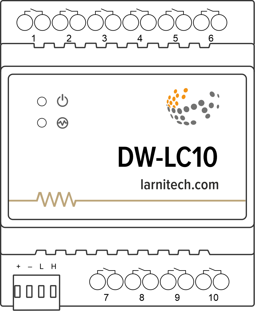
Overview
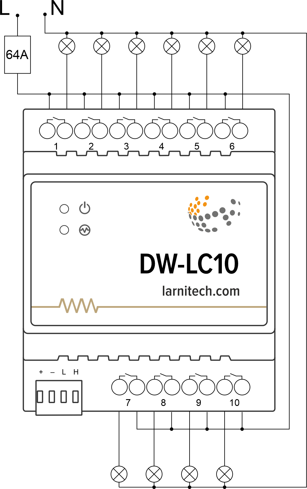
Example of connection
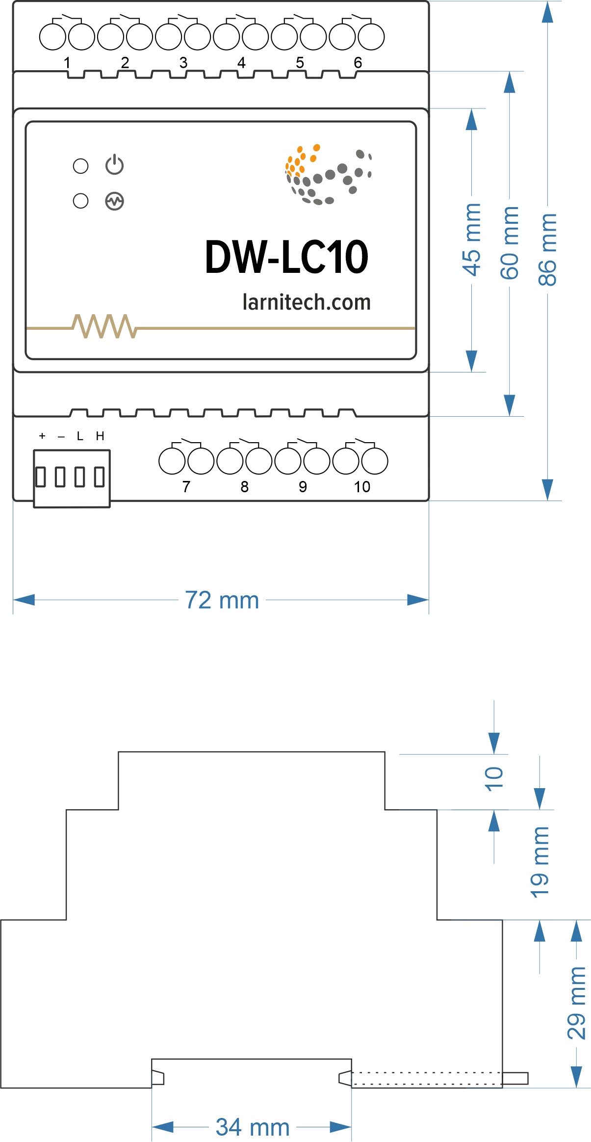
Module dimensions
Module parameters
| Parameter name | Value |
|---|---|
| Output channels qty | 10 |
| Input voltage | 0-250V |
| Current type | AC/DC |
| Max load per channel | 16A |
| Power supply | 11.5 … 27.5 V DC from CAN |
| Max current(24V) | 200 mA |
| Permissible section of power supply cable to connect in socket: single-conductor cable multiple-conductor cable tipped multiple-conductor cable |
0.5 … 4mm2 0.5 … 4mm2 0.5 … 2.5mm2 |
| Bus type | CAN (4-wire) |
| Equipment installation type | DIN rail (EN 60715) |
| Case material | ABS |
| Protection | IP40 |
| Temperature range | -10 … +50 °C |
| Size | 4U, 69x115x58 mm |
| Weight | 250 g |
Connectivity recommendations
In order to protect the actuator and loads connected to it, installing a circuit breaker is recommended. The nominal value of the circuit breaker should be calculated based on the maximum total load of connected devices and at the same time should not significantly exceed the maximum permissible characteristics of the actuator. Depending on the requirements, you can use one circuit breaker for one actuator (it is recommended) or one circuit breaker per each group of connected loads, or, if necessary, a separate circuit breaker can be installed for each load.
Connection of actuators
Connection of the lights/electric contactor/heating thermal actuator
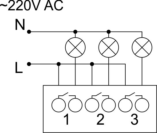
Sample HW for this configuration
1hw="out='LLL-------'"
Connection of high load device
 |
Recomended contactors:
|
Connection of curtain/jalousie/shutter actuator with 220V force control
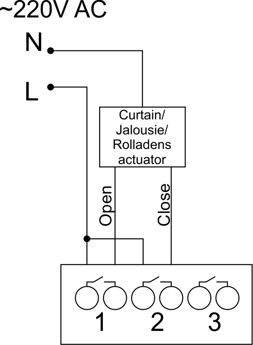
Sample HW for this configuration
1hw="out='B---------'"
Connection of curtain/jalousie/shutter actuator with low-voltage control
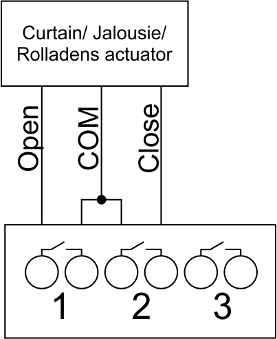
Sample HW for this configuration
1hw="out='B---------'"
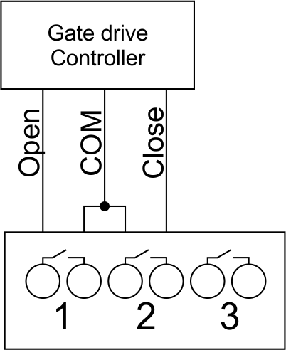
Connection of single-pole gate actuator
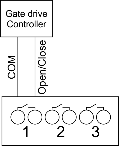
Sample HW for this configuration
1hw="out='X---------'"
Connection of double-pole gate actuator
Sample HW for this configuration
1hw="out='G---------'"
Connection of single-pole water/gas supply valve
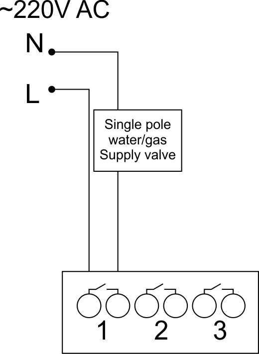
Sample HW for this configuration
1hw="out='R---------'"
Connection of double-pole water/gas supply valve
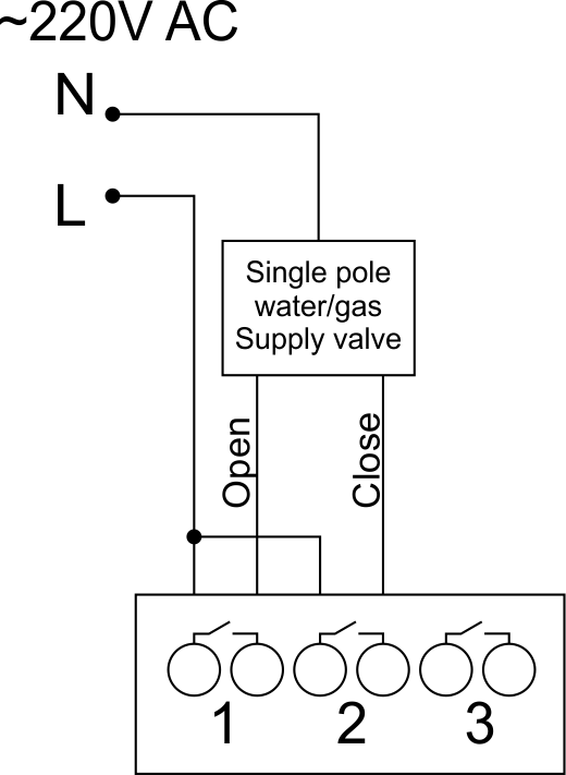
Sample HW for this configuration
1hw="out='V---------'"
Connection of fancoil control unit
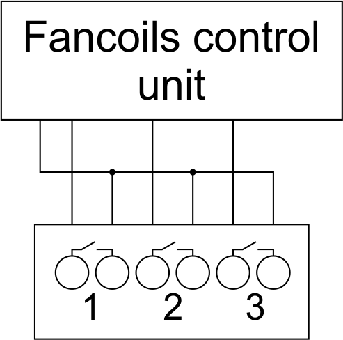
Sample HW for this configuration
1hw="out='FFF-------'"
Indication of module operation
Bootloader
| Indicator | Status | Description |
|---|---|---|
| Device in bootloader | ||
| Downloading firmware | ||
| Flashing firmware |
Firmware
| Indicator | Status | Description |
|---|---|---|
| Identification | ||
| Operational mode | ||
Error | ||
| Lost connection to server | ||
| Overheat |
Module installation and connection procedure
- Install the module in the switchboard on the DIN rail and fix it with the special latch on the module base.
- Connect the CAN connector.
- Connect the channels (1-10).
- Configure the module using LT setup.
- Apply power to the load.
- Check all equipment for proper operation.
Module shut-off and deinstallation procedure
- Disconnect the power from the load.
- Disconnect the channels (1-10).
- Disconnect the CAN connector.
- Remove the module from the DIN rail, releasing the latch at the bottom of the module base.
HW settings
| Name | Type, range | SUBID | Default | Description |
|---|---|---|---|---|
| runtime | integer 0-100 | 1-10 | 15 | runtime is the open/close time in seconds, is used for jalousie, gate, valve(2 pole); Example: runtime=15 |
| runtimeopen | integer 0-60000 | Blinds subId | – | Runtimeopen is the open time in milliseconds, is used for blinds; Example: runtimeopen=15000 |
| runtimeclose | integer 0-60000 | Blinds subId | – | Runtimeclose is the close time in milliseconds, is used for blinds; Example: runtimeclose=15000 |
| hold | integer 0-10000 | 1-10 | 500 | hold is the bridging time in miliseconds, is used for gate and jalousie (by default hold is the same as runtime), lock; Example: hold=3500 |
| def | string 'ON' | 1-10 | 'OFF' | def is the element status is set after restart, is used for lamp, heating, valve(1 pole); Example: def='ON' |
| stop | Char ‘R’ | 1-9 | – | (for 2-pole gate and blinds) If it is declared then by Stop command during the motion, the same impulse appears as it was at the beginning of the motion. Pole, an which the stop-impules is formed, is defined by the parameter Stop value. If it is ‘r’ or ‘R’ then stop-impulse is produced on the opposite to the start-impulse pole. If any other value is delcared (e.g., ‘d’ ) then the stop-impulse is on the same pole. If a Runtime passed after the beginning of the motion then the stop-impulse is not formed. Example: stop=’r’ |
| out | char[10] | 98 | 'LLLLLLLLLL' | Each char is responsible for the type of a particular channel
Example: out='BGLKMVX' |
 1<item addr="300:1" cfgid="98" hw="runtime=60" name="Jalousie" sub-type="120" type="jalousie" uniq_id="117"/>
 2<item addr="300:3" auto-period="600" cfgid="98" hw="def='ON'" name="Lamp" type="lamp" uniq_id="110"/>
 3<item addr="300:4" cfgid="98" hw="runtime=30" name="Gate" sub-type="120" type="gate" uniq_id="118"/>
 4<item addr="300:6" auto-period="600" cfgid="98" hw="hold=5000" name="Lamp" type="lamp" uniq_id="113"/>
 5<item addr="300:7" cfgid="98" hw="def='ON'" name="Radiator" type="valve-heating" uniq_id="119">
 6    <automation name="Eco" temperature-level="16" uniq_id="120"/>
 7    <automation name="Comfort" temperature-level="22" uniq_id="121"/>
 8    <automation name="Hot" temperature-level="25" uniq_id="122"/>
 9</item>
10<item addr="300:8" cfgid="98" hw="def='ON'" name="Radiator" type="valve-heating" uniq_id="123">
11    <automation name="Eco" temperature-level="16" uniq_id="124"/>
12    <automation name="Comfort" temperature-level="22" uniq_id="125"/>
13    <automation name="Hot" temperature-level="25" uniq_id="126"/>
14</item>
15<item addr="300:10" cfgid="98" hw="hold=2000" name="Gate" sub-type="120" type="gate" uniq_id="127"/>
16<item addr="300:97" cfgid="98" name="Temperature" system="yes" type="temperature-sensor" uniq_id="106"/>
17<item addr="300:98" cfgid="98" hw="out='BLGKHJ-X'" name="Temperature" system="yes" type="temperature-sensor" uniq_id="107"/>