Difference between revisions of "DW-RGB03/ru"
Jump to navigation
Jump to search
(Created page with "==Параметры модуля==") |
(Created page with "==Индикация работы модуля== ===Загрузчик=== {{indication| textBBB= Ожидание команды загрузчика}} ===Прошивка===...") |
||
| Line 84: | Line 84: | ||
}} | }} | ||
| − | == | + | ==Индикация работы модуля== |
| − | === | + | ===Загрузчик=== |
| − | {{indication| textBBB= | + | {{indication| textBBB= Ожидание команды загрузчика}} |
| − | === | + | ===Прошивка=== |
{{indicationfw | {{indicationfw | ||
|err1 = 1 | |err1 = 1 | ||
Revision as of 12:55, 6 January 2022
| DW-RGB03.C | |||||||
|---|---|---|---|---|---|---|---|
 | |||||||
| |||||||
9-ТИ КАНАЛЬНЫЙ КОНТРОЛЛЕР СВЕТОДИОДНОГО ОСВЕЩЕНИЯ
Модуль позволяет подключать RGB-ленты и монохромные светодиодные ленты.
Функции
- Поддерживаемые типы нагрузки:
- 9 монохромных каналов
- 3 канала RGB
- 2 канала RGBW + 1 монохромный канал
- 1 канал RGBWW + 1 канал RGB или 4 монохромных канала
ВНИМАНИЕ! Все работы, связанные с установкой, подключением, настройкой, обслуживанием и поддержкой оборудования, должны выполняться только квалифицированным персоналом, обладающим достаточными навыками и опытом работы с электрооборудованием! Во избежание риска возгорания, поражения электрическим током, повреждения системы и/или травм, установка и сборка системы должны выполняться в соответствии с указаниями, перечисленными ниже:
- все работы по подключению должны выполняться при выключенном питании;
- необходимо использовать соответствующие инструменты и средства индивидуальной защиты от поражения электрическим током;
- запрещается использовать поврежденные кабели, провода и разъемы;
- избегайте перегиба проводов и кабелей;
- не прилагайте чрезмерных усилий к проводам путем их перегиба или слишком сильного сжатия: внутренние проводники кабелей и проводов могут быть оголены или повреждены;
- не используйте для подключения разъемы с плохими контактами;
- не превышайте параметры предельной нагрузки, указанные в инструкции;
- сечение питающих проводов зависит от требований к пределу плотности тока, типу изоляции и материалу проводов. Недостаточное сечение провода может привести к перегреву кабеля и возгоранию.
Когда питание включено, НИКОГДА:
- не подключайте/отключайте разъемы;
- не открывайте модули и датчики.
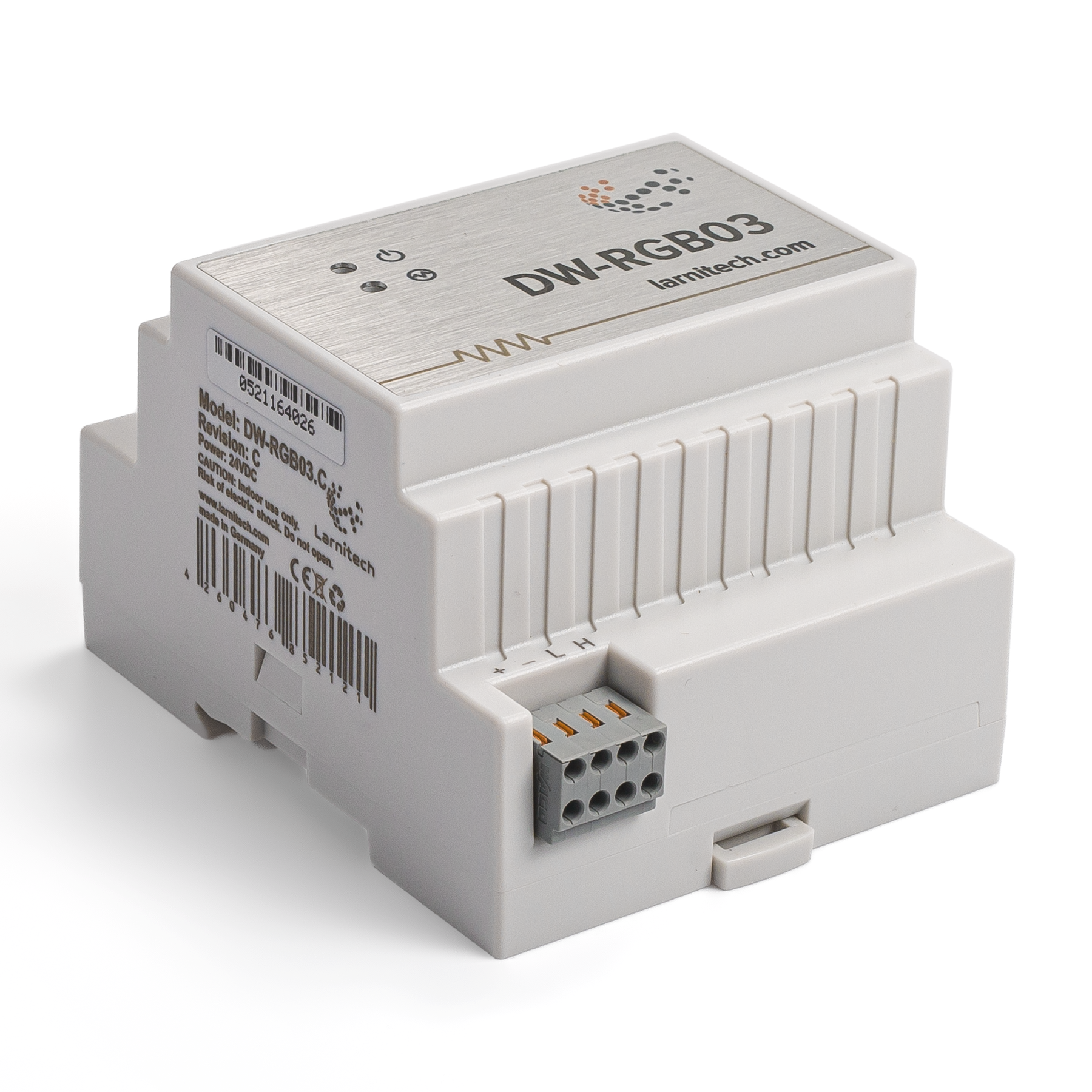
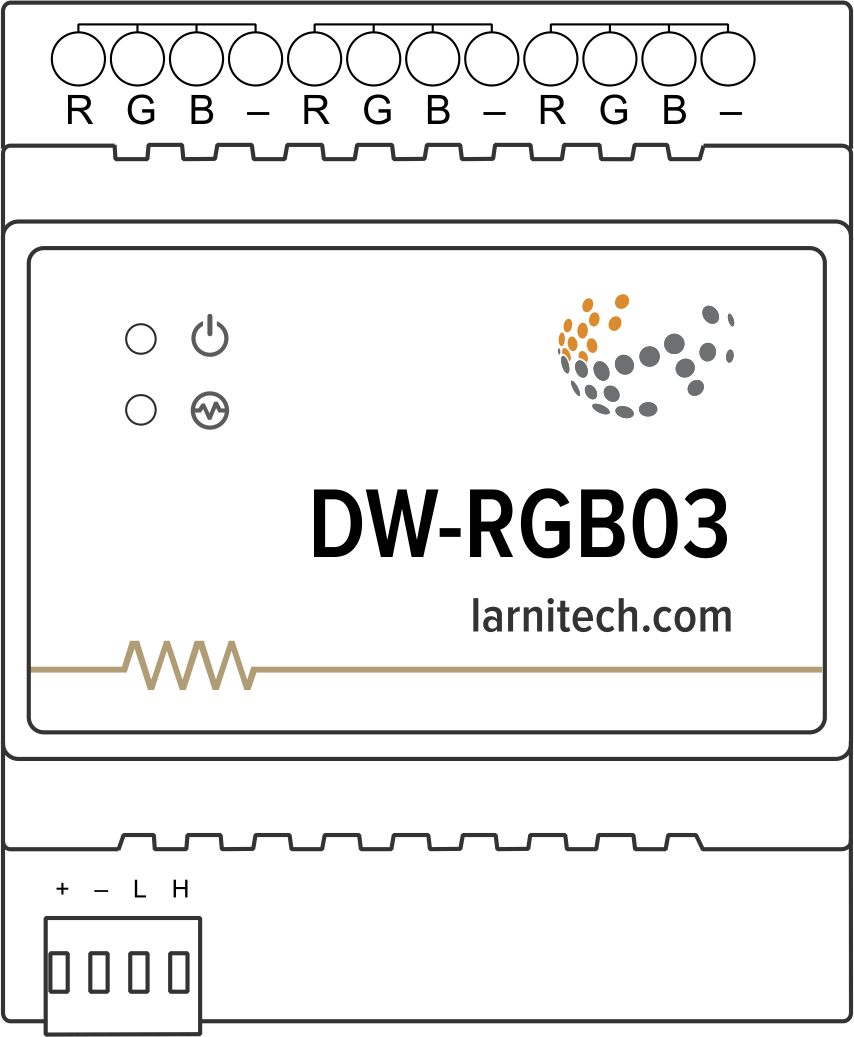
Изображение модуля
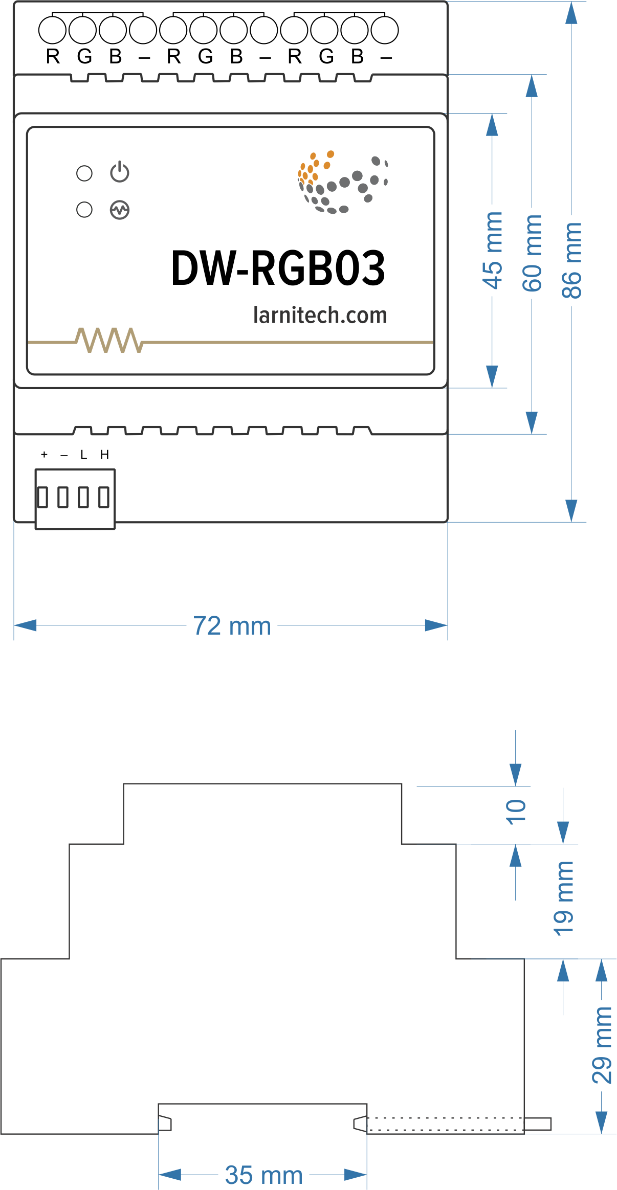
Размеры модуля
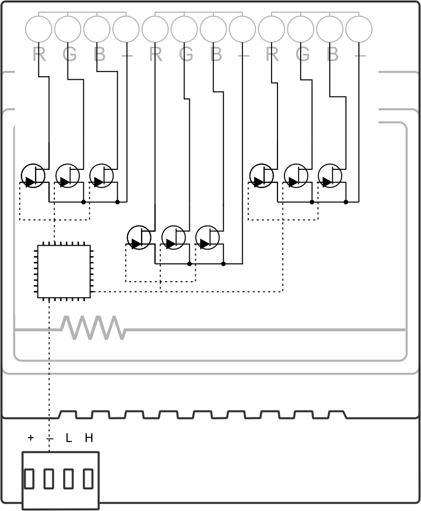
Внутренняя компоновка
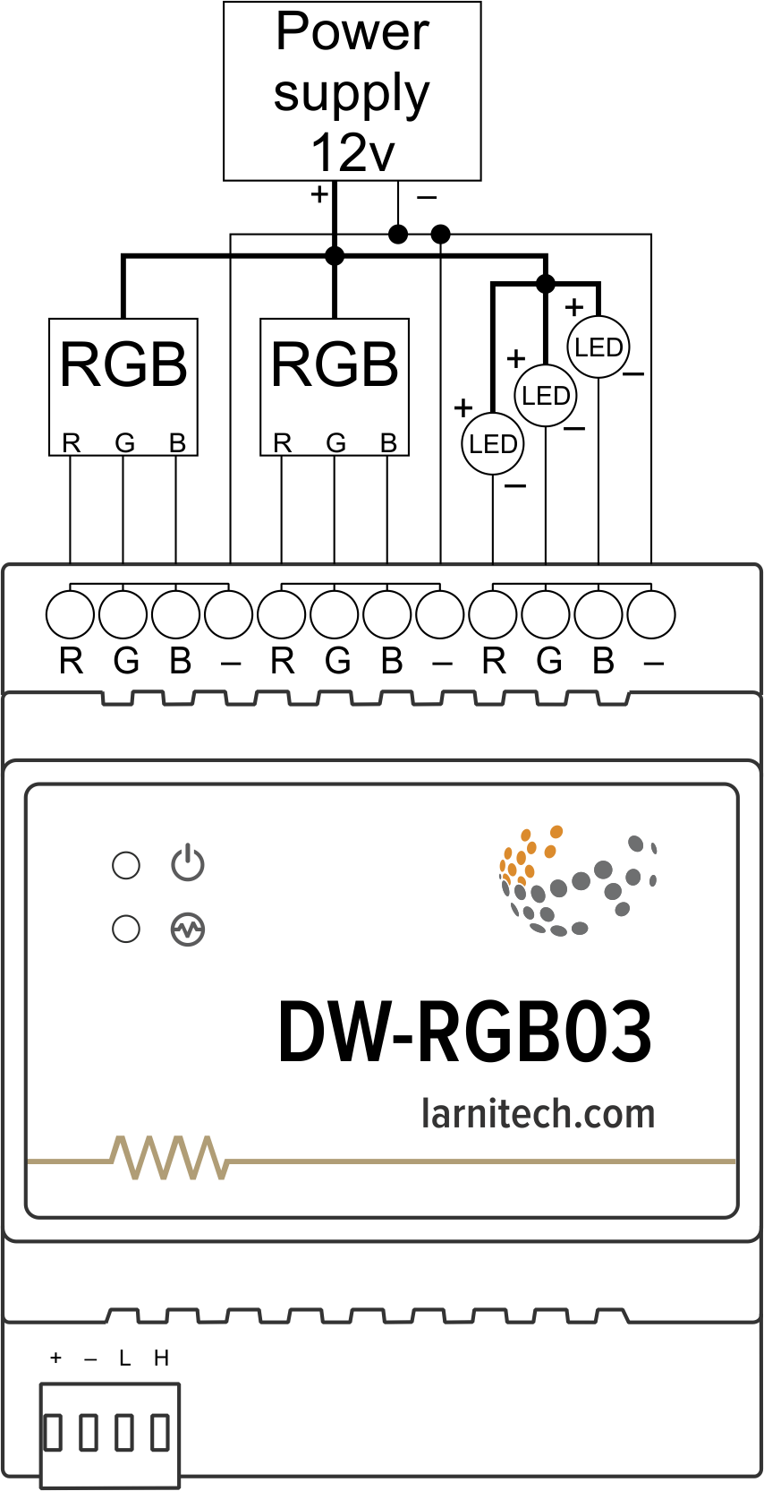
Подключение светодиодных ламп и RGB светодиодов
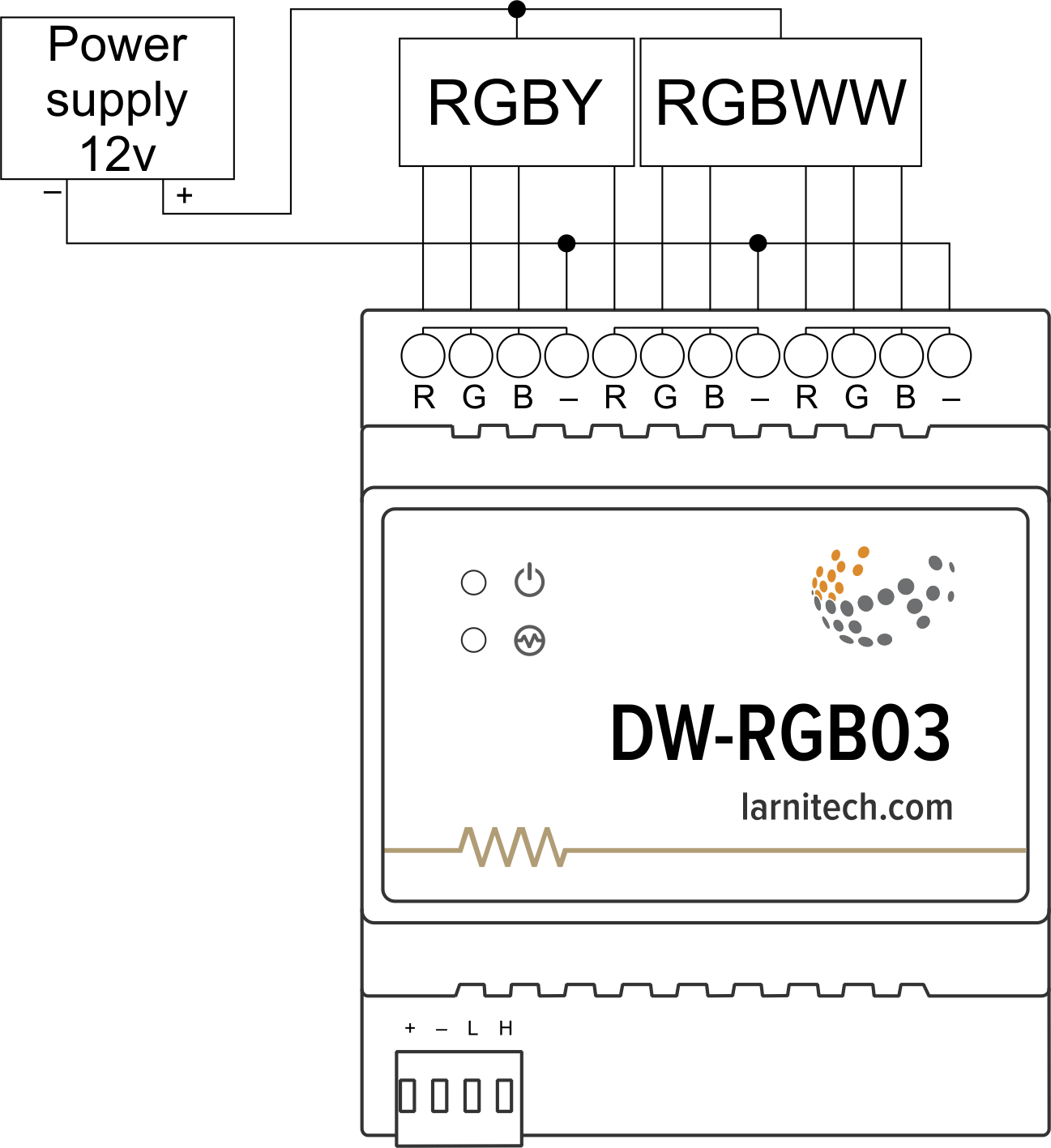
Пример подключения RGBWW/RGBW светодиодов
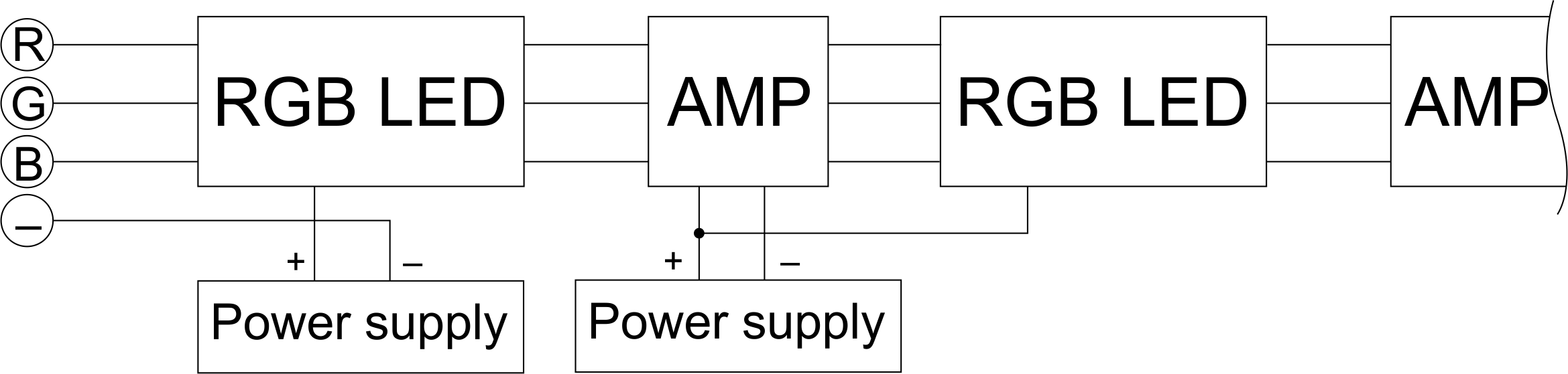
Пример подключения RGB светодиодов с усилителем
Параметры модуля
| Parameter name | Value |
|---|---|
| Output channels qty | 9 |
| Input voltage | 0...25V DC |
| Current type | DC |
| Adjustment type | PWM |
| Max load per channel | 3A (36W at 12V) |
| Power supply | 11.5 … 27.5 V DC from CAN |
| Max current(24V) | 55 mA |
| Bus type | CAN (4-wire) |
| Equipment installation type | DIN rail (EN 60715) |
| Case material | ABS |
| Protection | IP40 |
| Temperature range | -10 … +50 °C |
| Size | 4U, 69x110x58 mm |
| Weight | 85 g |
Индикация работы модуля
Загрузчик
| Indicator | Status | Description |
|---|---|---|
| Device in bootloader | ||
| Downloading firmware | ||
| Flashing firmware |
Прошивка
| Indicator | Status | Description |
|---|---|---|
| Identification | ||
| Operational mode | ||
Error | ||
| Lost connection to server | ||
| Overheat |
Module installation and connection procedure
- Install the module in the switchboard on the DIN rail and fix it with the special latch on the module base.
- Connect the CAN connector.
- Connect the channels.
- Configure the module using LT setup.
- Apply power to the load.
- Check all equipment for proper operation.
Module shut-off and deinstallation procedure
- Disconnect the power from the load.
- Disconnect the channels.
- Disconnect the CAN connector.
- Remove the module from the DIN rail, releasing the latch at the bottom of the module base.
HW settings
| Name | Type, range | SUBID | Default | Description |
|---|---|---|---|---|
| dm | char[9] | 98 | 'RGBRGBRGB' | Each char is responsible for the type of a particular channel, RGB takes 3 channels
Example: dm='LLLRGBLLL' |
| f | integer 0-1000 | 98 | 500 | Frequency of rgb LED
Example:hw="f=800" |
| def | integer 0-250 | 1-5 | 100 | The default brightness level in case of a power reset (1..250). Example: def=250 |
| min | integer 0-100 | 1-5 | 0 | Minimum dimming level, example: min=10 |
| max | integer 0-100 | 1-5 | 100 | Maximum dimming level, example max=95 |
| force | integer 0-100 | 1-5 | 10 | Time duration of the starting value (measured in milliseconds). Example: force=20 |
| runtime | integer 0-60000 | 1-9 | 5 | Runtime is the speed of changing the brightness(measured in miliseconds for dimmer and in seconds for RGB). Example: runtime=5000 |
1<item addr="555:1" auto-period="600" cfgid="66" name="Dimmer" type="dimer-lamp" uniq_id="4054"/>
2<item addr="555:2" auto-period="600" cfgid="66" name="Dimmer" type="dimer-lamp" uniq_id="4055"/>
3<item addr="555:3" auto-period="600" cfgid="66" name="Dimmer" type="dimer-lamp" uniq_id="4056"/>
4<item addr="555:4" auto-period="600" cfgid="66" name="RGB" type="rgb-lamp" uniq_id="4053"/>
5<item addr="555:7" auto-period="600" cfgid="66" name="Dimmer" type="dimer-lamp" uniq_id="4057"/>
6<item addr="555:8" auto-period="600" cfgid="66" name="Dimmer" type="dimer-lamp" uniq_id="4058"/>
7<item addr="555:9" auto-period="600" cfgid="66" name="Dimmer" type="dimer-lamp" uniq_id="4059"/>
8<item addr="555:97" cfgid="66" name="Temperature" system="yes" type="temperature-sensor" uniq_id="4010"/>
9<item addr="555:98" cfgid="66" hw="dm='DDDRGBDDD'" name="Temperature" system="yes" type="temperature-sensor" uniq_id="4011"/>