Difference between revisions of "DW-RS485"
(Marked this version for translation) |
|||
| (4 intermediate revisions by 2 users not shown) | |||
| Line 1: | Line 1: | ||
| + | <languages/> | ||
| + | <translate> | ||
| + | <!--T:1--> | ||
{{RevisionChanger | hasA = 1 | hasC = 1}} | {{RevisionChanger | hasA = 1 | hasC = 1}} | ||
{{Infobox module | {{Infobox module | ||
| Line 9: | Line 12: | ||
}} | }} | ||
| − | ==RS485 INTERFACE ADAPTER== | + | ==RS485 INTERFACE ADAPTER== <!--T:2--> |
| + | <!--T:3--> | ||
This module is designed for interface adjustment between the devices which have the RS485 interface and the Smart Home system. This module has an internal 120Ω terminator resistor. | This module is designed for interface adjustment between the devices which have the RS485 interface and the Smart Home system. This module has an internal 120Ω terminator resistor. | ||
| − | ==Features== | + | ==Features== <!--T:4--> |
| + | <!--T:5--> | ||
*Features | *Features | ||
*Supported protocols: | *Supported protocols: | ||
| Line 23: | Line 28: | ||
*1200 – 115200 baud rate | *1200 – 115200 baud rate | ||
| + | <!--T:6--> | ||
<div class="caution"> | <div class="caution"> | ||
CAUTION! All work related to the installation, connection, setting up, service and support must be carried out by qualified personnel with sufficient skills and experience in working with electrical equipment. | CAUTION! All work related to the installation, connection, setting up, service and support must be carried out by qualified personnel with sufficient skills and experience in working with electrical equipment. | ||
| Line 39: | Line 45: | ||
</div> | </div> | ||
| − | ==Overview== | + | ==Overview== <!--T:7--> |
| + | <!--T:8--> | ||
[[File:RS485C VIEW.png|300px]] | [[File:RS485C VIEW.png|300px]] | ||
| − | ==Module dimensions== | + | ==Module dimensions== <!--T:9--> |
| + | <!--T:10--> | ||
[[File:RS485C DIM.png|500px]] | [[File:RS485C DIM.png|500px]] | ||
| − | ==Example of connection== | + | ==Example of connection== <!--T:11--> |
| − | [[File:RS485C EXA.png| | + | <!--T:12--> |
| + | [[File:RS485C EXA.png|300px]] | ||
| − | ==Module parameters== | + | ==Module parameters== <!--T:13--> |
| + | <!--T:14--> | ||
{{ Mp | {{ Mp | ||
| rs485qty = 1 | | rs485qty = 1 | ||
| Line 67: | Line 77: | ||
}} | }} | ||
| − | ==Indication of module operation== | + | ==Indication of module operation== <!--T:15--> |
===Bootloader=== | ===Bootloader=== | ||
{{indication| textBBB= Waiting for bootloader command}} | {{indication| textBBB= Waiting for bootloader command}} | ||
| Line 76: | Line 86: | ||
|err1 = 1 | |err1 = 1 | ||
|err2 = 1 | |err2 = 1 | ||
| + | |err2text = Lost connection to AC | ||
|err5 = 1 | |err5 = 1 | ||
|canact = 1 | |canact = 1 | ||
| Line 83: | Line 94: | ||
}} | }} | ||
| − | ==Module installation and connection procedure== | + | ==Module installation and connection procedure== <!--T:16--> |
#Install the module in the switchboard on the DIN rail and fix it with the special latch on the module base. | #Install the module in the switchboard on the DIN rail and fix it with the special latch on the module base. | ||
| + | #Connect the X1 connector. | ||
#Connect the CAN connector. | #Connect the CAN connector. | ||
| − | |||
#Configure the module using LT setup. | #Configure the module using LT setup. | ||
| − | |||
#Check all equipment for proper operation. | #Check all equipment for proper operation. | ||
| − | ==Module shut-off and deinstallation procedure== | + | ==Module shut-off and deinstallation procedure== <!--T:17--> |
| − | #Disconnect the | + | #Disconnect the CAN connector. |
#Disconnect the X1 connector. | #Disconnect the X1 connector. | ||
| − | |||
#Remove the module from the DIN rail, releasing the latch at the bottom of the module base. | #Remove the module from the DIN rail, releasing the latch at the bottom of the module base. | ||
| − | ==HW settings== | + | ==HW settings== <!--T:18--> |
{|class="wikitable" | {|class="wikitable" | ||
|- | |- | ||
| Line 138: | Line 147: | ||
</syntaxhighlight> | </syntaxhighlight> | ||
|} | |} | ||
| + | </translate> | ||
Latest revision as of 12:13, 7 January 2022
| DW-RS485.C | |||||||
|---|---|---|---|---|---|---|---|
 | |||||||
| |||||||
RS485 INTERFACE ADAPTER
This module is designed for interface adjustment between the devices which have the RS485 interface and the Smart Home system. This module has an internal 120Ω terminator resistor.
Features
- Features
- Supported protocols:
- ModBus RTU
- DMX512
- custom protocols
- 1200 – 115200 baud rate
CAUTION! All work related to the installation, connection, setting up, service and support must be carried out by qualified personnel with sufficient skills and experience in working with electrical equipment. To avoid the risk of fire, electric shock, damage to the system and/or personal injury, the system installation and assembly must be performed in accordance with the instructions listed below:
- all connectivity work must be carried out with the power turned OFF;
- use appropriate tools and personal protection against electric shock;
- do not use damaged cables, wires and connectors;
- avoid folding the cables and wires;
- do not apply excessive force to the wires by kinking or pressing them too hard: the inner conductors of the cables and wires may get stripped or damaged;
- do not use the power socket with poor contacts to connect;
- do not exceed the load limit parameters specified in the manual;
- the supply conductors wire section is subject to the specifications for current density limit, insulation type and wire material. Light section can result in cable overheating and fire.
When the power is on, NEVER:
- connect/disconnect the connectors;
- open modules and sensors.
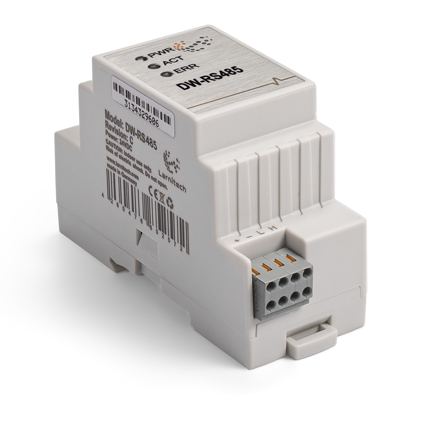
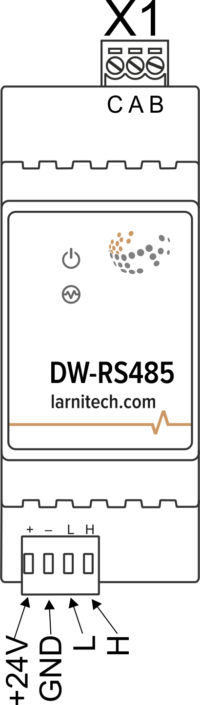
Overview
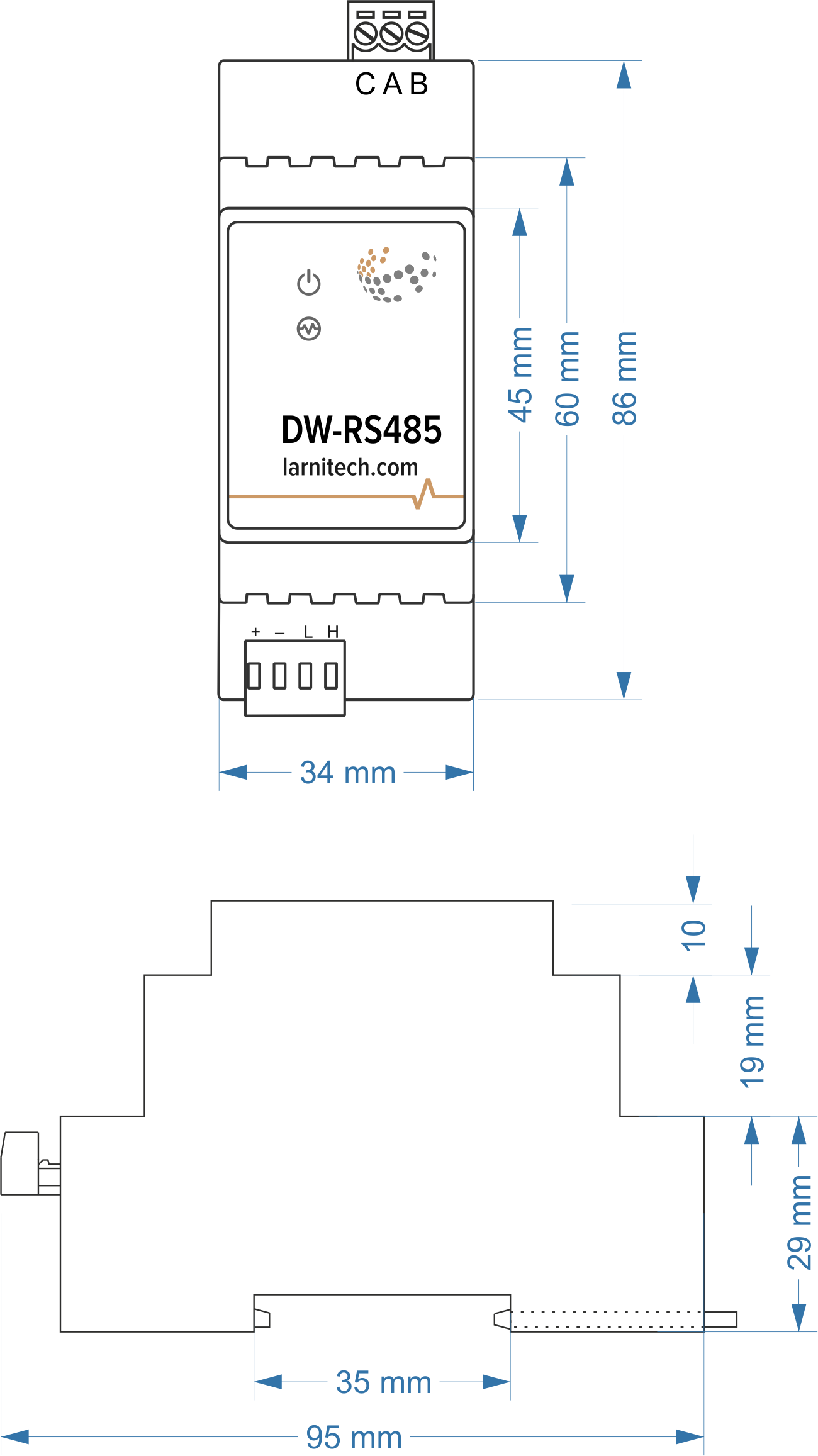
Module dimensions
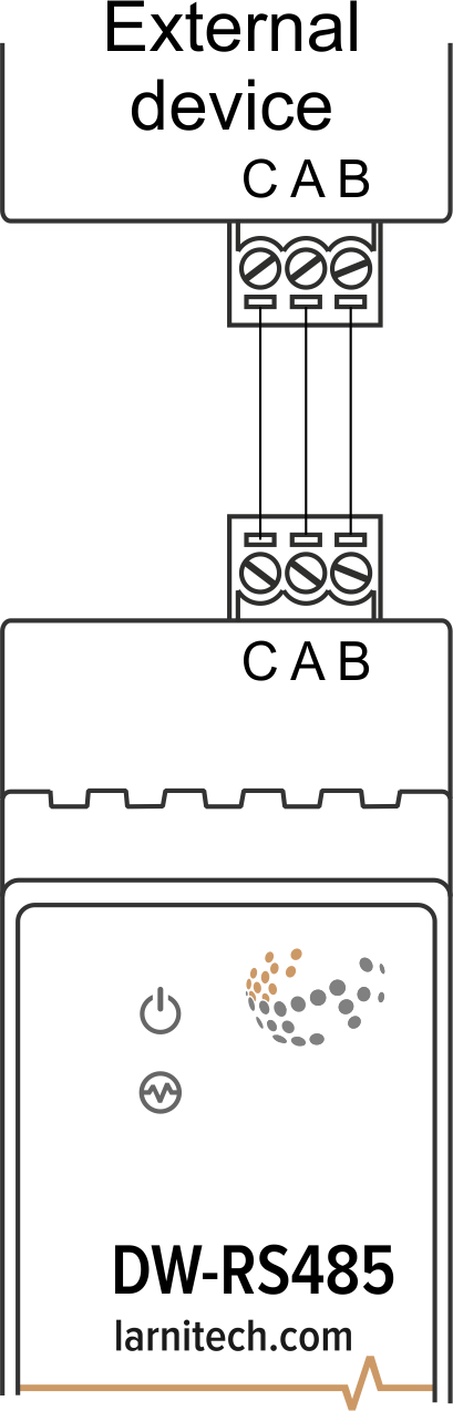
Example of connection
Module parameters
| Parameter name | Value |
|---|---|
| RS485 ports qty | 1 |
| Power supply | 11.5 … 27.5 V DC from CAN |
| Max current(24V) | 40 mA |
| Data transfer speed | 1200-115200 b/s |
| Bus type | CAN (4-wire) |
| Equipment installation type | DIN rail (EN 60715) |
| Case material | ABS |
| Protection | IP40 |
| Temperature range | -10 … +50 °C |
| Size | 2U, 36x97x58 mm |
| Weight | 130g |
Indication of module operation
Bootloader
| Indicator | Status | Description |
|---|---|---|
| Device in bootloader | ||
| Downloading firmware | ||
| Flashing firmware |
Firmware
| Indicator | Status | Description |
|---|---|---|
| Identification | ||
| Operational mode | ||
Error | ||
| Lost connection to server | ||
| Lost connection to AC | ||
| RTC error | ||
Activity | ||
| Transmitting data | ||
| Receiving data |
Module installation and connection procedure
- Install the module in the switchboard on the DIN rail and fix it with the special latch on the module base.
- Connect the X1 connector.
- Connect the CAN connector.
- Configure the module using LT setup.
- Check all equipment for proper operation.
Module shut-off and deinstallation procedure
- Disconnect the CAN connector.
- Disconnect the X1 connector.
- Remove the module from the DIN rail, releasing the latch at the bottom of the module base.
HW settings
| Name | Type, range | SUBID | Default | Description |
|---|---|---|---|---|
| cfg | string | 98 | 9600/8N1 | cfg='SPEED/BPS', where
Example: 1hw="cfg='9600/8N1'"
|
| [Protocol] | string | 98 | — | Protocol setting is described by protocol parameter. The following
protocols are supported:
Example: 1hw="cfg='9600/8N1' modbus"
|
| echo | on; off | 98 | 'off' | For settings check out and testing echo parameter can be used. Module
echo-reply can be turned on or off with the help of this parameter.Echo parameter value:
Example: 1hw="cfg='9600/8N1' echo='off'"
|
| term | integer 0-1 | 98 | '0' | Turning on built in RS485 bus 120Ω terminator
Example: 1hw="cfg='9600/8N1' term=1"
|