DW-SW16
Jump to navigation
Jump to search
| DW-SW16.C | |||||||||
|---|---|---|---|---|---|---|---|---|---|
 | |||||||||
| |||||||||
16-CHANNEL ADAPTER FOR BUTTONS
This module can support up to 15 buttons/reed switches or 8 LED buttons.
Features
- Up to 15 buttons/reed switches
- Up to 8 LED buttons
- Supports single/double/triple/long click.
Up to 4 different actions for each button - Line noise protection
CAUTION! All work related to the installation, connection, setting up, service and support must be carried out by qualified personnel with sufficient skills and experience in working with electrical equipment. To avoid the risk of fire, electric shock, damage to the system and/or personal injury, the system installation and assembly must be performed in accordance with the instructions listed below:
- all connectivity work must be carried out with the power turned OFF;
- use appropriate tools and personal protection against electric shock;
- do not use damaged cables, wires and connectors;
- avoid folding the cables and wires;
- do not apply excessive force to the wires by kinking or pressing them too hard: the inner conductors of the cables and wires may get stripped or damaged;
- do not use the power socket with poor contacts to connect;
- do not exceed the load limit parameters specified in the manual;
- the supply conductors wire section is subject to the specifications for current density limit, insulation type and wire material. Light section can result in cable overheating and fire.
When the power is on, NEVER:
- connect/disconnect the connectors;
- open modules and sensors.
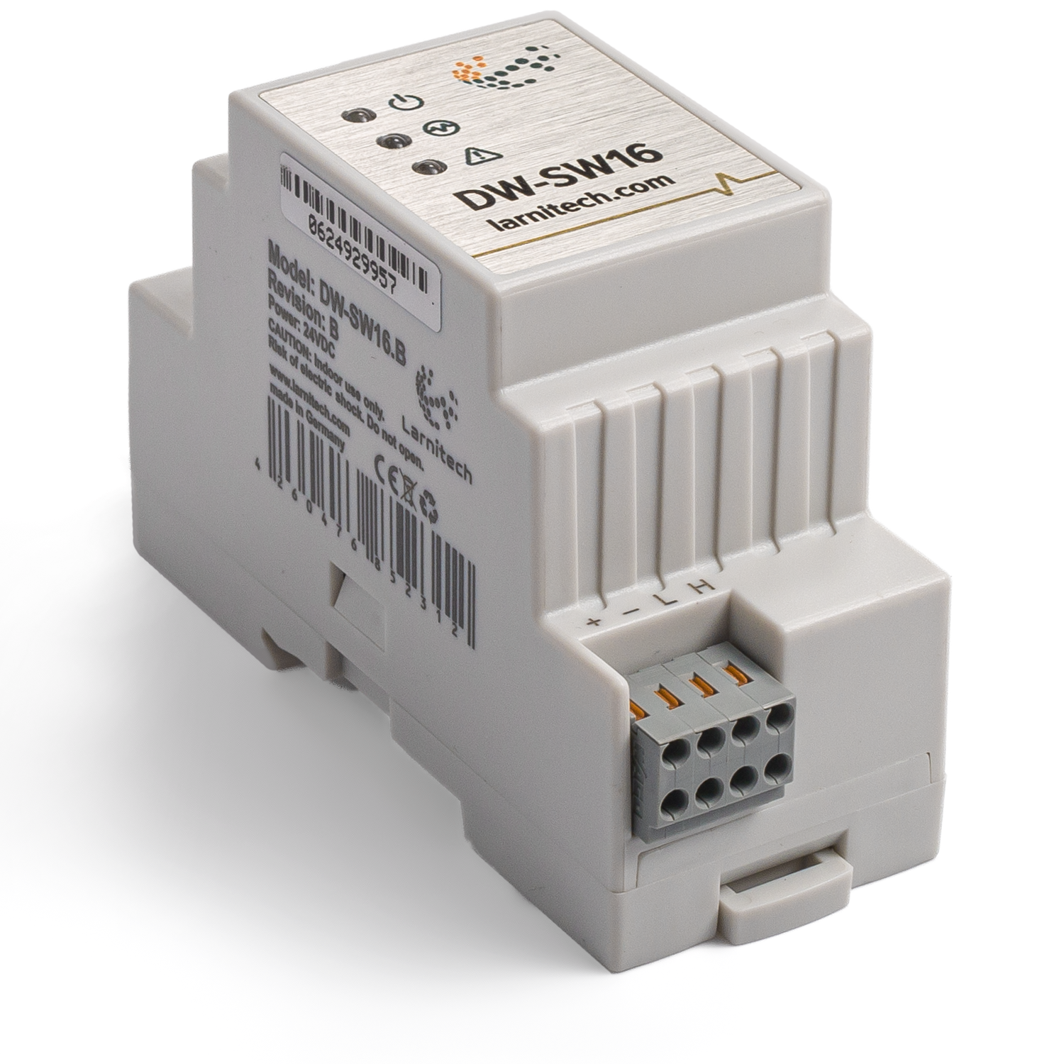
Overview
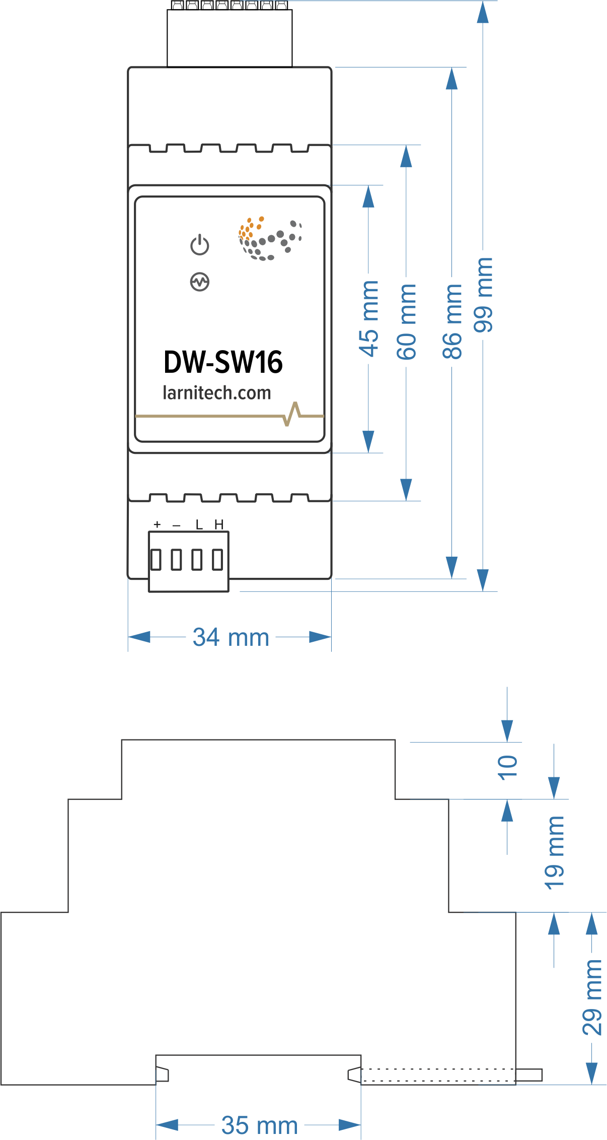
Module dimensions
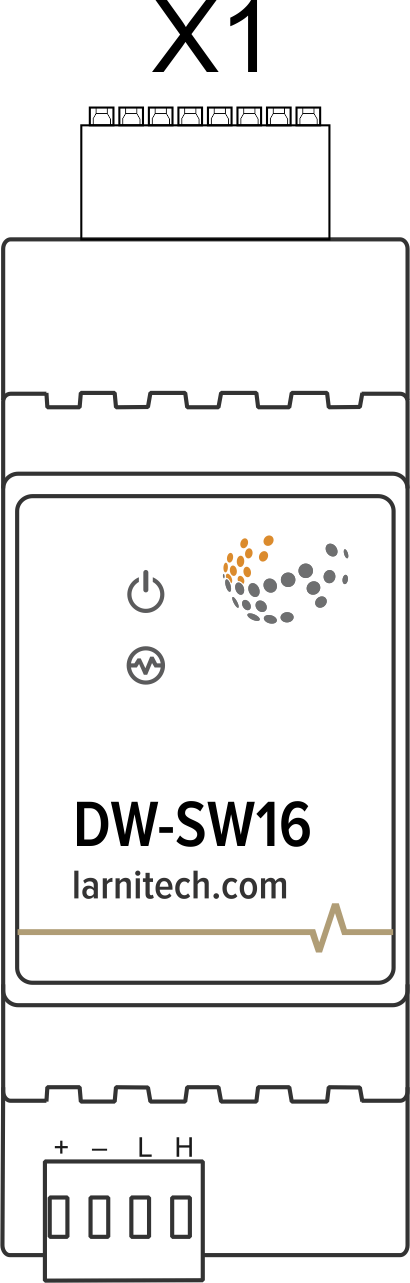
Connector
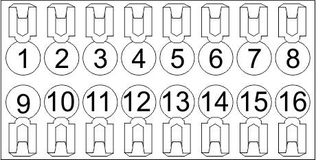
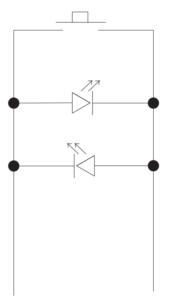
Led button scheme
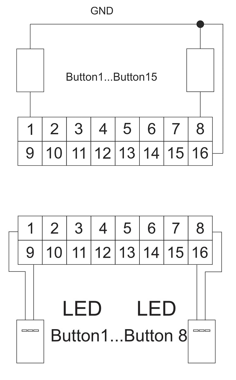
Connection of buttons/LED buttons
Module parameters
| Parameter name | Value |
|---|---|
| Input channels qty | 16 |
| Buttons | 15 |
| LED Buttons | 8 |
| Backlight voltage | 3V |
| Power supply | 11.5 … 27.5 V DC from CAN |
| Max current(24V) | 45 mA |
| Push-button/reed switches line recommended length | 30m |
| Bus type | CAN (4-wire) |
| Equipment installation type | DIN rail (EN 60715) |
| Case material | ABS |
| Protection | IP40 |
| Temperature range | -10 … +50 °C |
| Size | 2U, 36x102x58 mm |
| Weight | 75g |
Indication of module operation
Bootloader
| Indicator | Status | Description |
|---|---|---|
| Device in bootloader | ||
| Downloading firmware | ||
| Flashing firmware |
Firmware
| Indicator | Status | Description |
|---|---|---|
| Identification | ||
| Operational mode | ||
Error | ||
| Lost connection to server | ||
| RTC error | ||
Activity | ||
| Key pressed |
Module installation and connection procedure
- Install the module in the switchboard on the DIN rail and fix it with the special latch on the module base.
- Connect the X1 connector.
- Connect the CAN connector.
- Configure the module using LT setup.
- Check all equipment for proper operation.
Module shut-off and deinstallation procedure
- Disconnect the CAN connector.
- Disconnect the X1 connector.
- Remove the module from the DIN rail, releasing the latch at the bottom of the module base.
HW settings
| Name | Type, range | SUBID | Default | Description |
|---|---|---|---|---|
| in | char[16] | 98 | 'BBBBBBBBGGGGGGGG' | Each char is responsible for the type of a particular channel
Example: in='DEHHHHBB- -CCSSSG' |
 1<item addr="441:11" cfgid="55" name="Switch" type="switch" uniq_id="4628"/>
 2<item addr="441:12" cfgid="55" name="Switch" type="switch" uniq_id="4629"/>
 3<item addr="441:13" cfgid="55" name="Switch" type="switch" uniq_id="4630"/>
 4<item addr="441:14" cfgid="55" name="Switch" type="switch" uniq_id="4631"/>
 5<item addr="441:15" cfgid="55" name="Switch" type="switch" uniq_id="4632"/>
 6<item addr="441:16" cfgid="55" name="Switch" type="switch" uniq_id="4633"/>
 7<item addr="441:17" cfgid="55" name="Switch" type="switch" uniq_id="4634"/>
 8<item addr="441:18" cfgid="55" name="Door" type="door-sensor" uniq_id="4637"/>
 9<item addr="441:19" cfgid="55" name="Switch" type="switch" uniq_id="4638"/>
10<item addr="441:20" cfgid="55" name="Switch" type="switch" uniq_id="4639"/>
11<item addr="441:25" cfgid="55" name="Switch" type="switch" uniq_id="4640"/>
12<item addr="441:98" cfgid="55" hw="in='BBDDEESHBB----BG'" name="Temperature" system="yes" type="temperature-sensor" uniq_id="4636"/>