DW-SW16
Jump to navigation
Jump to search
| DW-SW16.C | |||||||||
|---|---|---|---|---|---|---|---|---|---|
 | |||||||||
| |||||||||
16-ТИ КАНАЛЬНЫЙ АДАПТЕР ДЛЯ КНОПОК/16-канальный модуль входов
Модуль может поддерживать до 15-ти кнопок/герконов или до 8-ми светодиодных кнопок
Функции
- Поддержка до 15-ти кнопок/герконов
- Поддержка до 8-ми светодиодных кнопок
- Поддержка одиночного/двойного/тройного/многократного нажатия.
Поддержка до 4-х различных действий для каждой кнопки - Линейная защита от помех
ВНИМАНИЕ! Все работы, связанные с установкой, подключением, настройкой, обслуживанием и поддержкой оборудования, должны выполняться только квалифицированным персоналом, обладающим достаточными навыками и опытом работы с электрооборудованием! Во избежание риска возгорания, поражения электрическим током, повреждения системы и/или травм, установка и сборка системы должны выполняться в соответствии с указаниями, перечисленными ниже:
- все работы по подключению должны выполняться при выключенном питании;
- необходимо использовать соответствующие инструменты и средства индивидуальной защиты от поражения электрическим током;
- запрещается использовать поврежденные кабели, провода и разъемы;
- избегайте перегиба проводов и кабелей;
- не прилагайте чрезмерных усилий к проводам путем их перегиба или слишком сильного сжатия: внутренние проводники кабелей и проводов могут быть оголены или повреждены;
- не используйте для подключения разъемы с плохими контактами;
- не превышайте параметры предельной нагрузки, указанные в инструкции;
- сечение питающих проводов зависит от требований к пределу плотности тока, типу изоляции и материалу проводов. Недостаточное сечение провода может привести к перегреву кабеля и возгоранию.
Когда питание включено, НИКОГДА:
- не подключайте/отключайте разъемы;
- не открывайте модули и датчики.
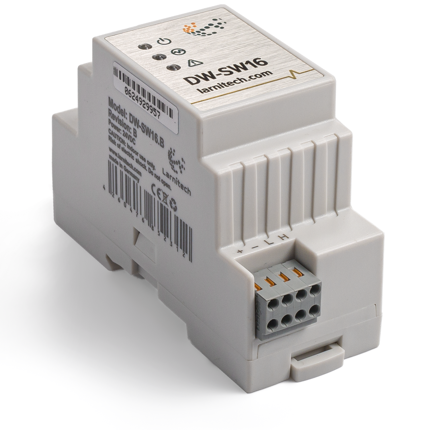
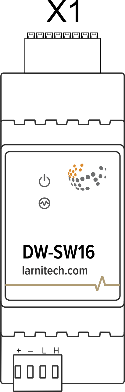
Изображение модуля
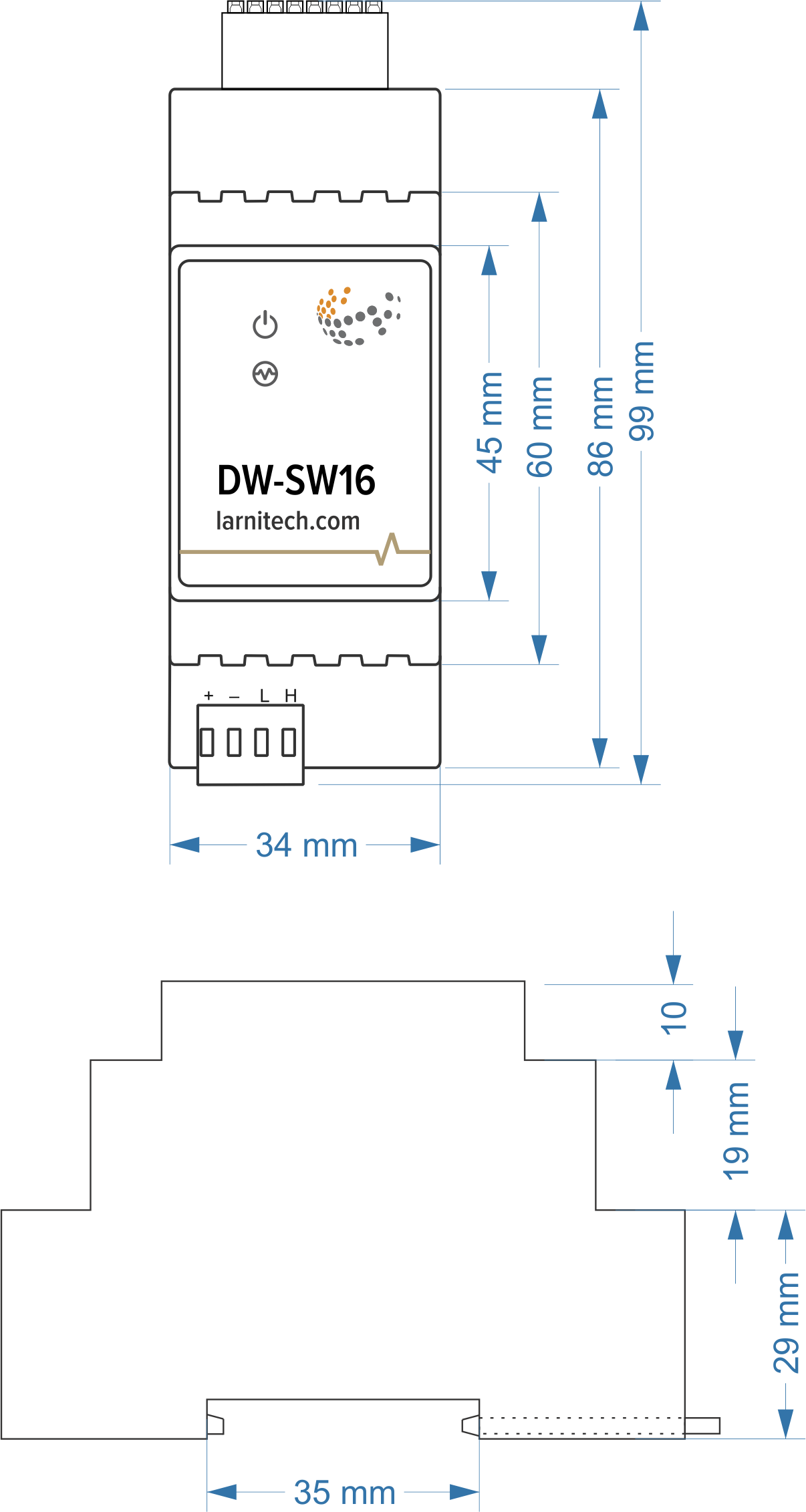
Размеры модуля
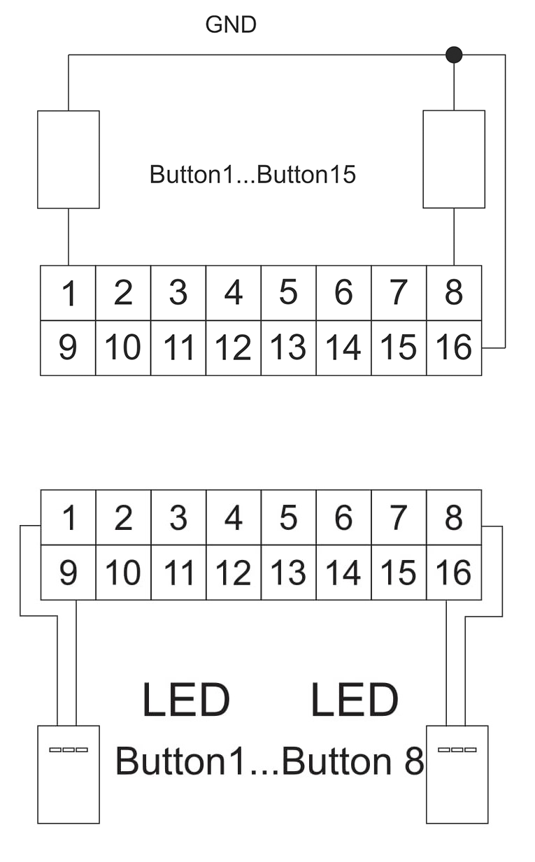
Разъемы
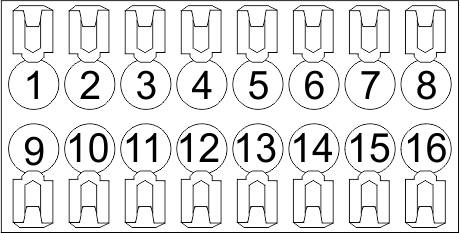
Схема подключения светодиодных кнопок
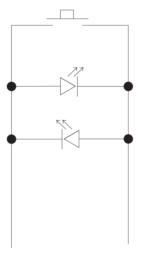
Подключение кнопок/светодиодных кнопок
Параметры модуля
| Parameter name | Value |
|---|---|
| Input channels qty | 16 |
| Buttons | 15 |
| LED Buttons | 8 |
| Backlight voltage | 3V |
| Power supply | 11.5 … 27.5 V DC from CAN |
| Max current(24V) | 45 mA |
| Push-button/reed switches line recommended length | 30m |
| Bus type | CAN (4-wire) |
| Equipment installation type | DIN rail (EN 60715) |
| Case material | ABS |
| Protection | IP40 |
| Temperature range | -10 … +50 °C |
| Size | 2U, 36x102x58 mm |
| Weight | 75g |
Индикация работы модуля
Загрузчик
| Indicator | Status | Description |
|---|---|---|
| Device in bootloader | ||
| Downloading firmware | ||
| Flashing firmware |
Прошивка
| Indicator | Status | Description |
|---|---|---|
| Identification | ||
| Operational mode | ||
Error | ||
| Lost connection to server | ||
| RTC error | ||
Activity | ||
| Key pressed |
Module installation and connection procedure
- Install the module in the switchboard on the DIN rail and fix it with the special latch on the module base.
- Connect the X1 connector.
- Connect the CAN connector.
- Configure the module using LT setup.
- Check all equipment for proper operation.
Module shut-off and deinstallation procedure
- Disconnect the CAN connector.
- Disconnect the X1 connector.
- Remove the module from the DIN rail, releasing the latch at the bottom of the module base.
HW settings
| Name | Type, range | SUBID | Default | Description |
|---|---|---|---|---|
| in | char[16] | 98 | 'BBBBBBBBGGGGGGGG' | Each char is responsible for the type of a particular channel
Example: in='DEHHHHBB- -CCSSSG' |
 1<item addr="441:11" cfgid="55" name="Switch" type="switch" uniq_id="4628"/>
 2<item addr="441:12" cfgid="55" name="Switch" type="switch" uniq_id="4629"/>
 3<item addr="441:13" cfgid="55" name="Switch" type="switch" uniq_id="4630"/>
 4<item addr="441:14" cfgid="55" name="Switch" type="switch" uniq_id="4631"/>
 5<item addr="441:15" cfgid="55" name="Switch" type="switch" uniq_id="4632"/>
 6<item addr="441:16" cfgid="55" name="Switch" type="switch" uniq_id="4633"/>
 7<item addr="441:17" cfgid="55" name="Switch" type="switch" uniq_id="4634"/>
 8<item addr="441:18" cfgid="55" name="Door" type="door-sensor" uniq_id="4637"/>
 9<item addr="441:19" cfgid="55" name="Switch" type="switch" uniq_id="4638"/>
10<item addr="441:20" cfgid="55" name="Switch" type="switch" uniq_id="4639"/>
11<item addr="441:25" cfgid="55" name="Switch" type="switch" uniq_id="4640"/>
12<item addr="441:98" cfgid="55" hw="in='BBDDEESHBB----BG'" name="Temperature" system="yes" type="temperature-sensor" uniq_id="4636"/>