Difference between revisions of "DW-UART/ru"
Jump to navigation
Jump to search
(Created page with "==Изображение модуля==") |
(Created page with "==Размеры модуля==") |
||
| Line 33: | Line 33: | ||
[[File:UARTC VIEW.png|300px]] | [[File:UARTC VIEW.png|300px]] | ||
| − | == | + | ==Размеры модуля== |
[[File:UARTC DIM.png|500px]] | [[File:UARTC DIM.png|500px]] | ||
Revision as of 13:33, 7 January 2022
| DW-UART.C | |||||||
|---|---|---|---|---|---|---|---|
 | |||||||
| |||||||
АДАПТЕР ПОСЛЕДОВАТЕЛЬНОГО ИНТЕРФЕЙСА
Модуль предназначен для сопряжения интерфейсов между устройствами с интерфейсом UART (уровней TTL) и системой Умный дом.
ВНИМАНИЕ! Все работы, связанные с установкой, подключением, настройкой, обслуживанием и поддержкой оборудования, должны выполняться только квалифицированным персоналом, обладающим достаточными навыками и опытом работы с электрооборудованием! Во избежание риска возгорания, поражения электрическим током, повреждения системы и/или травм, установка и сборка системы должны выполняться в соответствии с указаниями, перечисленными ниже:
- все работы по подключению должны выполняться при выключенном питании;
- необходимо использовать соответствующие инструменты и средства индивидуальной защиты от поражения электрическим током;
- запрещается использовать поврежденные кабели, провода и разъемы;
- избегайте перегиба проводов и кабелей;
- не прилагайте чрезмерных усилий к проводам путем их перегиба или слишком сильного сжатия: внутренние проводники кабелей и проводов могут быть оголены или повреждены;
- не используйте для подключения разъемы с плохими контактами;
- не превышайте параметры предельной нагрузки, указанные в инструкции;
- сечение питающих проводов зависит от требований к пределу плотности тока, типу изоляции и материалу проводов. Недостаточное сечение провода может привести к перегреву кабеля и возгоранию.
Когда питание включено, НИКОГДА:
- не подключайте/отключайте разъемы;
- не открывайте модули и датчики.
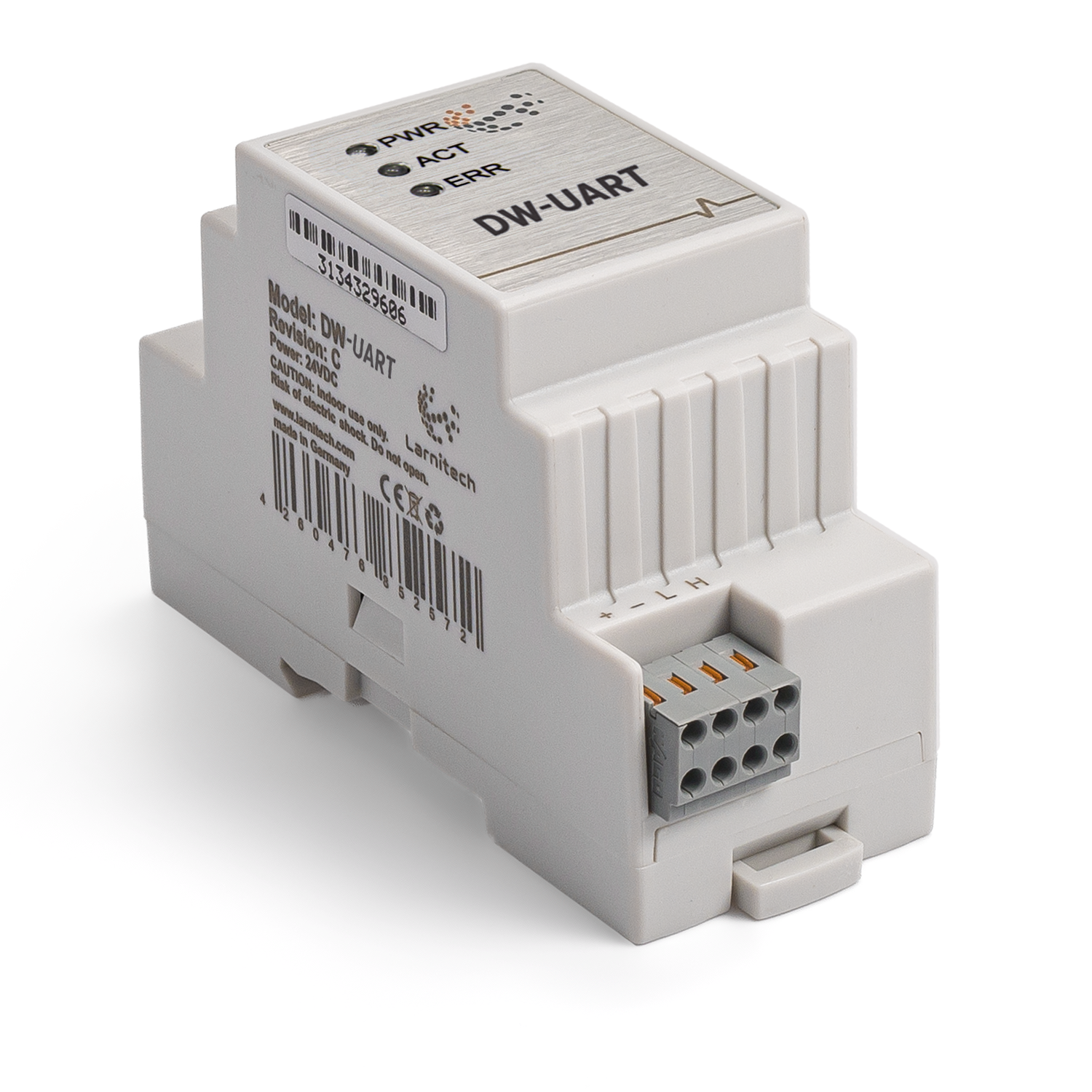
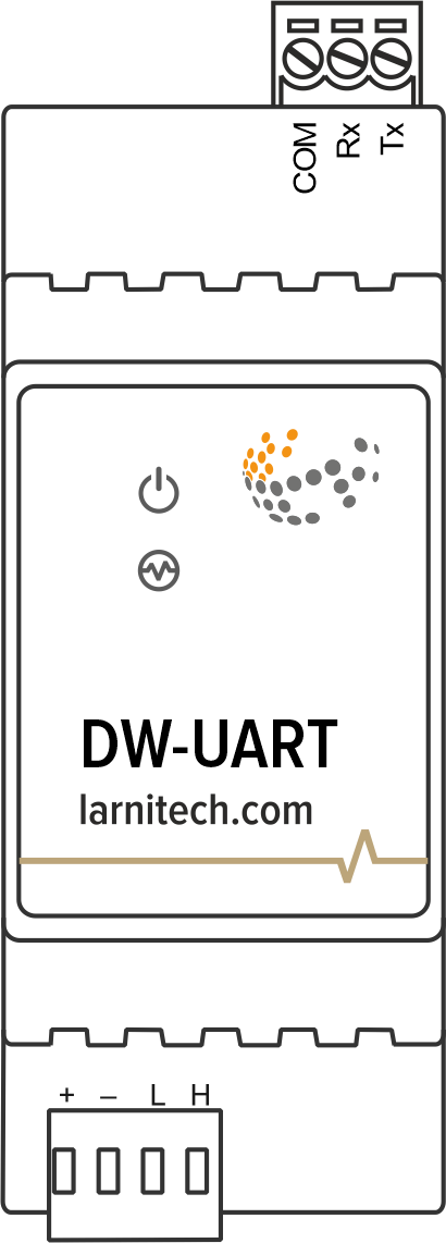
Изображение модуля
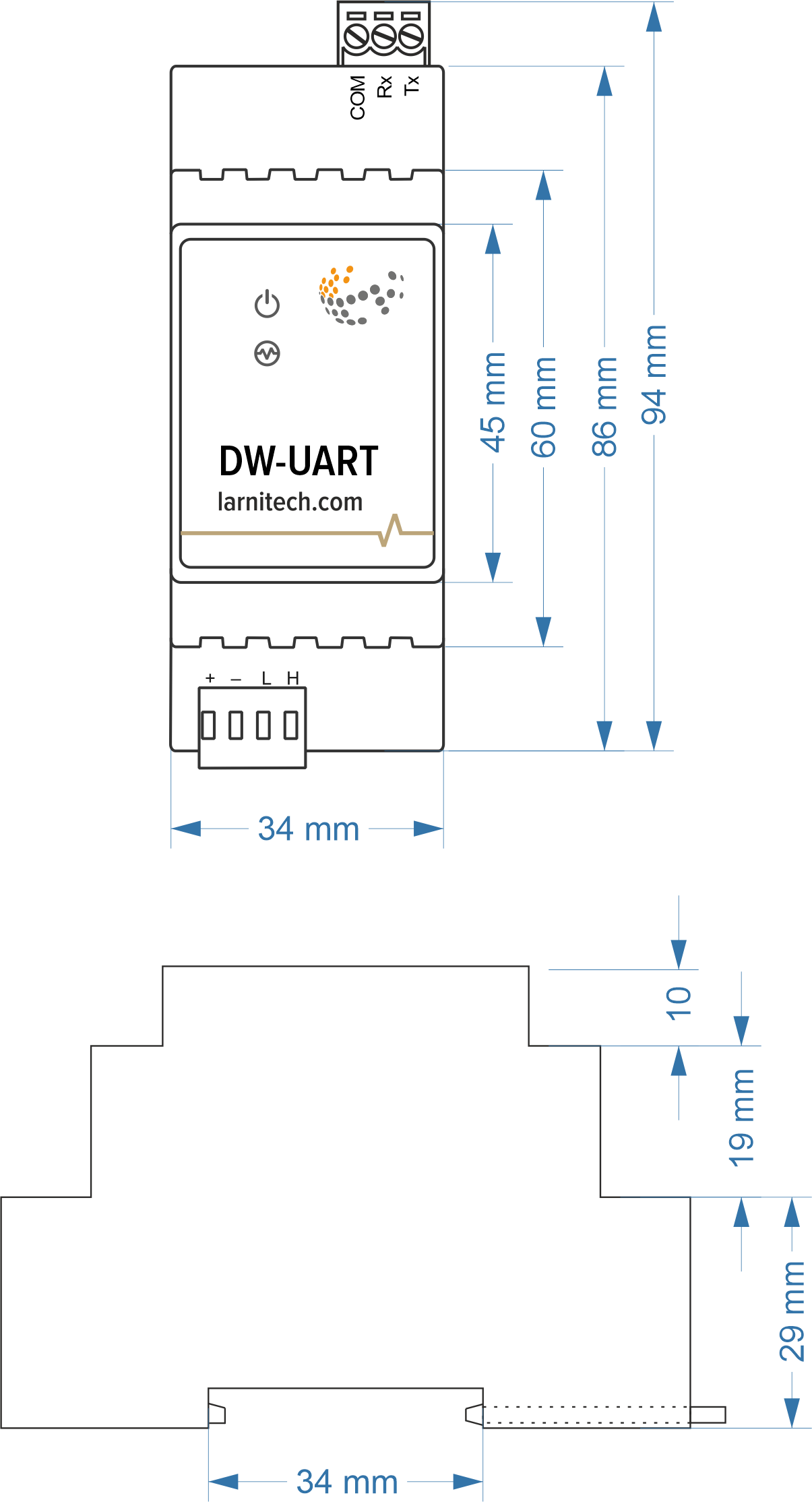
Размеры модуля
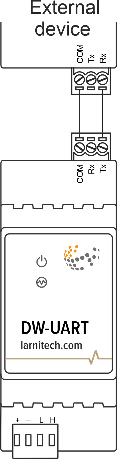
Example of connection
Module parameters
| Parameter name | Value |
|---|---|
| UART ports qty | 1 |
| Power supply | 11.5 … 27.5 V DC from CAN |
| Max current(24V) | 40 mA |
| Data transfer speed | 1200-115200 b/s |
| Bus type | CAN (4-wire) |
| Equipment installation type | DIN rail (EN 60715) |
| Case material | ABS |
| Protection | IP40 |
| Temperature range | -10 … +50 °C |
| Size | 2U, 36x97x58 mm |
| Weight | 130g |
Indication of module operation
| Indicator | Status | Description |
|---|---|---|
| Power | Power | |
| Power not available | ||
| Activity | Data communication | |
| Data communication not available | ||
| Error | No errors | |
| Overheating | ||
| The data has not been transferred via the CAN bus for at least 5 minutes. |
Module installation and connection procedure
- Install the module in the switchboard on the DIN rail and fix it with the special latch on the module base.
- Connect the X1 connector.
- Connect the CAN connector.
- Configure the module using LT setup.
- Check all equipment for proper operation.
Module shut-off and deinstallation procedure
- Disconnect the CAN connector.
- Disconnect the X1 connector.
- Remove the module from the DIN rail, releasing the latch at the bottom of the module base.
HW settings
| Name | Type, range | SUBID | Default | Description |
|---|---|---|---|---|
| cfg | string | 98 | 9600/8N1 | cfg='SPEED/BPS', where
Example: 1hw="cfg='9600/8N1'"
|
| [Protocol] | string | 98 | — | Protocol setting is described by protocol parameter. The following
protocols are supported:
Example: 1hw="cfg='9600/8N1' modbus"
|
| echo | on; off | 98 | 'off' | For settings check out and testing echo parameter can be used. Module
echo-reply can be turned on or off with the help of this parameter.Echo parameter value:
Example: 1hw="cfg='9600/8N1' echo='off'"
|