Difference between revisions of "DW-WL02.A"
Jump to navigation
Jump to search
| (One intermediate revision by the same user not shown) | |||
| Line 58: | Line 58: | ||
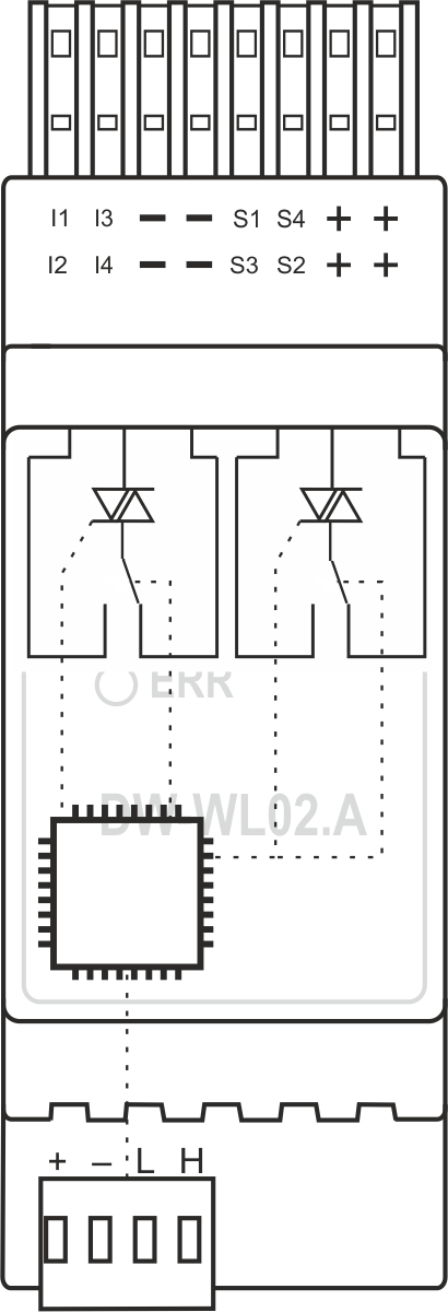
==Internal layout== | ==Internal layout== | ||
| − | [[File:WL02A IL.png| | + | [[File:WL02A IL.png|300px]] |
| − | |||
==Module parameters== | ==Module parameters== | ||
| Line 75: | Line 74: | ||
| sensmaxvcccur = 70 mA | | sensmaxvcccur = 70 mA | ||
| rinmaxcur = 3 mA | | rinmaxcur = 3 mA | ||
| − | | | + | | smaxlen = 30m |
| bustype = CAN (4-wire) | | bustype = CAN (4-wire) | ||
| instalation = DIN-rail (EN 60715) | | instalation = DIN-rail (EN 60715) | ||
Latest revision as of 14:49, 10 August 2021
| DW-WL02.A | |||||||
|---|---|---|---|---|---|---|---|
 | |||||||
| |||||||
| |||||||
WATER LEAKAGE PROTECTION MODULE
The module supports the connection of 2 valves of water supply shutoff and 4 leakage sensors.
Features
- Supports 1p/2p valves
- Valve feedback reed switch
- 4 leakage zones (up to 8 sensors)
- Sensor detection and diagnostics
CAUTION! All work related to the installation, connection, setting up, service and support must be carried out by qualified personnel with sufficient skills and experience in working with electrical equipment. To avoid the risk of fire, electric shock, damage to the system and/or personal injury, the system installation and assembly must be performed in accordance with the instructions listed below:
- all connectivity work must be carried out with the power turned OFF;
- use appropriate tools and personal protection against electric shock;
- do not use damaged cables, wires and connectors;
- avoid folding the cables and wires;
- do not apply excessive force to the wires by kinking or pressing them too hard: the inner conductors of the cables and wires may get stripped or damaged;
- do not use the power socket with poor contacts to connect;
- do not exceed the load limit parameters specified in the manual;
- the supply conductors wire section is subject to the specifications for current density limit, insulation type and wire material. Light section can result in cable overheating and fire.
When the power is on, NEVER:
- connect/disconnect the connectors;
- open modules and sensors.
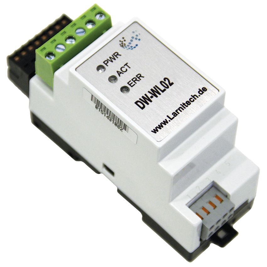
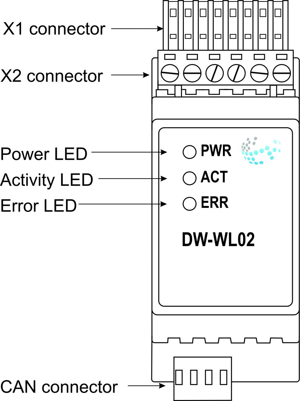
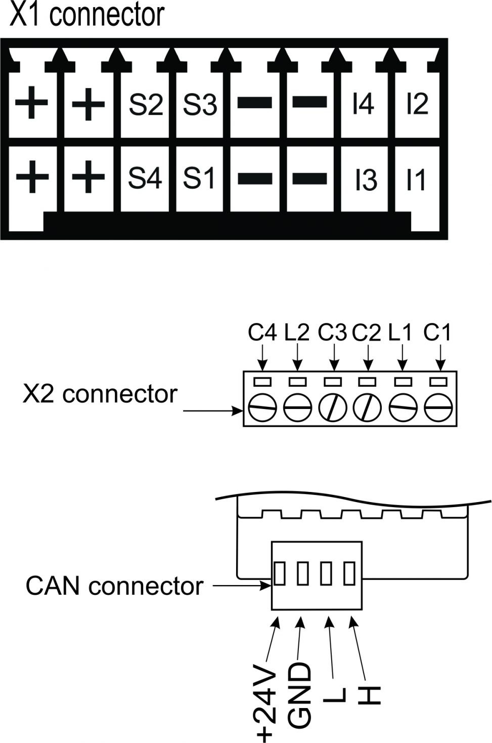
Overview
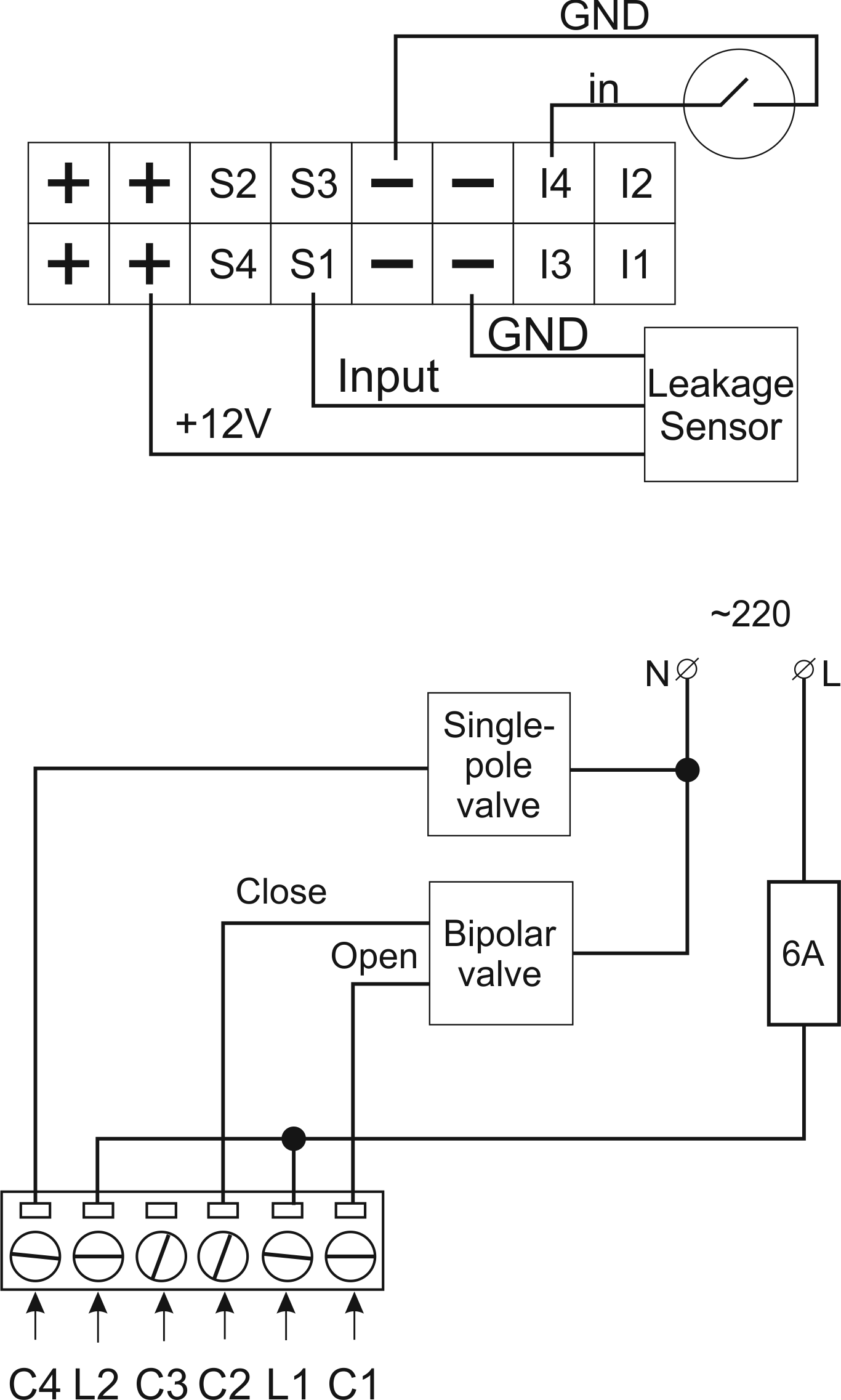
Example of connection
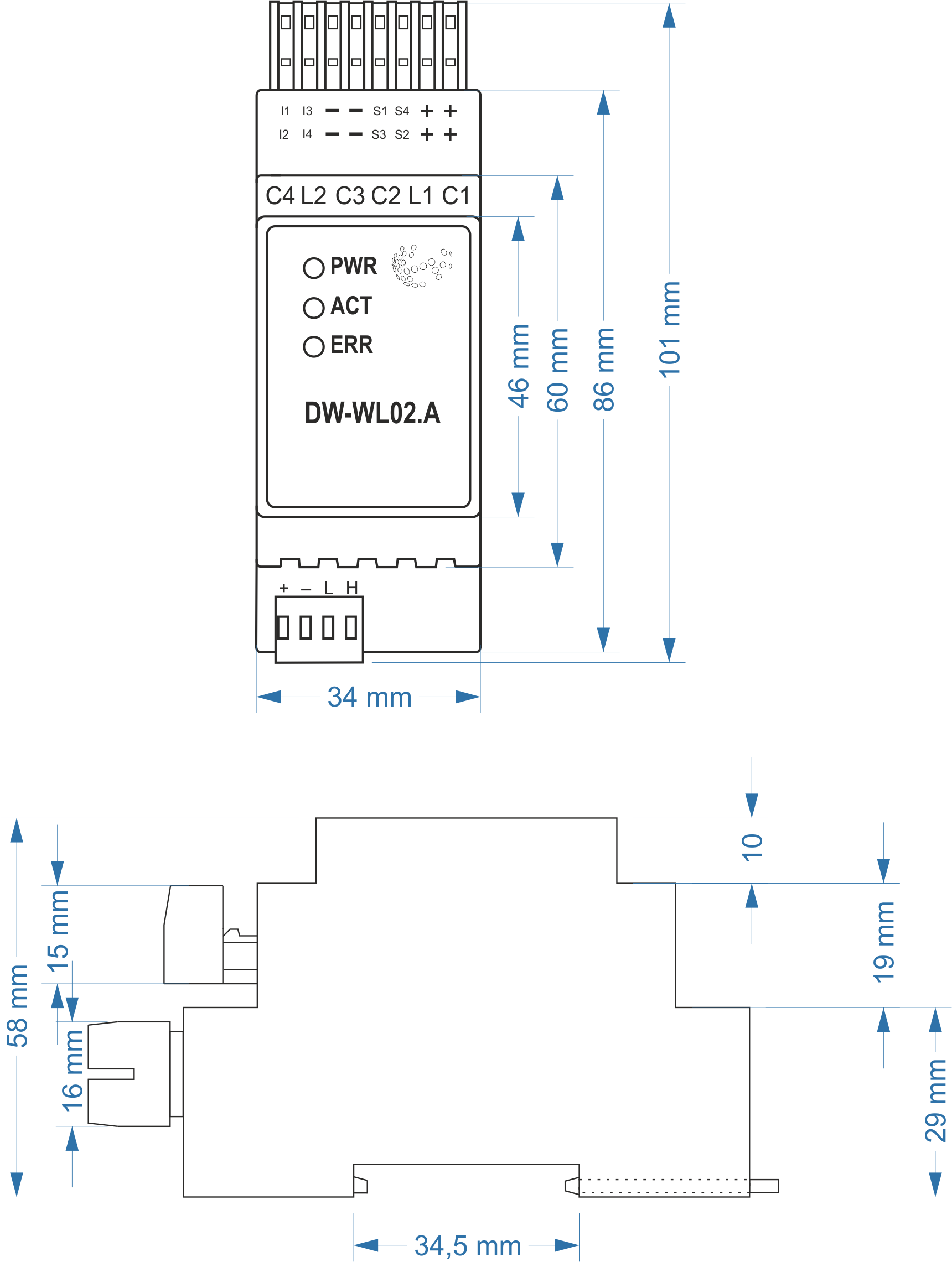
Module dimensions
Internal layout
Module parameters
| Parameter name | Value |
|---|---|
| Number of sensor inputs | 4 |
| Number of dry contact inputs | 4 |
| Output channels qty | 2 |
| Input voltage | 100-250 V AC |
| Current type | AC |
| Max load per channel | 2A |
| Power supply | 11.5 … 27.5 V DC from CAN |
| Max current(24V) | 60 mA |
| Sensors VCC output | 8..12 V |
| Sensors max VCC current | 70 mA |
| R1-R2 inputs max current | 3 mA |
| Sensors line max length | 30m |
| Bus type | CAN (4-wire) |
| Equipment installation type | DIN rail (EN 60715) |
| Case material | ABS |
| Protection | IP40 |
| Temperature range | -10 … +50 °C |
| Size | 2U, 35x102x58 mm |
| Weight | 100 g |
Indication of module operation
| Indicator | Status | Description |
|---|---|---|
| Power | Power | |
| Power not available | ||
| Activity | Data communication | |
| Data communication not available | ||
| Error | No errors | |
| Overheating | ||
| The data has not been transferred via the CAN bus for at least 5 minutes. |
Module installation and connection procedure
- Install the module in the switchboard on the DIN rail and fix it with the special latch on the module base.
- Connect the CAN connector.
- Connect the channels.
- Configure the module using LT setup.
- Apply power to the load.
- Check all equipment for proper operation.
Module shut-off and deinstallation procedure
- Disconnect the power from the load.
- Disconnect the channels.
- Disconnect the CAN connector.
- Remove the module from the DIN rail, releasing the latch at the bottom of the module base.
HW settings
| Name | Type, range | SUBID | Default | Description |
|---|---|---|---|---|
| runtime | integer 0-100 | 1-4 | 15 | runtime is the open/close time in seconds, is used for jalousie, gate, valve(2 pole); Example: runtime=15 |
| hold | integer 0-10000 | 1-4 | 500 | hold is the bridging time in miliseconds, is used for gate and jalousie (by default hold is the same as runtime), lock; Example: hold=3500 |
| def | string 'ON' | 1-4 | 'OFF' | Def is the element status is set after restart, is used for lamp, heating, valve(1 pole); Example: def='ON' |
| stop | Char 'R' | 1-3 | – | (for 2-pole gate and blinds) If it is declared then by Stop command during the motion, the same impulse appears as it was at the beginning of the motion. Pole, an which the stop-impules is formed, is defined by the parameter Stop value. If it is 'r' or 'R' then stop-impulse is produced on the opposite to the start-impulse pole. If any other value is delcared (e.g., 'd' ) then the stop-impulse is on the same pole. If a Runtime passed after the beginning of the motion then the stop-impulse is not formed. Example: stop='r' |
| out | char[4] | 98 | 'V-V-' | Each char is responsible for the type of a particular channel
Example: out='V-V-' |
| leak | char[4] | 98 | 'LLLL' | Each char is responsible for the type of a particular channel
|
| in | char[4] | 98 | 'KKKK' | Each char is responsible for the type of a particular channel
Example: in='HHKK' |
 1<item addr="500:1" cfgid="53" hw="runtime=30" name="Valve" type="valve" uniq_id="4105"/>
 2<item addr="500:3" cfgid="53" name="Jalousie" sub-type="120" type="jalousie" uniq_id="4117"/>
 3<item addr="500:11" cfgid="53" name="Leak" type="leak-sensor" uniq_id="4107"/>
 4<item addr="500:12" cfgid="53" name="Leak" type="leak-sensor" uniq_id="4108"/>
 5<item addr="500:13" cfgid="53" name="Leak" type="leak-sensor" uniq_id="4109"/>
 6<item addr="500:14" cfgid="53" name="Leak" type="leak-sensor" uniq_id="4110"/>
 7<item addr="500:21" cfgid="53" name="Door" type="door-sensor" uniq_id="4111"/>
 8<item addr="500:22" cfgid="53" name="Door" type="door-sensor" uniq_id="4112"/>
 9<item addr="500:23" cfgid="53" name="Door" type="door-sensor" uniq_id="4113"/>
10<item addr="500:24" cfgid="53" name="Door" type="door-sensor" uniq_id="4114"/>
11<item addr="500:97" cfgid="53" name="Temperature" system="yes" type="temperature-sensor" uniq_id="4115"/>
12<item addr="500:98" cfgid="53" hw="leak='NNLL' in='HHKK' out='V-B-'" name="Temperature" system="yes" type="temperature-sensor" uniq_id="4116"/>