Difference between revisions of "Larnitech Smart Home System Architecture"
(Marked this version for translation) |
|||
| (2 intermediate revisions by 2 users not shown) | |||
| Line 1: | Line 1: | ||
| + | <languages/> | ||
| + | <translate> | ||
| + | <!--T:1--> | ||
<youtube width="400px">x2LUHX0zOgY</youtube> | <youtube width="400px">x2LUHX0zOgY</youtube> | ||
{| class="wikitable" | {| class="wikitable" | ||
| Line 11: | Line 14: | ||
|As can be seen from the table below, a Four-wire bus is used (two twisted pairs) with a maximum length of a eight hundred | |As can be seen from the table below, a Four-wire bus is used (two twisted pairs) with a maximum length of a eight hundred | ||
metres. A maximum of 50 devices can be connected to each CAN bus. | metres. A maximum of 50 devices can be connected to each CAN bus. | ||
| − | <br>[[file:Architecture3. | + | <br>[[file:Architecture3.jpg|700px]] |
|- | |- | ||
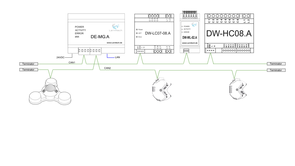
|The following diagram shows how modules can be connected to the system. In the drawing below a 7-channel | |The following diagram shows how modules can be connected to the system. In the drawing below a 7-channel | ||
| Line 19: | Line 22: | ||
|The second CAN bus has a four-in-one multi-sensor, a dimmer and a two-channel pattress box space actuator. In such | |The second CAN bus has a four-in-one multi-sensor, a dimmer and a two-channel pattress box space actuator. In such | ||
| + | <!--T:2--> | ||
a manner up to 100 devices can be connected to the main gateway. | a manner up to 100 devices can be connected to the main gateway. | ||
<br>[[file:Architecture5.png|700px]] | <br>[[file:Architecture5.png|700px]] | ||
| Line 70: | Line 74: | ||
<br>[[file:Architecture16.png|700px]] | <br>[[file:Architecture16.png|700px]] | ||
|} | |} | ||
| + | </translate> | ||
Latest revision as of 11:35, 13 January 2022
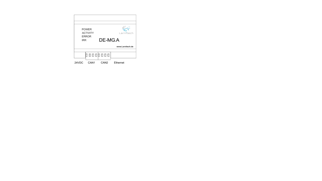
| The Main Gateway is the core device of the system. Its main task is to configure the system, and provide the logic for
its operation. It also keeps track of the sensors data and provides authorized access to the system. The Main Gateway is connected to the local network. It has 2 CAN bus ports.
|
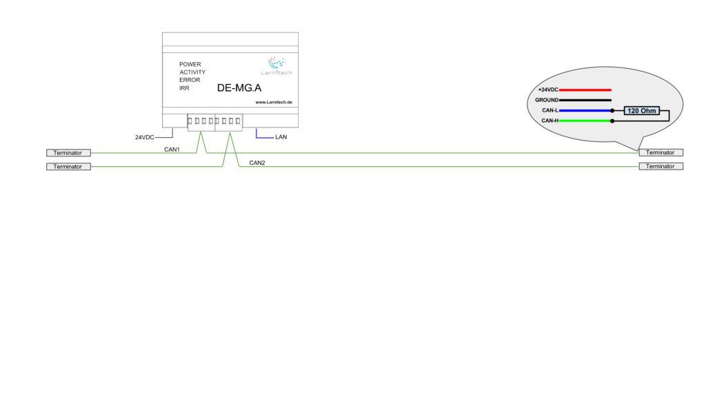
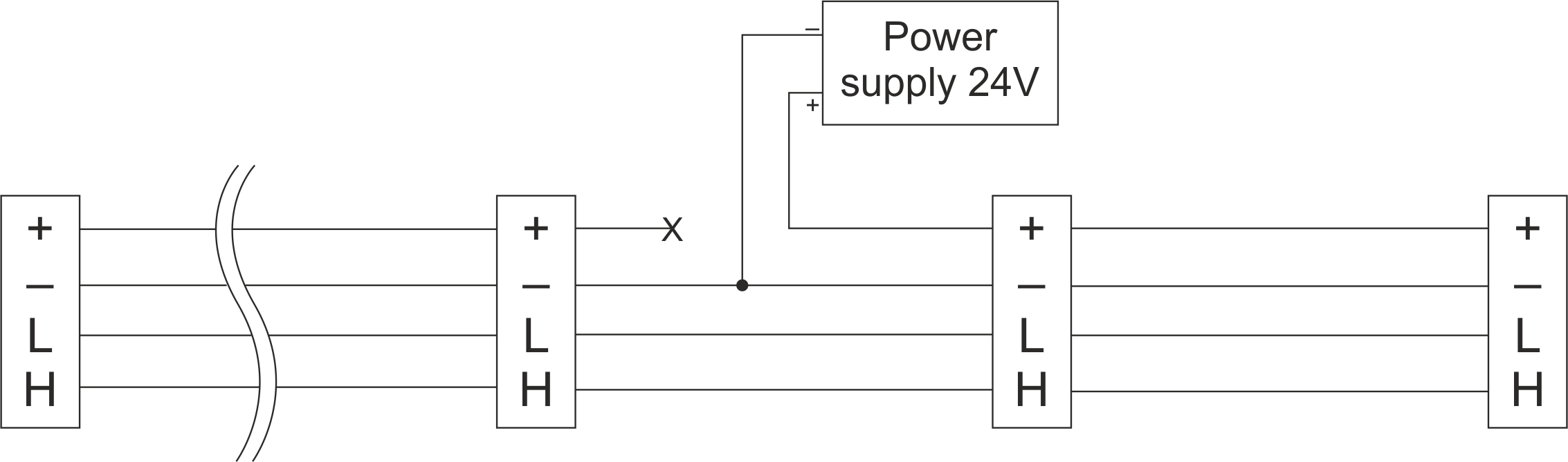
| The CAN bus is used to connect the sensors and actuators to the system. Terminators, 120 Ohm resistors, need to be
installed at the end of the CAN bus.
|
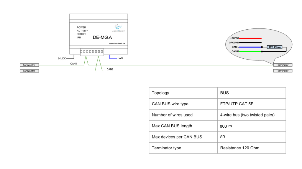
| As can be seen from the table below, a Four-wire bus is used (two twisted pairs) with a maximum length of a eight hundred
metres. A maximum of 50 devices can be connected to each CAN bus.
|
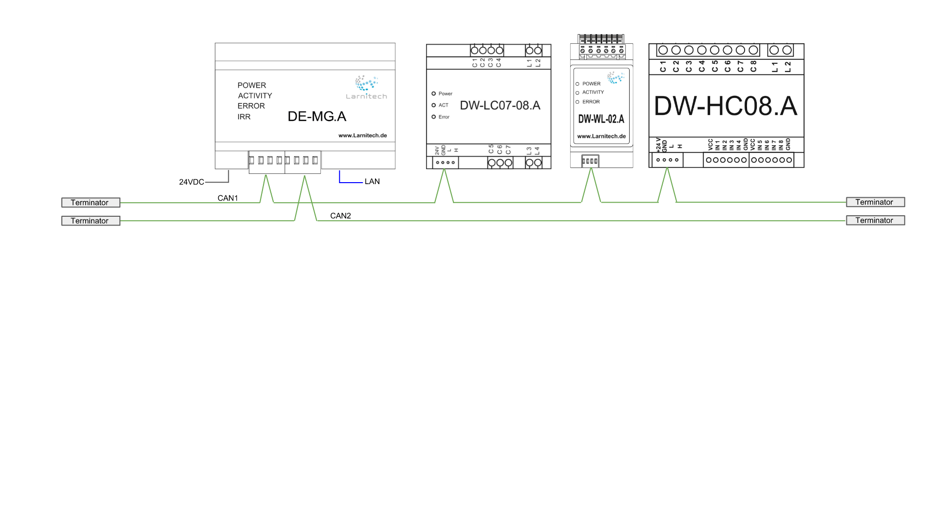
| The following diagram shows how modules can be connected to the system. In the drawing below a 7-channel
actuator, a leak control module and a heating control module have been connected to the first CAN bus.
|
| The second CAN bus has a four-in-one multi-sensor, a dimmer and a two-channel pattress box space actuator. In such
a manner up to 100 devices can be connected to the main gateway.
|
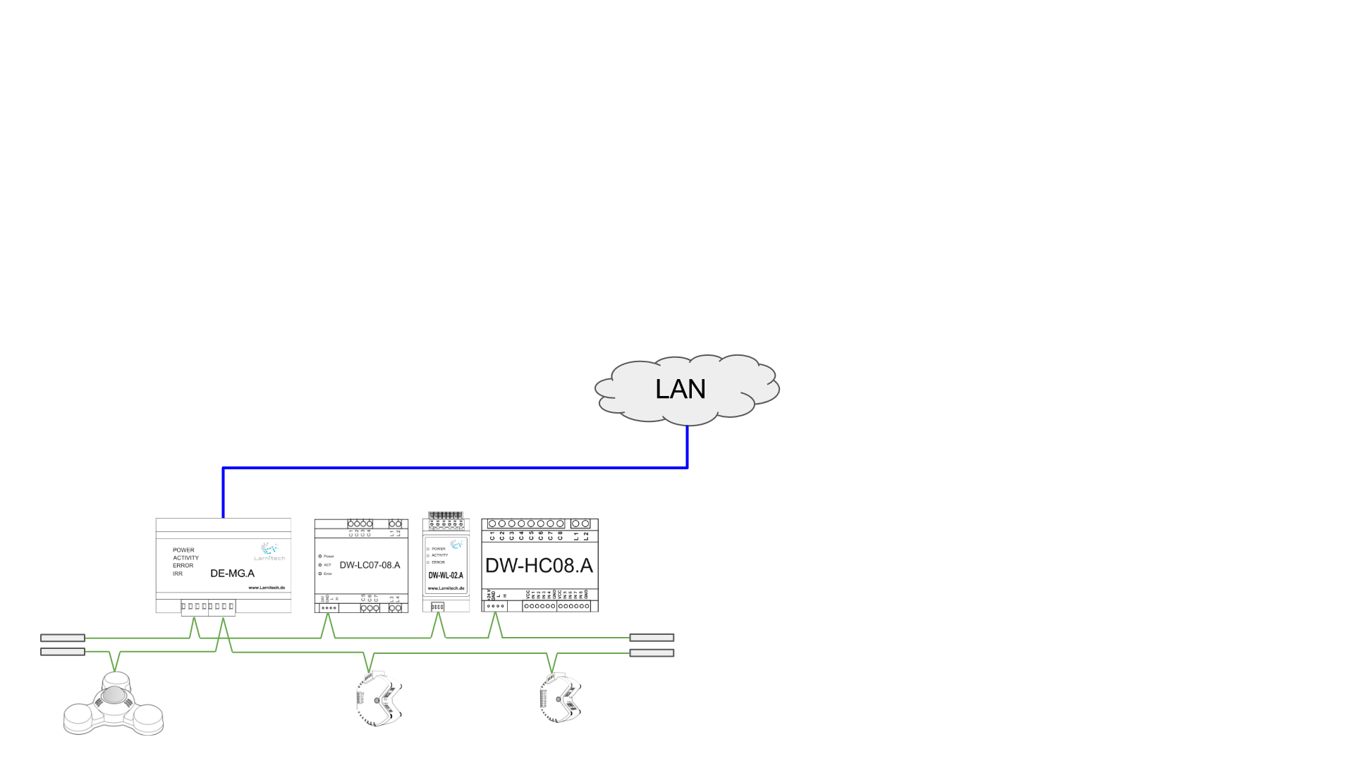
| In its turn, the main gateway is connected to the Local Area Network.
|
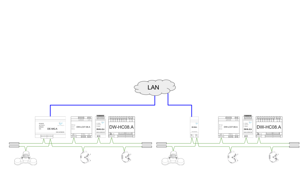
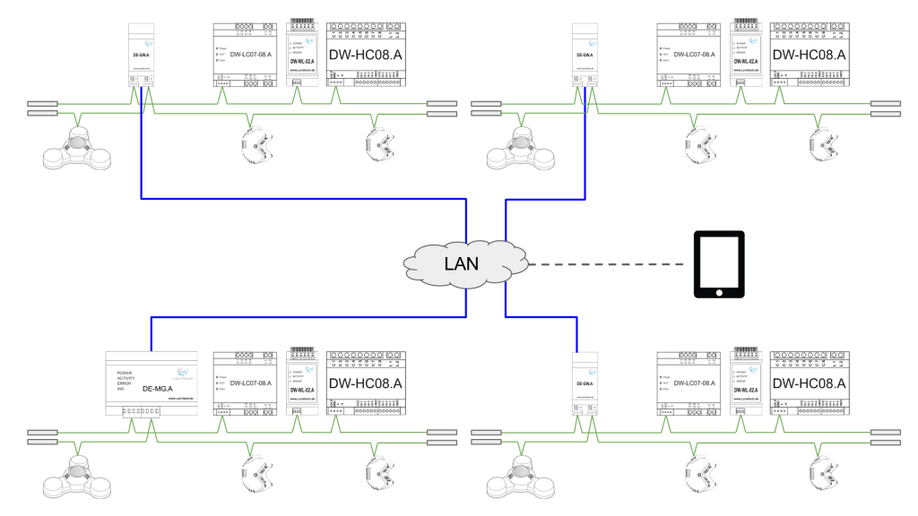
| If the building where the system is set up has several floors or 100 devices are not sufficient to perform all of your
tasks, additional extension modules are connected to the system. Each of them gives the user the ability to connect
100 more devices.
|
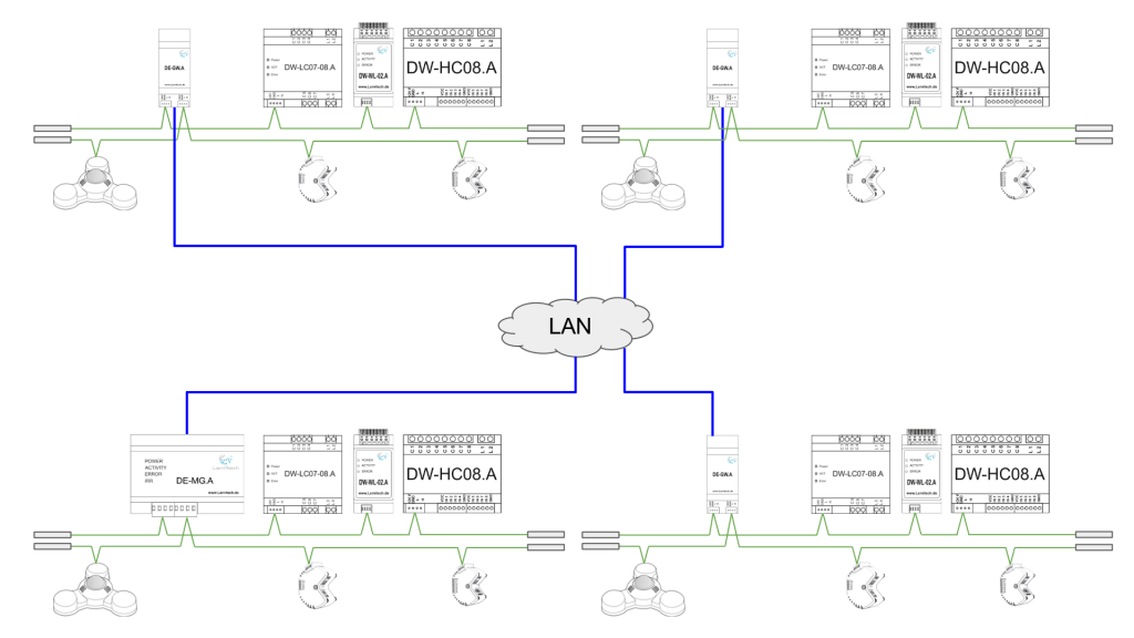
| As many extension modules as needed may be added, therefore the system can be expanded almost indefinitely. In
this way via the Local Area Network numerous CAN networks can be united into one network with a total number of
up to 1000 controlled modules.
|
| Tablets or smartphones get connected to the local area network via Wi-Fi. After installing the Larnitech application on
your tablet or phone, you can control the devices in the system.
|
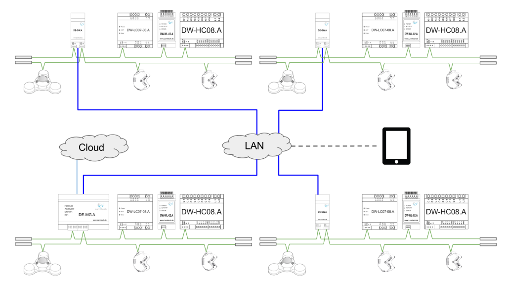
| The main gateway is connected to the cloud, which allows to get authorized remote access to the Smart Home.
|
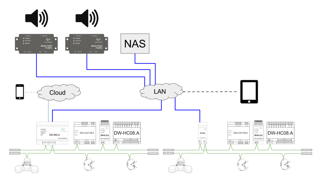
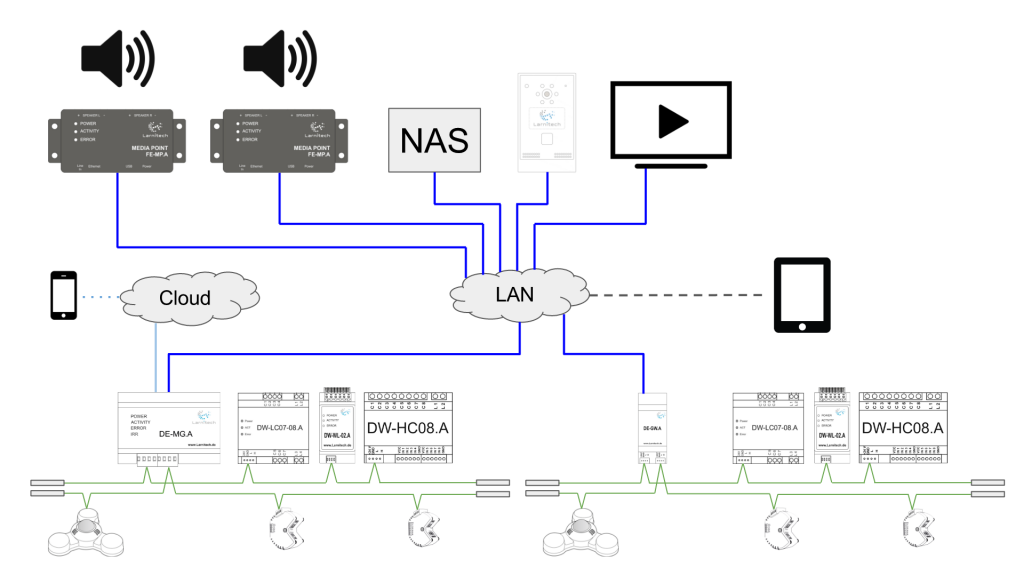
| The multiroom system is integrated via the local area network. The media points allow to playing music from your
home storage and Internet radio. The multiroom system is deeply integrated into the Smart Home system, which
allows using it in various scenarios. For example, when you leave home, the scenario ‘I’m gone’ can be activated. In
this scenario the system turns off the lighting, puts the climate control system in the energy saving mode and with the
help of the multiroom system can tell you about the unlocked back door or an open window.
Many media points can be connected to the system, which will allow listening to music in various areas. The music
may be taken from your network attached storage (NAS).
|
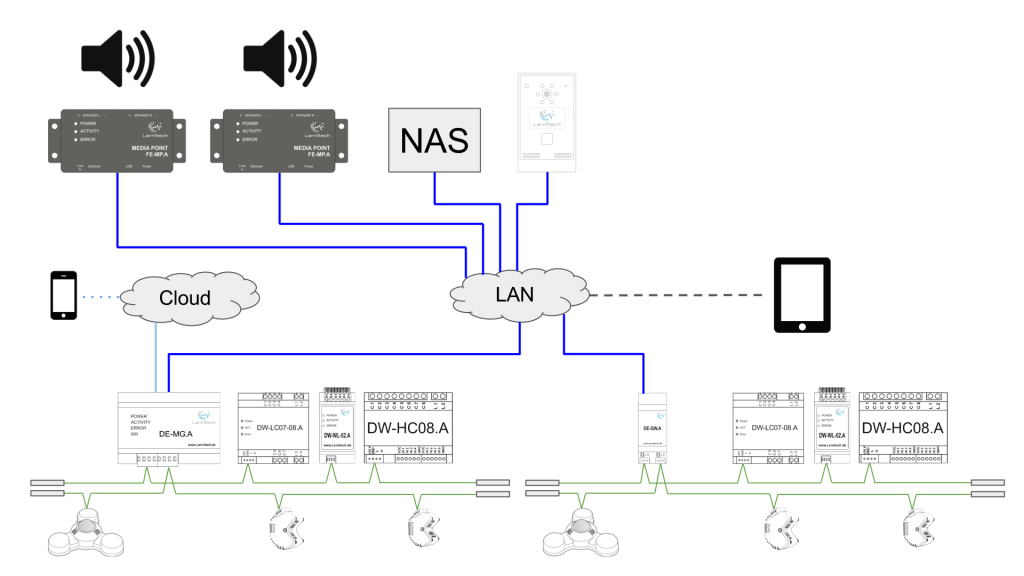
| The system allows the use of the intercom. When someone rings your doorbell, the multiroom system will play the
notification about it. Of course, it will only do that in the areas where you want the notification to be played. If the
property owner is not at home, the system will let them speak to the visitor via the application on their smartphone
or tablet.
|
| The multiroom system lets the user control smart TV and other devices which support the DLNA standard.
|
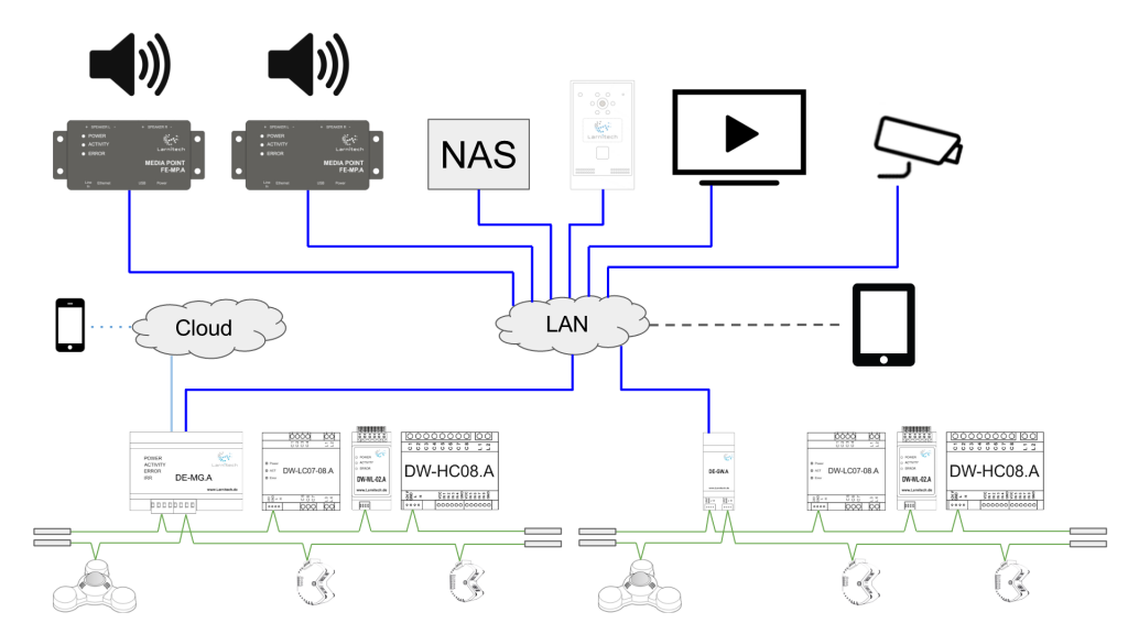
| If you connect the IP cameras to the system, you will be able to see the corresponding areas through our application.
|
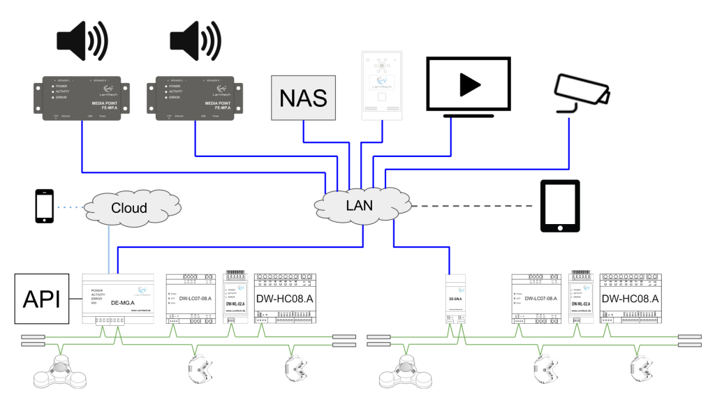
| The API can be provided by Larnitech, which lets the third-party applications, after they are authorized, get the
information from the Smart Home system and control its devices.
|
| Connecting an additional power supply to the CAN bus
|