Difference between revisions of "Metaforsa MF-10"
| Line 363: | Line 363: | ||
{{ConExC | {{ConExC | ||
|Caution: Before applying power to the module, you should properly configure access to the application. The contacts incorrectly configured can result in the module failure and/or failure of the equipment connected to it, and even a fire. | |Caution: Before applying power to the module, you should properly configure access to the application. The contacts incorrectly configured can result in the module failure and/or failure of the equipment connected to it, and even a fire. | ||
| − | |mf10exa8|Fig. 9|Any contact point (for example, 3) is used to connect the single-pole gate drive controllers. The example of connection is shown in '''Fig.9'''. | + | |mf10exa8|Fig. 9|Any contact point (for example, 3) is used to connect the single-pole gate drive controllers. The example of connection is shown in '''Fig.9'''.|.png|150}} |
| − | }} | ||
| − | |||
| − | |||
====Connection of double-pole gate actuator==== | ====Connection of double-pole gate actuator==== | ||
Revision as of 14:52, 21 July 2021
| MF-10 | |||||||
|---|---|---|---|---|---|---|---|
 | |||||||
| |||||||
| |||||||
Introduction
METAFORSA SMART HOUSE Installation Manual describes the procedure for its installation, assembly, operation and setting. While working with the system, you must strictly comply with all the requirements set out in this manual. Failure to comply may result in damage to the device, its failure, electric shock, fire and other fallout. The manufacturer reserves the right to make changes to this manual without prior notice. This manual is an integral part of the system and shall remain with the end-use customer.
Features
- 10 universal outputs support:
- Lights
- NC/NO heating valves
- Blinds
- 1 or 2-pole gates
- 1 or 2-pole valves
- NC/NO locks
- Fan coil units
- 16 Discreet inputs that support:
- Buttons
- Switches
- reed switches
- leak sensors
- motion detectors
- 4 digital inputs for up to 8 temperature sensors
- Extension port
- Relays with AgSnO2 contacts rated for 16A and 120A 20ms inrush current
- Cloud connection and control of all house systems
- Voice control (Siri, Alexa, Google Home)
- Plugins engine allows expanding the system possibilities (e.g. integrating with Satel, Philips Hue, IKEA lights)
- Safety against unauthorized intrusion ensured with RSA/AES256 encryption
- Push notifications from the system on your phone (also possible to receive through Telegram and Viber messengers)
- History (meter data for 1 year is stored)
- Plug and play (possibility for fast and user-friendly extension of the system)
- Regular system updates
- Large constantly updated database of scripts to meet all your needs
- Automatic daily backups via cloud with the possibility to restore the initial configuration
- Open API (which allows integrating Larnitech into other systems)
- Interactive and user-friendly LT SETUP Web interface available for advanced configuration
- Plug and play
- It is a completely ready-to-install Smart Home system kit
Safety requirements
To avoid the risk of fire, electric shock, damage to the system and / or personal injury, the system installation and assembly must be performed in accordance with the instructions listed below:
- all connection works must be carried out without power;
- use appropriate tools and personal protection against electric shock;
- do not use damaged cables, wires and connectors;
- avoid folding of cables and wires;
- do not pinch or kink the cables and wires by applying excessive force. Otherwise, inner conductors of the cable and wires may be stripped or broken;
- do not use the power socket with poor contacts to connect;
- do not exceed the load parameters limit specified in this manual;
- the supply conductors wire section is subject to the specifications for current density limit, insulation type and wire material. Light section can result in cable overheating and fire.
When working with the system after voltage supply NEVER:
- make connection/disconnection of connectors;
- open modules and sensors.
System configuration and purpose
Purpose of the system
METAFORSA SMART HOUSE is a ready-made solution for automation of residential and commercial premises, hotel complexes which includes the most highly desired features of Smart House.
The device has 10 control channels, 16 incoming sensor channels, and a digital sensors’ connection port.
| Universal outputs can be used to control: | Universal inputs allow you to connect: |
|---|---|
| Lighting | Buttons/switching units |
| Socket connectors | Magnetic reed switches |
| Underfloor heating | Magnetic reed switches |
| Curtain/gate actuators | Leakage sensors |
| Water supply/heating valves |
Digital sensors connection port
The digital sensors connection port allows you to connect a variety of digital sensors, such as temperature sensors, ambient light, humidity and other.
Expansion port
The expansion port allows you to upgrade the system by connecting auxiliary equipment, such as the control module for LED lighting, dimming, metering devices and other elements.
The package, which is completely ready-to-install, includes the basic hardware and software.
Package contents
The package comes standard with:
| Mainframe METAFORSA MF-10.А | 1 pc |
| Power supply unit MEANWELL DR-15-12 | 1 pc |
| Motion sensor Satel amber | 3 pcs |
| Leakage sensor FW-WL.A | 2 pcs |
| Temperature-sensitive element FW-TS.A | 4 pcs |
| Magnetic reed switch (window/door position sensor) | 4 pcs |
| Ethernet-cable noise filter | 1 pc |
| Power supply cord | 1 pc |
| Manual | 1 pc |
Basic technical specifications of the System
The basic specifications and characteristics of the module METAFORSA MF-14.A are shown in table 1
| Specification | Meaning |
|---|---|
| Output ports | |
| Number of switched channels | 10 |
| Number of switched groups | 3 |
| Commutation voltage | 0-250 V AC/DC |
| Peak load (one channel) | 8A |
| Peak load (one group) | 20A |
| Peak load (device) | 45A |
| Power supply cable connection type | connector |
| Permissible section of power supply cable to connect in socket: single-conductor cable multiple-conductor cable tipped multiple-conductor cable |
0.5 … 4mm2 0.5 … 4mm2 0.5 … 2.5mm2 |
| Input ports | |
| Number of discrete inputs | 16 |
| Number of digital inputs | 4 |
| Current maximum rating on the direct-current voltage connectors | 50mA |
| Other | |
| Operating ambient temperature | 0 … +45°С |
| Storage/transportation temperature | -20 … +60°С |
| Permissible humidity | 0 … 95% (non-condensing) |
| Supply voltage | 11.5 … 15.5 V DC |
| Maximum demand | 1А |
| Available interfaces | Ethernet, CAN, OneWire |
| Bus type | CAN (4-wire) |
| CAN (4-wire) | 800 m* (twisted pair 5 cat) |
| CAN wire type | FTP Cat 5E |
| CAN connection type | connector |
| Digital line maximum length | 30 m |
| Digital line wirde type | UTP/FTP Cat 5E |
| Digital line connection type | Connector RJ-12 |
| LAN maximum length | 100 m |
| LAN wire type | UTP/FTP Cat 5E |
| LAN connection type | Connector RJ-45 |
| Dimensional specifications | 9U, 156x110x58 mm |
| Shell material | ABS plastic |
| Casing | IP40 |
| Equipment installation type | DIN-rail (EN 60715) |
| Weight | 400 g |
* – installing additional power supply units is required for long lines; the maximum length of the line may be reduced by various interference factors
General structure of the System
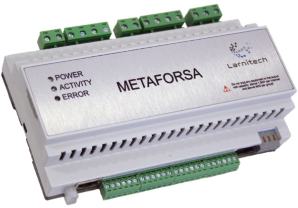
Module general view is shown in fig. 1

| 1-5 | — connectors for load application and power supply |
| 6 | — device status indication |
| 7 | — power connector |
| 8 | — Ethernet network connector |
| 9-12 | — connectors for digital sensors and buttons/switching units |
| 13 | — OneWire interface connector (for digital sensors) |
| 14 | — connector for expansion module. |
Overview of the METAFORSA device external connectors: In the upper part of the casing (fig. 1) there are 5 connectors with screw clamps. Connectors: (1) – contact points (L1, L2), (3) – contact points (L3, L4) and (5) – contact point (L5) – phase conductor connection for load switching of the channels C1-C4, C5-C8, and C9-C10 respectively. The parallel connection of two contact points is used in connectors (1) and (3) in order to increase the capacity. Connectors: (2) – C1-C4 contact points, (4) – contact points C5-C8 and (5) – C9-C10 – are used for load connection (of actuators – lights, valves, curtain drives, etc.). Internal circuit for output switching is shown in fig. 2.

- connector (7) — module power supply connection;
- connector (8) — Ethernet network connection;
- connectors (9-12) — four six-point connectors for digital sensors connection – motion, leakage, reed switch sensors, and button/switching unit sensors;
- connector (13) — OneWire digital sensors bus connection;
- connector (14) — expansion module connection.
The physical configuration and contact point assignment of each connector are shown in table 2.
| Connector | Contact | Assignment |
|---|---|---|
1, 3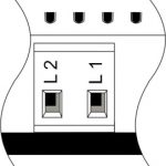 |
L1-2 L3-4 | Phase conductor connection for C1-C8 channels load switching |
2, 4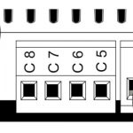 |
C1-4 C5-8 | Load application (light lamps, thermal actuators, etc.) |
5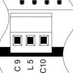 |
С9 L5 С10 | Connection of curtain/jalousie/shutter actuators, valve, lamps, gate controllers, etc.: С9, С10 — outputs for load application L5 — connection of group phase supply wire |
| 6 Device status indicators |
The module status indicators are described in table 3 | |
7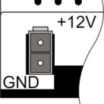 |
+12V GND | +12V — module power supply by an external 12 V power supply GND — common |
8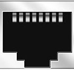 |
RJ45 | Connector for LAN connectivity |
9-12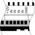 |
+12V In1 … In16 GND | Controlling devices connection (buttons, magnetic reed switches, motion or leakage sensors): +12V — sensor power output +12 V In1 … In16 — logic inputs (0-12 V) GND — common |
13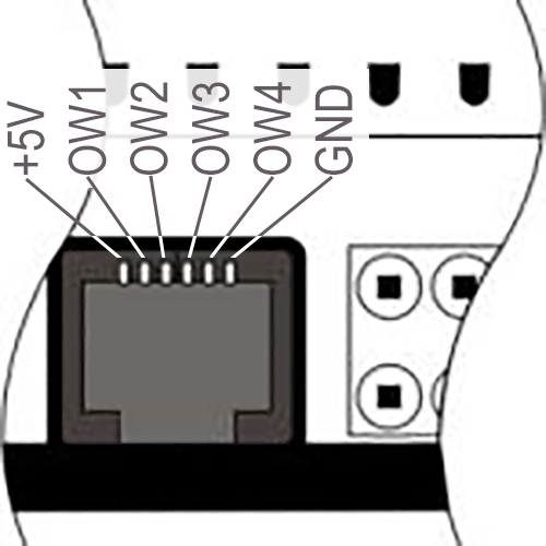 |
OneWire | Digital sensors connection (temperature) VCC — sensors power supply output +5V OW1-OW4 — OneWire data buses GND — common |
14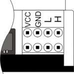 |
VCC GND L H |
External modules connection for CAN-bus VСС — 12V output for external devices power supply GND — common L — CAN-L data bus H — CAN-H data bus |
| Indicator | Status | Description |
|---|---|---|
| Power | Power | |
| Power not available | ||
| Activity | Data communication | |
| Data communication not available | ||
| Error | No errors | |
| Communication error | ||
| Software update |
System installation and assembly
Before connecting the system, you must:
- site the sensor and actuators (if not pre-installed), set the sensors and actuators;
- site the module and power supply.
Note: The module must be installed near the power supply voltage source.
- AC power voltage must be provided to the system input through the circuit breaker assembly. It should be installed close to the power supply.
- The load is applied through the circuit breaker assembly. It can be both common – for all groups, and individual – for each group (fig. 3,4).

Fig 3.

Fig 4.
Notes:
- The power of circuit breaker assembly must comply with the load capacity;
- Nothing else than the phase conductors can be connected to the module, the neutral wire is connected separately.
Typical diagram of METAFORSA MF-10.A module connection is shown in fig. 5.

Fig. 5 Typical connection diagram
Connection of the actuators
Connection of the lights/electric contactor/heating thermal actuator
 Fig. 6 |
Such actuators as light, electric contactor, heating thermal actuator should be switched on any of the outputs 1 – 10, the neutral wire and the ground wire should be connected directly to the switchboard. The example of connection is shown in Fig.6. |
Connection of high load device
 |
Recomended contactors:
|
Connection of single-pole water/gas supply valve
| Caution: Before applying power to the load, make sure that the output configuration of METAFORSA module is correct. The incorrect configuration or incorrect connection can cause the module failure and/or failure of the equipment connected to it, and even a fire. | |
 Fig. 7 |
The single pole water/gas supply valve is connected to any of the outputs of 1 – 10, the (neutral wire and the ground wire are connected directly to the switchboard. The example of connection is shown in Fig.7. |
Connection of double-pole water/gas supply valve
| Caution: Before applying power to the valve, it is necessary to ensure the output configuration of METAFORSA module is correct. The incorrect configuration can cause the voltage application simultaneously to both channels of the valve, which may result in the module failure and/or failure of the equipment connected to it, and even a fire. | |
 Fig. 8 |
Two adjacent contact points (for example, 3, 4) are used to connect the double-pole water/gas supply valve; in these conditions the neutral wire and the ground wire are connected directly to the switchboard. The example of connection is shown in Fig.8. |
Connection of single-pole gate actuator
| Caution: Before applying power to the module, you should properly configure access to the application. The contacts incorrectly configured can result in the module failure and/or failure of the equipment connected to it, and even a fire.
| |
 Fig. 9 |
Any contact point (for example, 3) is used to connect the single-pole gate drive controllers. The example of connection is shown in Fig.9. |
Connection of double-pole gate actuator
| Caution: Before applying power to the module, you must properly configure the outputs in the application. The contacts configured incorrectly can lead to simultaneous power supply to both channels, resulting in the module failure and/or failure of the equipment connected to it, and even a fire.
| |
 Fig. 10 |
Two adjacent contact points (for example, 3, 4) should be used to connect the double-pole gate drive controller. The example of connection is shown in Fig.10. |
Connection of curtain/jalousie/shutter actuator with 220V force control
| Caution: Before applying power to the module, you must properly configure the outputs in the application. The contacts configured incorrectly can lead to simultaneous power supply to both channels, resulting in the module failure and/or failure of the equipment connected to it, and even a fire.
| ||
| [[File:mf10exa10.jpg | mf10exa10]] Fig. 11 |
Two adjacent contact points (for example, 3, 4) should be used to connect the curtain/jalousie/rolladens actuator, in these conditions the neutral wire and the ground wire are connected directly to the switchboard. The example of connection is shown in Fig.11. |
Connection of curtain/jalousie/shutter actuator with low-voltage control
| Caution: Before applying power to the module, you must properly configure the outputs in the application. The contacts configured incorrectly can lead to simultaneous power supply to both channels, resulting in the module failure and/or failure of the equipment connected to it, and even a fire.
| ||
| [[File:mf10exa11.jpg | mf10exa11]] Fig. 12 |
Two adjacent contact points (for example, 3, 4) should be used to connect the curtain/jalousie/rolladens actuator with low-voltage control. The example of connection is shown in Fig.12. |