Difference between revisions of "Translations:Metaforsa2 MF-14/29/en"
Jump to navigation
Jump to search
(Importing a new version from external source) |
(Importing a new version from external source) |
||
| Line 18: | Line 18: | ||
|[[File:OW.png|80px|frameless]] ||OneWire|| Digital sensors connection (temperature)<br>VCC — sensors power supply output +5V<br>OW1-OW4 — OneWire data buses<br>GND — common | |[[File:OW.png|80px|frameless]] ||OneWire|| Digital sensors connection (temperature)<br>VCC — sensors power supply output +5V<br>OW1-OW4 — OneWire data buses<br>GND — common | ||
|- | |- | ||
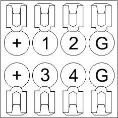
| − | |[[File:Can.jpg|80px|frameless]] ||VCC<br>GND<br>L<br>H|| External modules connection for CAN-bus<br>VСС — | + | |[[File:Can.jpg|80px|frameless]] ||VCC<br>GND<br>L<br>H|| External modules connection for CAN-bus<br>VСС — 24V output for external devices power supply<br>GND — common<br>L — CAN-L data bus<br>H — CAN-H data bus |
|} | |} | ||
Latest revision as of 14:50, 8 February 2024
| Connector | Contact | Assignment |
|---|---|---|
 |
1-10 | Load application (light lamps, thermal actuators, etc.) |
| D1-4, L, N | Load application (dimming lamps) | |
| Device status indicators | The module status indicators are described in table 3 | |
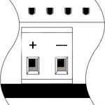 |
+24V GND |
+24V — module power supply by an external 24 V power supply GND — common |
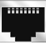 |
RJ45 | Connector for LAN connectivity |
| In1-12, In13-24 GND | Controlling devices connection (buttons, magnetic reed switches, motion or leakage sensors): +12V — sensor power output +12 V In1 … In24 — logic inputs (0-12 V) GND — common | |
 |
OneWire | Digital sensors connection (temperature) VCC — sensors power supply output +5V OW1-OW4 — OneWire data buses GND — common |
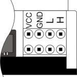 |
VCC GND L H |
External modules connection for CAN-bus VСС — 24V output for external devices power supply GND — common L — CAN-L data bus H — CAN-H data bus |