LED-DRV
Jump to navigation
Jump to search
| LED-DRV | |||||||
|---|---|---|---|---|---|---|---|
 | |||||||
| |||||||
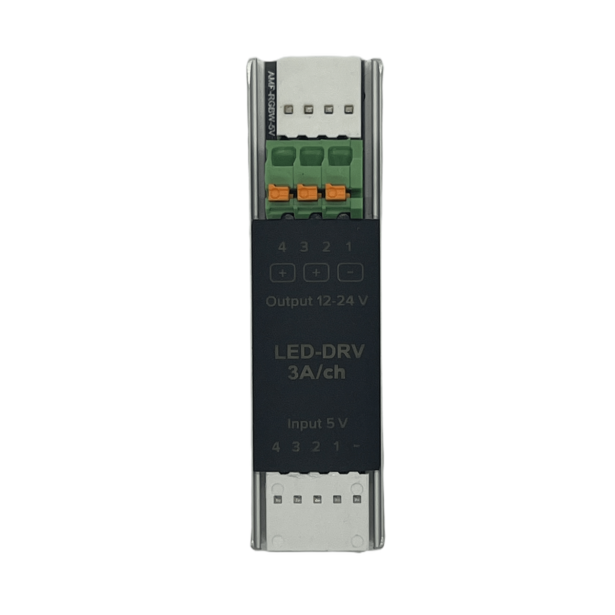
4-CHANNEL LED Driver
This module allows interpretation of controlling signals from IO connections for 12/24V LED/RGB strips.
CAUTION! All work related to the installation, connection, setting up, service and support must be carried out by qualified personnel with sufficient skills and experience in working with electrical equipment. To avoid the risk of fire, electric shock, damage to the system and/or personal injury, the system installation and assembly must be performed in accordance with the instructions listed below:
- all connectivity work must be carried out with the power turned OFF;
- use appropriate tools and personal protection against electric shock;
- do not use damaged cables, wires and connectors;
- avoid folding the cables and wires;
- do not apply excessive force to the wires by kinking or pressing them too hard: the inner conductors of the cables and wires may get stripped or damaged;
- do not use the power socket with poor contacts to connect;
- do not exceed the load limit parameters specified in the manual;
- the supply conductors wire section is subject to the specifications for current density limit, insulation type and wire material. Light section can result in cable overheating and fire.
When the power is on, NEVER:
- connect/disconnect the connectors;
- open modules and sensors.
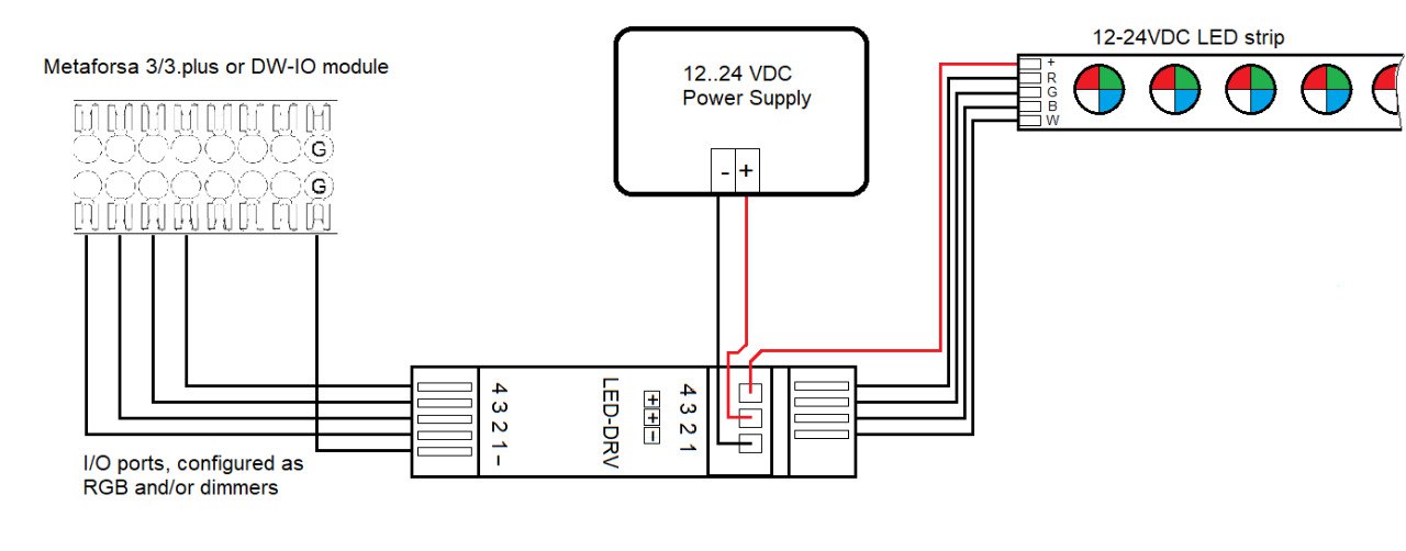
Example of connection
Module parameters
| Parameter name | Value |
|---|---|
| Output channels qty | 4 |
| Input voltage | 5V |
| Current type | DC |
| Adjustment type | PWM |
| Max load per channel | 3A |
| Power supply | 11.5 … 27.5 V DC |
| Equipment installation type | Free |
| Case material | ABS |
| Protection | IP40 |
| Temperature range | -10 … +50 °C |
| Size | 65x18x15 mm |
| Weight | 25 g |
Module installation and connection procedure
- Connect the outputs.
- Configure the module using LT Setup.
- Apply power to the load.
- Check all equipment for proper operation.
Module shut-off and deinstallation procedure
- Disconnect the power from the load.
- Disconnect the outputs.