Translations:Larnitech Smart Home System Architecture/1/en
Jump to navigation
Jump to search
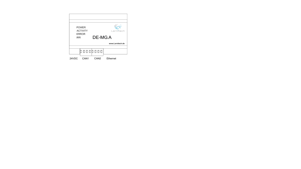
| The Main Gateway is the core device of the system. Its main task is to configure the system, and provide the logic for
its operation. It also keeps track of the sensors data and provides authorized access to the system. The Main Gateway is connected to the local network. It has 2 CAN bus ports.
|
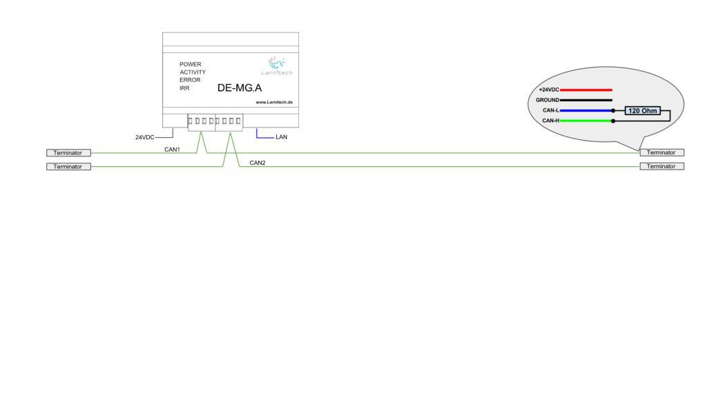
| The CAN bus is used to connect the sensors and actuators to the system. Terminators, 120 Ohm resistors, need to be
installed at the end of the CAN bus.
|
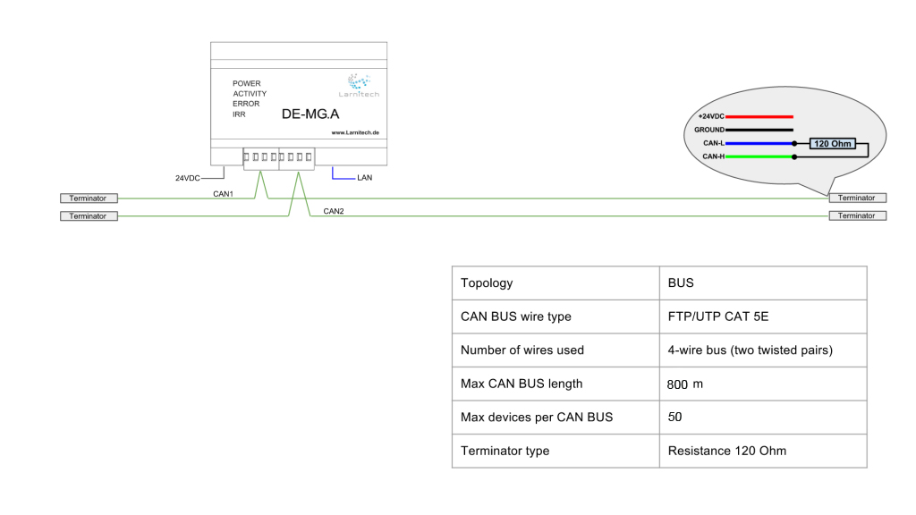
| As can be seen from the table below, a Four-wire bus is used (two twisted pairs) with a maximum length of a eight hundred
metres. A maximum of 50 devices can be connected to each CAN bus.
|
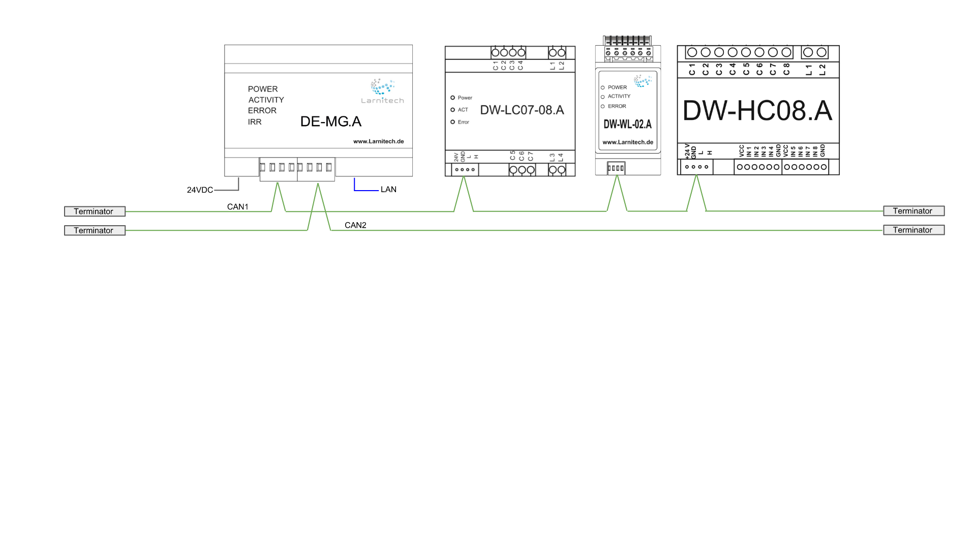
| The following diagram shows how modules can be connected to the system. In the drawing below a 7-channel
actuator, a leak control module and a heating control module have been connected to the first CAN bus.
|
| The second CAN bus has a four-in-one multi-sensor, a dimmer and a two-channel pattress box space actuator. In such |