Difference between revisions of "Translations:Metaforsa MF-10/32/en"
From Larnitech wiki page
Jump to navigation
Jump to search
Tags: Mobile web edit Mobile edit |
(No difference)
|
Latest revision as of 14:57, 2 January 2022
Table2
| Connector |
Contact |
Assignment
|
1, 3
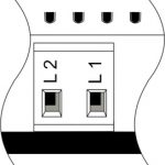 |
L1-2 L3-4 |
Phase conductor connection for C1-C8 channels load switching
|
2, 4
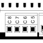 |
C1-4 C5-8 |
Load application (light lamps, thermal actuators, etc.)
|
5
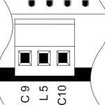 |
С9 L5 С10 |
Connection of curtain/jalousie/shutter actuators, valve, lamps, gate controllers, etc.: С9, С10 — outputs for load application L5 — connection of group phase supply wire
|
6
Device status indicators |
The module status indicators are described in table 3
|
7
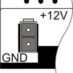 |
+12V GND |
+12V — module power supply by an external 12 V power supply GND — common
|
8
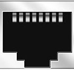 |
RJ45 |
Connector for LAN connectivity
|
9-12
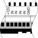 |
+12V In1 … In16 GND |
Controlling devices connection (buttons, magnetic reed switches, motion or leakage sensors): +12V — sensor power output +12 V In1 … In16 — logic inputs (0-12 V) GND — common
|
13
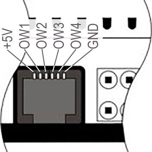 |
OneWire |
Digital sensors connection (temperature) VCC — sensors power supply output +5V OW1-OW4 — OneWire data buses GND — common
|
14
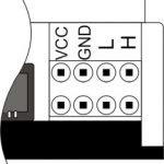 |
VCC
GND
L
H |
External modules connection for CAN-bus VСС — 12V output for external devices power supply GND — common L — CAN-L data bus H — CAN-H data bus
|