Difference between revisions of "DE-MG"
m |
|||
| (11 intermediate revisions by one other user not shown) | |||
| Line 1: | Line 1: | ||
| + | <languages/> | ||
| + | <translate> | ||
{{revisionChanger |hasB=1 |hasC=1}} | {{revisionChanger |hasB=1 |hasC=1}} | ||
{{Infobox module | {{Infobox module | ||
| Line 8: | Line 10: | ||
| canportqty = 2 | | canportqty = 2 | ||
| canbuslength = 800 m (twisted pair 5 cat) | | canbuslength = 800 m (twisted pair 5 cat) | ||
| − | | maxcancurrent = | + | | maxcancurrent = 700 mA |
| voltage = 11.5...27.5 V DC<br>24V, 2.5A Recommended | | voltage = 11.5...27.5 V DC<br>24V, 2.5A Recommended | ||
| dim = 2U, 36x102x58 mm | | dim = 2U, 36x102x58 mm | ||
}} | }} | ||
| − | ==MAIN GATEWAY== | + | ==MAIN GATEWAY== <!--T:1--> |
| + | <!--T:2--> | ||
It is used for accumulation and storage of system data. The device determines the logical scheme of the system and allows authorized access to the system via the Internet. It also converts Ethernet into CAN bus and vice versa. DE-MG has a built-in IR receiver.The DE-MG can be controlled via cloud with a securely encrypted signal. The system history from all other devices and sensors is stored on the DE-MG for one year. Its plug and play feature means that it automatically detects and configures new Larnitech devices that are added to the system. A large and constantly updated database of ready-made scripts ensures that your home does everything your heart may desire. Get things going by telling your home what to do with the help of Siri, Alexa or Google Home. Get push notifications on your phone whenever the system has things to tell you and enjoy the ultimate control at your fingertips | It is used for accumulation and storage of system data. The device determines the logical scheme of the system and allows authorized access to the system via the Internet. It also converts Ethernet into CAN bus and vice versa. DE-MG has a built-in IR receiver.The DE-MG can be controlled via cloud with a securely encrypted signal. The system history from all other devices and sensors is stored on the DE-MG for one year. Its plug and play feature means that it automatically detects and configures new Larnitech devices that are added to the system. A large and constantly updated database of ready-made scripts ensures that your home does everything your heart may desire. Get things going by telling your home what to do with the help of Siri, Alexa or Google Home. Get push notifications on your phone whenever the system has things to tell you and enjoy the ultimate control at your fingertips | ||
| − | ==Features== | + | ==Features== <!--T:3--> |
*One DE-MG can manage up to 1000 devices | *One DE-MG can manage up to 1000 devices | ||
*Cloud connection and control of all house systems | *Cloud connection and control of all house systems | ||
| Line 33: | Line 36: | ||
*The module supplies power to CAN bus, ensuring system reliability and stable operation | *The module supplies power to CAN bus, ensuring system reliability and stable operation | ||
| + | <!--T:4--> | ||
<div class="caution"> | <div class="caution"> | ||
CAUTION! All work related to the installation, connection, setting up, service and support must be carried out by qualified personnel with sufficient skills and experience in working with electrical equipment.To avoid the risk of fire, electric shock, damage to the system and/or personal injury, the system installation and assembly must be performed in accordance with the instructions listed below: | CAUTION! All work related to the installation, connection, setting up, service and support must be carried out by qualified personnel with sufficient skills and experience in working with electrical equipment.To avoid the risk of fire, electric shock, damage to the system and/or personal injury, the system installation and assembly must be performed in accordance with the instructions listed below: | ||
| Line 48: | Line 52: | ||
</div> | </div> | ||
| − | ==Module view== | + | ==Module view== <!--T:5--> |
| − | [[File:DE- | + | [[File:DE-MGC VIEW.png|300px]] |
#Indicators | #Indicators | ||
#IR Reсiever | #IR Reсiever | ||
#Recovery button | #Recovery button | ||
| − | |||
#Power supply | #Power supply | ||
#CAN1 | #CAN1 | ||
| Line 59: | Line 62: | ||
#Ethernet | #Ethernet | ||
| − | ==Сonnection example== | + | ==Сonnection example== <!--T:6--> |
| − | [[File:DE- | + | [[File:DE-MGC EXA.png|800px]] |
| − | ==Module dimensions== | + | ==Module dimensions== <!--T:7--> |
| − | [[File:DE- | + | <!--T:8--> |
| + | [[File:DE-MGC DIM.png|400px]] | ||
| − | ==Connectorss== | + | <!--T:9--> |
| + | <!--==Connectorss== | ||
| + | <!--T:10--> | ||
[[File:DE-MG CONN.jpg|400px]] | [[File:DE-MG CONN.jpg|400px]] | ||
| + | --> | ||
| − | ==Module parameters== | + | ==Module parameters== <!--T:11--> |
| + | <!--T:12--> | ||
{|class="wikitable" | {|class="wikitable" | ||
|- | |- | ||
| Line 106: | Line 114: | ||
|Temperature range||-10 … +50°C | |Temperature range||-10 … +50°C | ||
|- | |- | ||
| − | |Size|| | + | |Size||2U, 36x102x58 mm |
|- | |- | ||
|Weight||145 g | |Weight||145 g | ||
| Line 112: | Line 120: | ||
<nowiki>*</nowiki> – installing additional power supply units is required for long lines; the maximum length of the line may be reduced by various interference factors | <nowiki>*</nowiki> – installing additional power supply units is required for long lines; the maximum length of the line may be reduced by various interference factors | ||
| − | ==Powering the bus with an external power supply== | + | ==Powering the bus with an external power supply== <!--T:13--> |
| + | <!--T:14--> | ||
[[File:CAN-POWERING.png|400px]] | [[File:CAN-POWERING.png|400px]] | ||
| − | ==Indication of module operation== | + | ==Indication of module operation== <!--T:15--> |
| − | {{ | + | <!--T:16--> |
| + | {{indication|hideLast= 1}} | ||
| + | </translate> | ||
Latest revision as of 09:28, 10 December 2021
| DE-MG | |||||||||||||||
|---|---|---|---|---|---|---|---|---|---|---|---|---|---|---|---|
 | |||||||||||||||
| |||||||||||||||
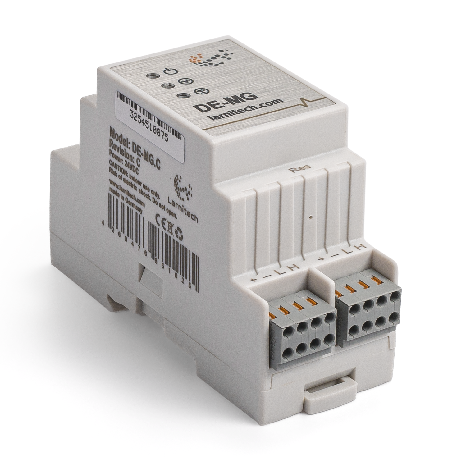
MAIN GATEWAY
It is used for accumulation and storage of system data. The device determines the logical scheme of the system and allows authorized access to the system via the Internet. It also converts Ethernet into CAN bus and vice versa. DE-MG has a built-in IR receiver.The DE-MG can be controlled via cloud with a securely encrypted signal. The system history from all other devices and sensors is stored on the DE-MG for one year. Its plug and play feature means that it automatically detects and configures new Larnitech devices that are added to the system. A large and constantly updated database of ready-made scripts ensures that your home does everything your heart may desire. Get things going by telling your home what to do with the help of Siri, Alexa or Google Home. Get push notifications on your phone whenever the system has things to tell you and enjoy the ultimate control at your fingertips
Features
- One DE-MG can manage up to 1000 devices
- Cloud connection and control of all house systems
- Viewing security cameras via cloud (for authorized users)
- Voice control (Siri, Alexa, Google Home)
- Plugins engine allows expanding the system possibilities (e.g. integrating with Satel, Philips Hue, IKEA lights)
- Safety against unauthorized intrusion ensured with RSA/AES256 encryption
- Push notifications from the system on your phone (also possible to receive through Telegram and Viber messengers)
- History (meter data for 1 year is stored)
- Plug and play (possibility for fast and user-friendly extension of the system)
- Regular system updates
- Large constantly updated database of scripts to meet all your needs
- Automatic daily backups via cloud with the possibility to restore the initial configuration
- Open API (which allows integrating Larnitech into other systems)
- Interactive and user-friendly LT SETUP Web interface available for advanced configuration
- The module supplies power to CAN bus, ensuring system reliability and stable operation
CAUTION! All work related to the installation, connection, setting up, service and support must be carried out by qualified personnel with sufficient skills and experience in working with electrical equipment.To avoid the risk of fire, electric shock, damage to the system and/or personal injury, the system installation and assembly must be performed in accordance with the instructions listed below:
- all connectivity work must be carried out with the power turned OFF;
- use appropriate tools and personal protection against electric shock;
- do not use damaged cables, wires and connectors;
- avoid folding the cables and wires;
- do not apply excessive force to the wires by kinking or pressing them too hard: the inner conductors of the cables and wires may get stripped or damaged;
- do not use the power socket with poor contacts to connect;
- do not exceed the load limit parameters specified in the manual;
- the supply conductors wire section is subject to the specifications for current density limit, insulation type and wire material. Light section can result in cable overheating and fire.
When the power is on, NEVER:
- connect/disconnect the connectors;
- open modules and sensors.
Module view
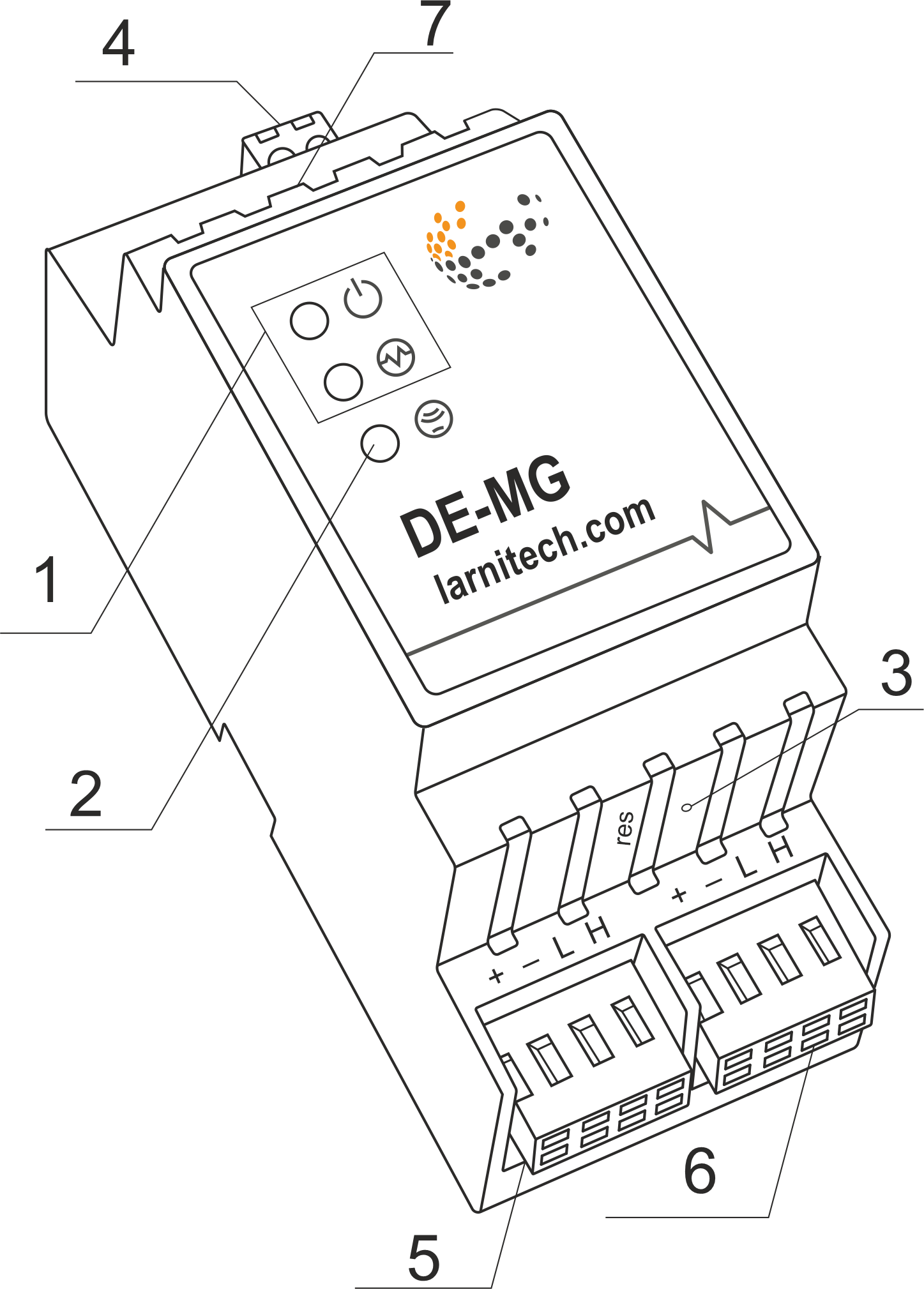
- Indicators
- IR Reсiever
- Recovery button
- Power supply
- CAN1
- CAN2
- Ethernet
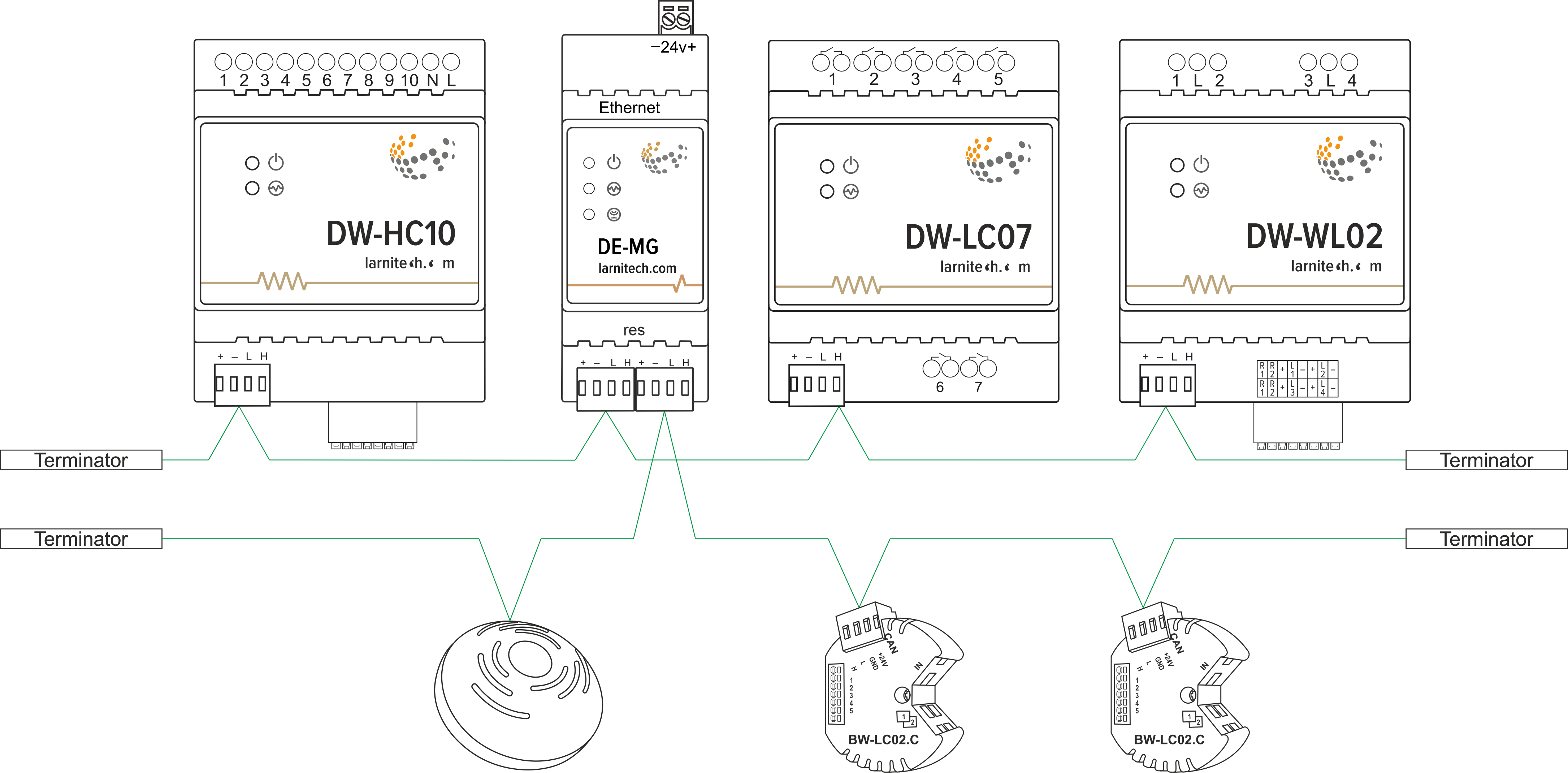
Сonnection example
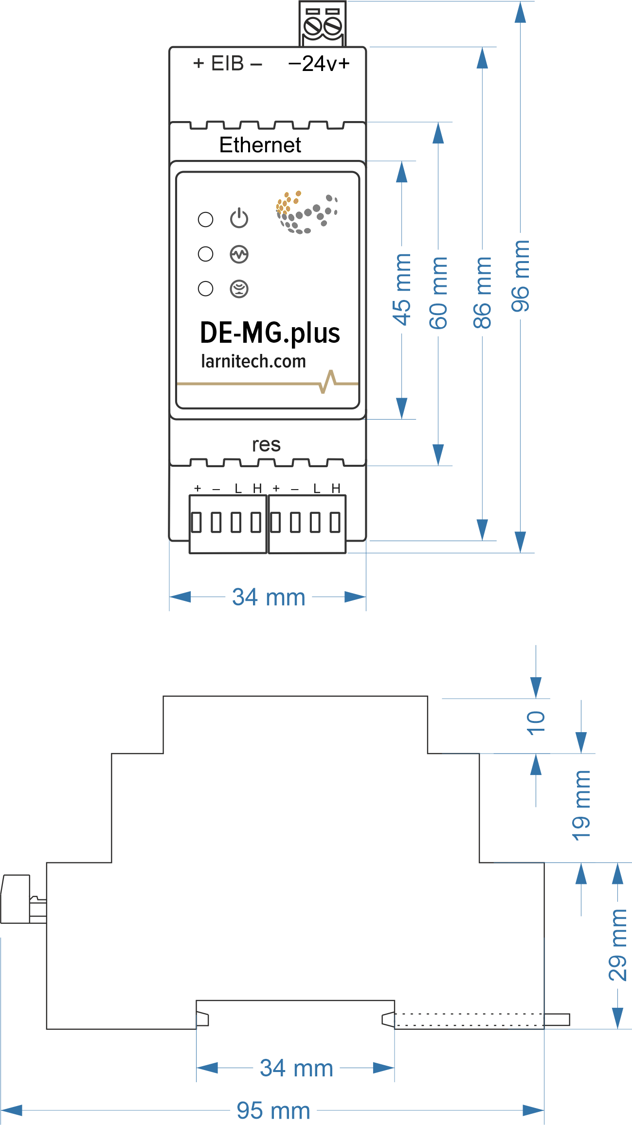
Module dimensions
Module parameters
| Parameter name | Value |
|---|---|
| Type of connection | CAN, Ethernet |
| Input/output interfaces | Ethernet, 2xCAN |
| Data speed | 10/100Mb/s |
| Max CAN deviсes | 100(50 per CAN) |
| CAN bus topology | BUS |
| Number of CAN ports | 2 |
| Power supply | 11.5 … 27.5 V DC 24V, 2.5A Recommended |
| Max own current (24V) | 140mA |
| Max CAN bus length | 800 m* (twisted pair 5 cat) |
| Max current per CAN bus | 700mA |
| IR Receiver angle | 30° |
| Case material | ABS |
| Protection | IP40 |
| Equipment installation type | DIN-rail (EN 60715) |
| Temperature range | -10 … +50°C |
| Size | 2U, 36x102x58 mm |
| Weight | 145 g |
* – installing additional power supply units is required for long lines; the maximum length of the line may be reduced by various interference factors
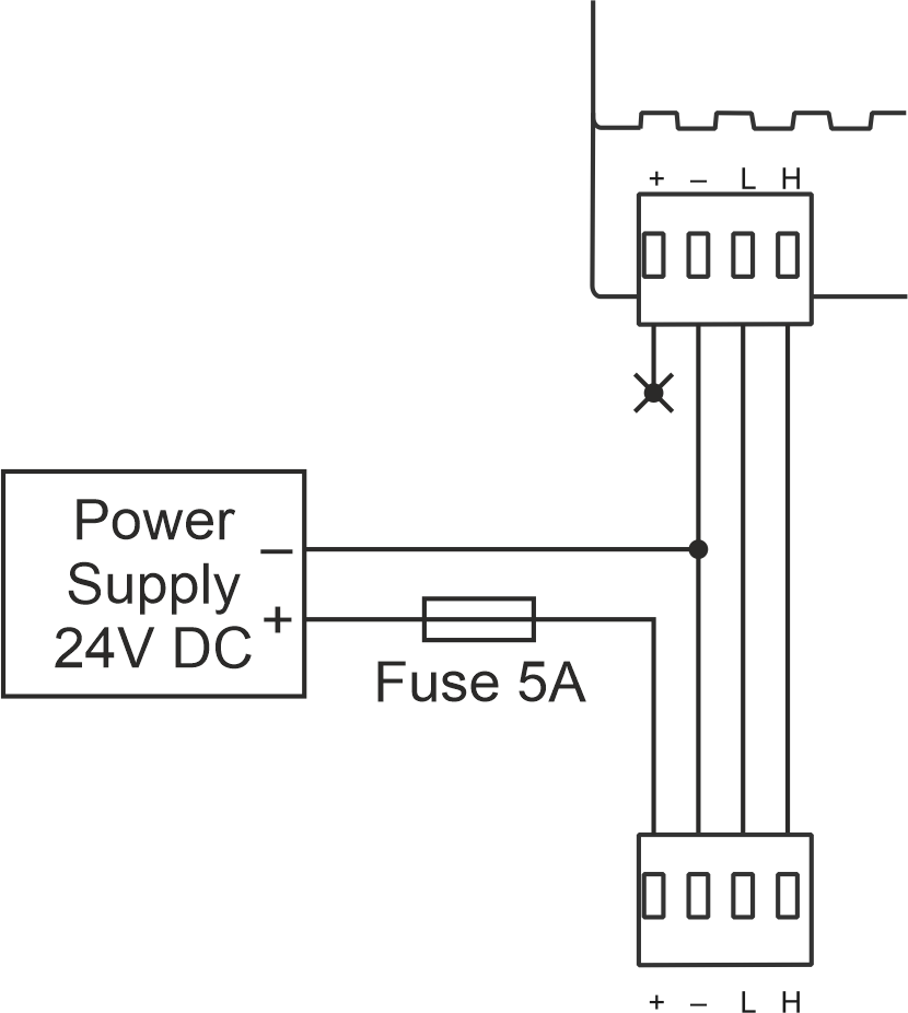
Powering the bus with an external power supply
Indication of module operation
| Indicator | Status | Description |
|---|---|---|
| Device in bootloader | ||
| Downloading firmware | ||
| Flashing firmware |