Difference between revisions of "Quick Start Guide/cs"
(Created page with "Pokud po instalaci a spuštění aplikace nedojde k automatickému navázání připojení, je třeba se připojit k síti Wi-Fi "Larnitech_case_5G" pomocí Vašeho mobilního...") |
(Created page with "Hlavní obrazovka aplikace obsahuje několik klíčových prvků. V levém horním rohu se nachází nabídka "výběr oblasti" <span style="font-size: 30px; vertical-align: m...") |
||
| Line 74: | Line 74: | ||
<hr> | <hr> | ||
| − | + | Hlavní obrazovka aplikace obsahuje několik klíčových prvků. V levém horním rohu se nachází nabídka "výběr oblasti" <span style="font-size: 30px; vertical-align: middle;">①</span>. | |
| − | + | Chcete-li spravovat jednu z dostupných oblastí, stačí na ni kliknout <span style="font-size: 30px; vertical-align: middle;">②</span>. | |
| − | + | Dále jsou zde ikony, které umožňují vybrat spouštěče, senzory, klimatizaci, multimédia, dálkové ovládání a kamery <span style="font-size: 30px; vertical-align: middle;">③</span>. V pravém rohu se nachází ikona pro další nabídku <span style="font-size: 30px; vertical-align: middle;">④</span>. Uvnitř ikony můžete také vidět stav aktuálního připojení. | |
[[File:DemoCase7.png|1000x800px]] | [[File:DemoCase7.png|1000x800px]] | ||
<hr> | <hr> | ||
Revision as of 13:18, 3 November 2023
Rychlé spuštění/vybalení.
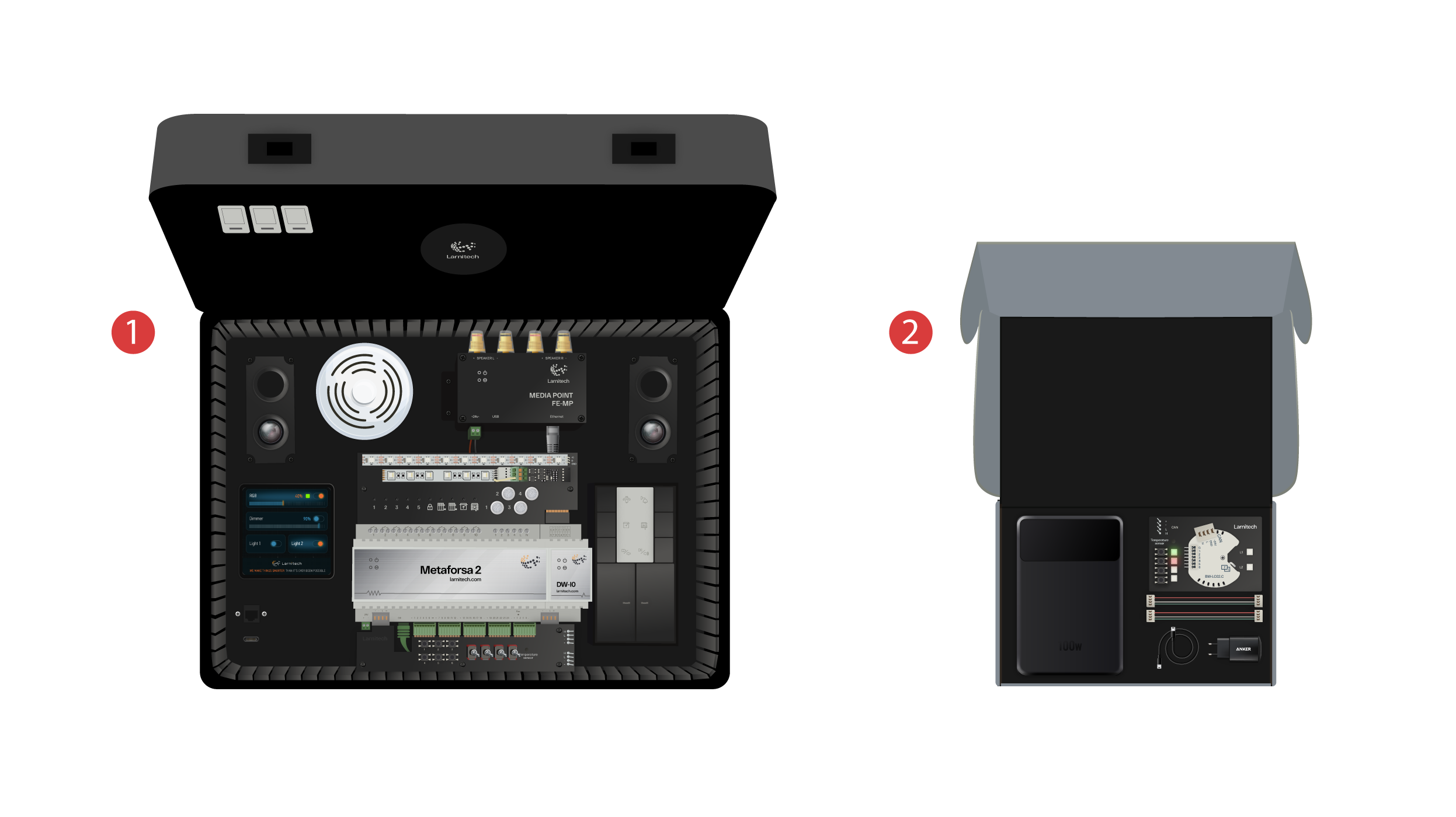
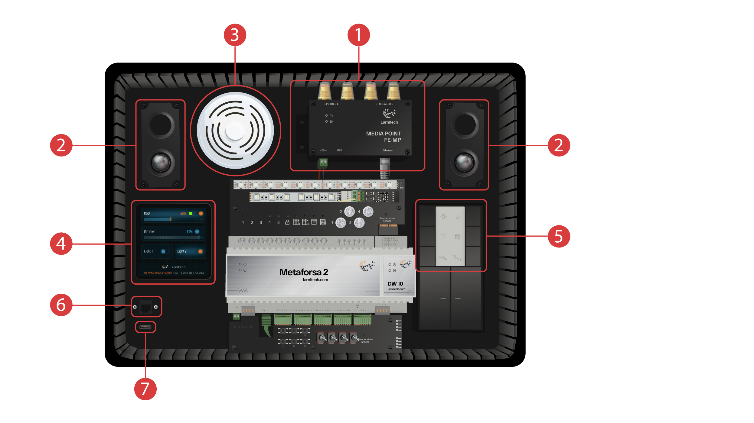
Na našem kanálu vítáme každého! Toto video je návodem, jak rychle a bez námahy nastavit systém Larnitech. Nastavení bude provedeno pomocí ukázkového kufříku. Výuková sada obsahuje demonstrační kufřík ① a krabici s několika dalšími položkami ②.
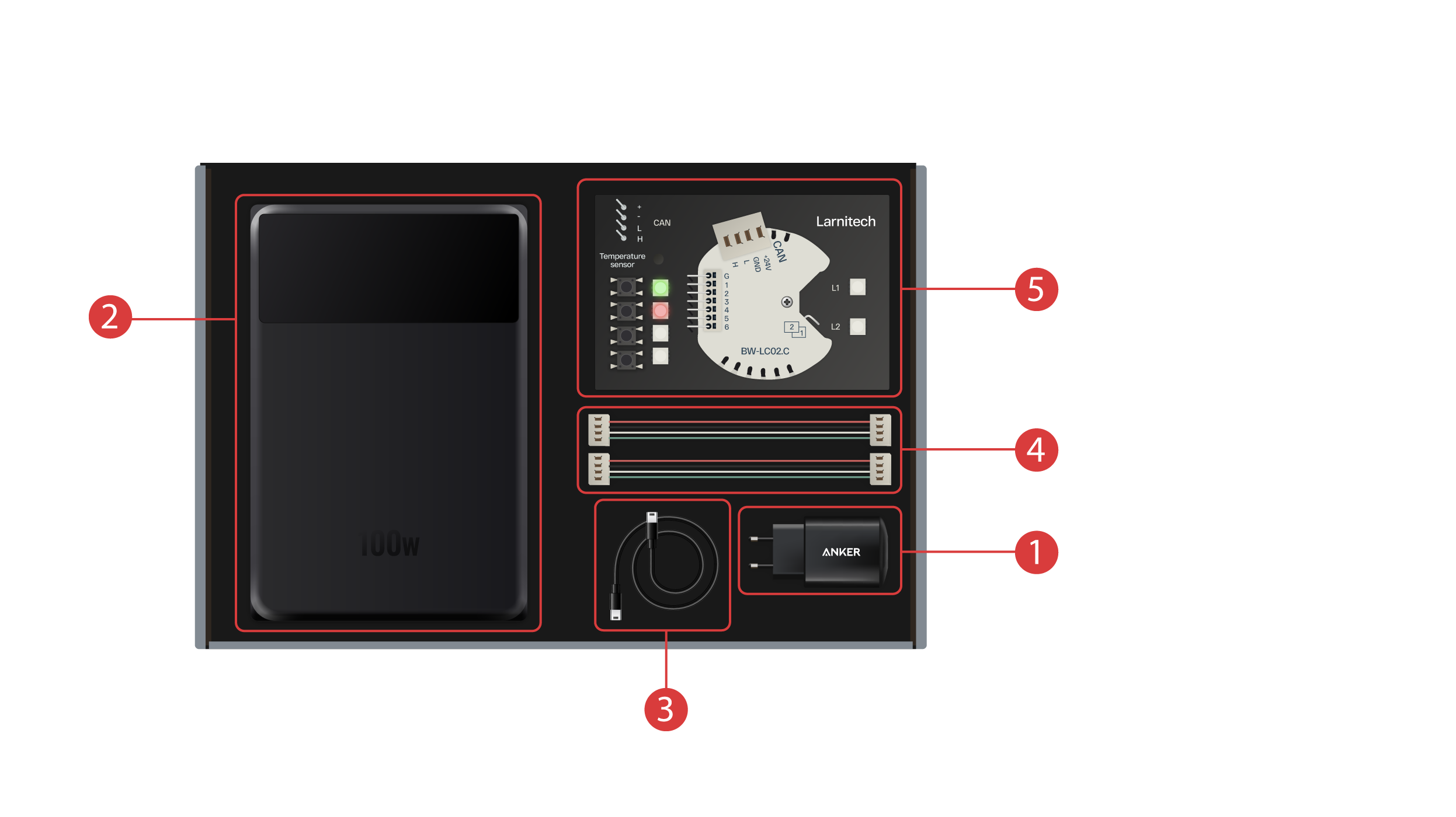
Krabice obsahuje následující položky:
① - Napájecí jednotka s portem USB typu C s podporou technologie Power Delivery;
② - Powerbanka s displejem a výstupním portem Type-C, kterou lze použít k napájení demonstračního kufru;
③ - Kabel typu C s indikátorem spotřeby energie;
④ - 2 kabely sběrnice CAN;
⑤ - Demonstrační deska s modulem BW-LC02 se 2 LED diodami, 4 tlačítky s podsvícením a připojeným teplotním čidlem.
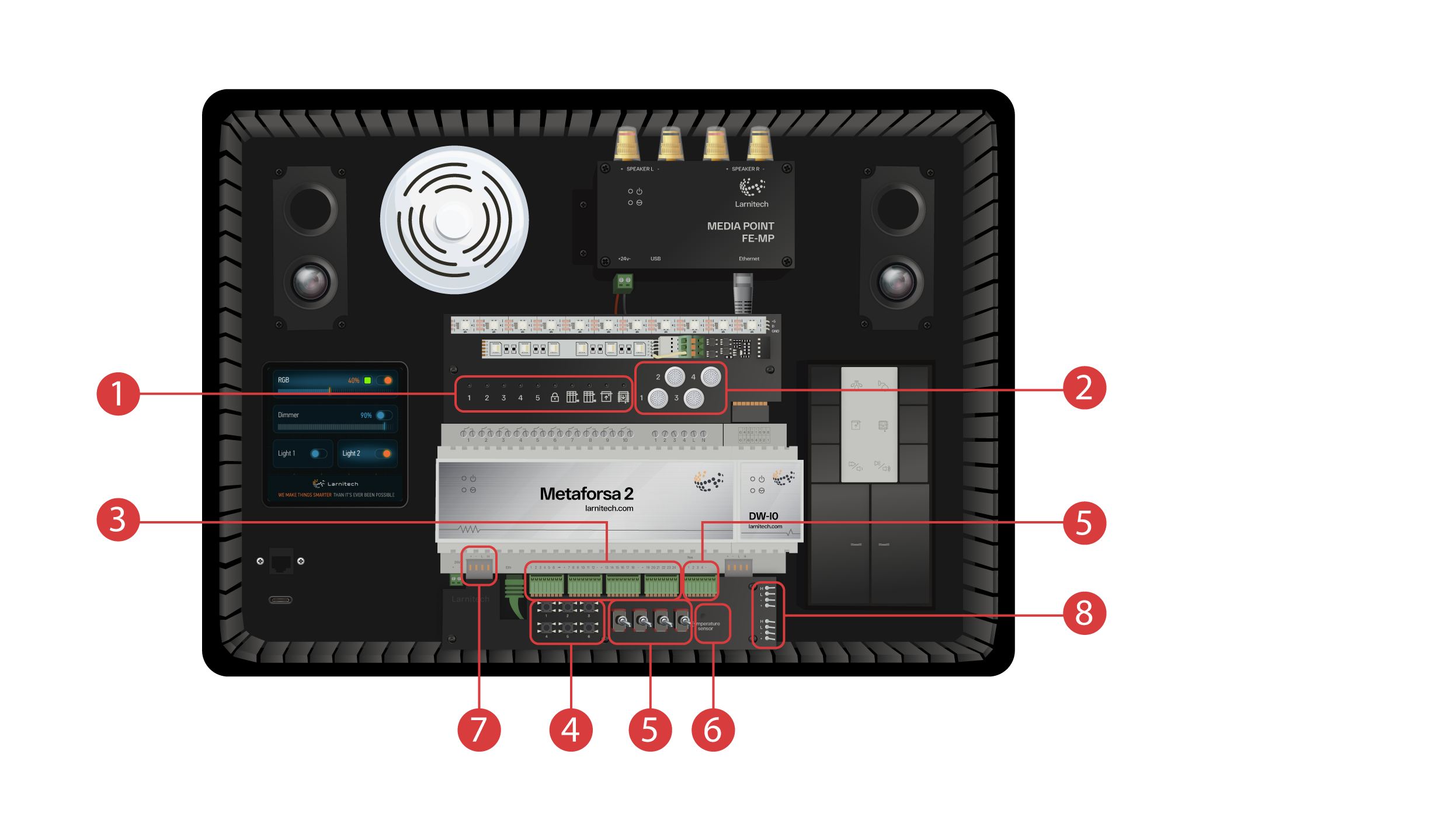
Předváděcí kufr obsahuje následující prvky: Modul 'Metaforsa 2'.
'Metaforsa 2' má:
① - 10 reléových kanálů s připojenými kontrolkami LED, které indikují jejich aktuální stav;
② - 4 stmívatelné kanály, ke kterým jsou připojena stmívatelná LED světla;
③ - 24 vstupních kanálů, k nimž je připojeno 6 tlačítek ④ a 4 přepínače ⑤ pro imitaci různých senzorů;
⑥ - Vstupní kanály pro teplotní čidla s jedním připojeným čidlem;
⑦ - Sběrnice CAN pro připojení dalších zařízení. K němu jsou připojeny další moduly demonstrační skříně a 2 porty ⑧ pro připojení externích zařízení;
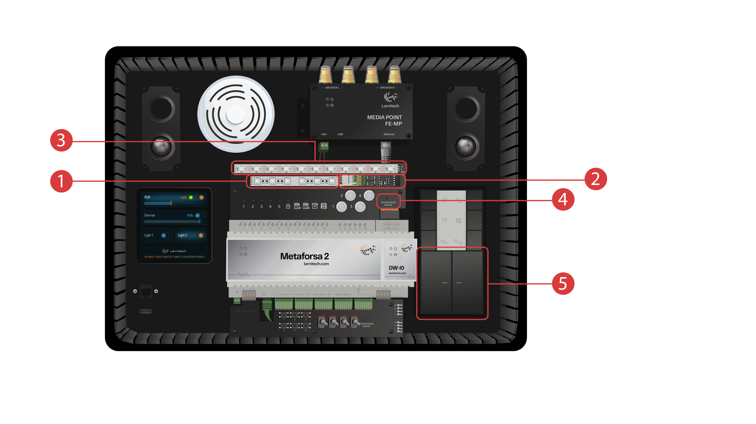
Modul DW-IO
Tento modul má 14 univerzálních vstupních/výstupních kanálů, ke kterým jsou připojeny následující položky:
① - 4 kanálový RGBW pásek, připojený přes proudový zesilovač AMP5V-4 ②;
③ - Pásek s adresovanými světly LED. Každé z těchto LED světel může svítit vlastní barvou;
④ - Snímač teploty;
⑤ - Dvě tlačítka s podsvícením.
Předváděcí kufřík obsahuje také následující:
① - a Media Point FE-MP ② se dvěma reproduktory;
③ - Senzor CW-CO2 šest v jednom, který měří: Úroveň pohybu, Osvětlení, Teplotu, Vlhkost, Úroveň CO2 a který má infračervený vysílač;
④ - 4 palcový senzorový panel LCP4, který může zobrazovat buď běžné rozhraní, nebo rozhraní přizpůsobené pro nástěnné panely;
Uvnitř skříně se nachází tlačítkový ovládací modul BW-SW24, ke kterému je připojena šesti tlačítková 24 voltová klávesnice JUNG ⑤;
A router Wi-Fi, který lze připojit k internetu buď přes ethernetový port na předním panelu skříně ⑥, nebo přes dostupnou síť Wi-Fi;
Pro napájení slouží port typu C ⑦, který je umístěn na předním panelu.
Veškeré vybavení instalované v předváděcím kufříku je napájeno napětím 20 V, které je pro uživatele naprosto bezpečné.
Připojte napájecí kabel a kabel Ethernet. Pokud nemáte možnost připojení přes Ethernet, později v tomto videu ukážeme, jak připojit vestavěný směrovač k síti Wi-Fi.
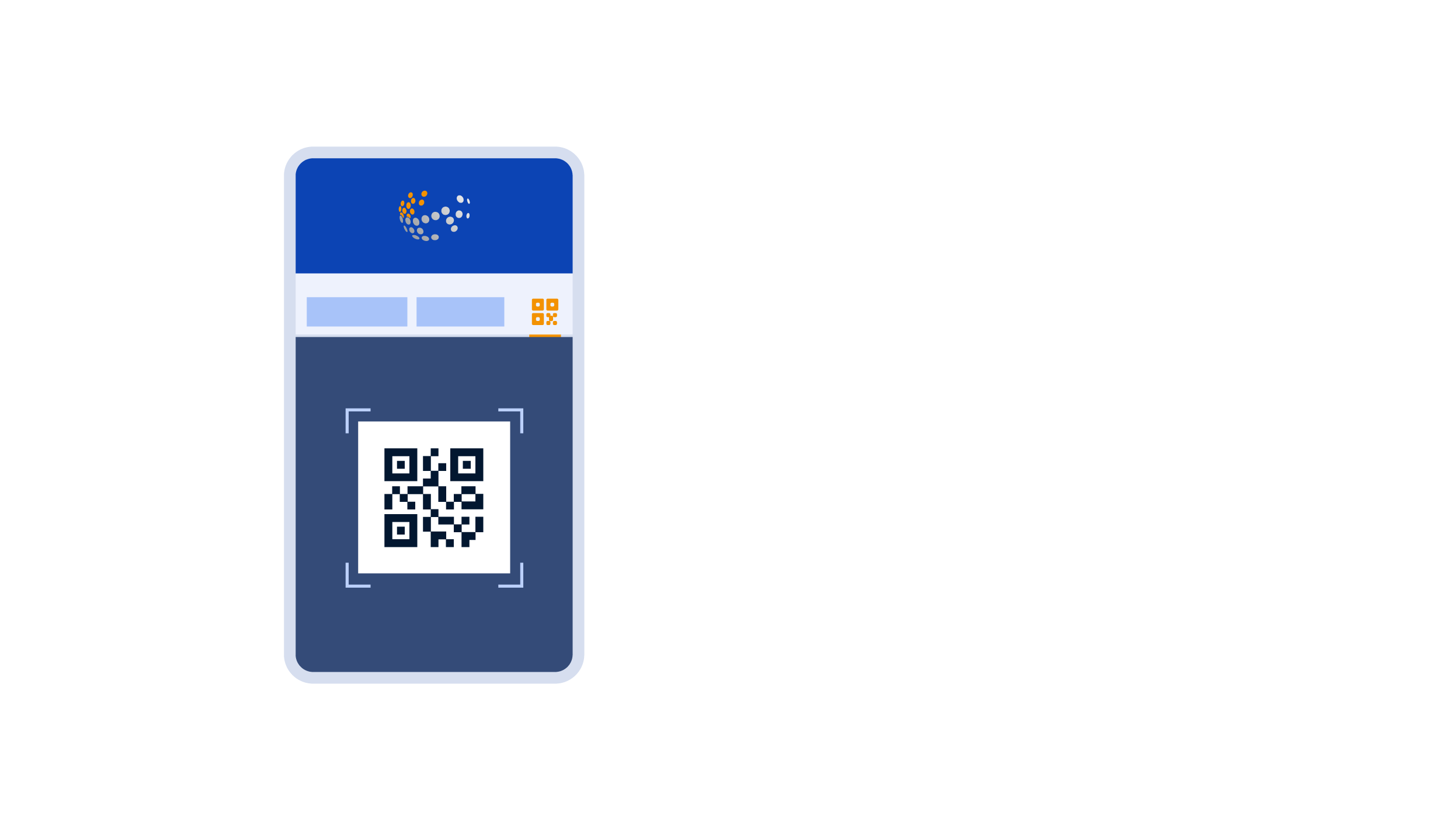
Abyste mohli pokračovat, je třeba do chytrého telefonu nebo tabletu nainstalovat aplikaci Larnitech. Stačí naskenovat první QR kód z horní části kufru.
Pokud po instalaci a spuštění aplikace nedojde k automatickému navázání připojení, je třeba se připojit k síti Wi-Fi "Larnitech_case_5G" pomocí Vašeho mobilního zařízení. Poté spusťte aplikaci a naskenujte první QR kód v části "Připojení".
Pokud předváděcí sada není připojena k internetu, může být nutné vypnout přenos dat na mobilním zařízení.
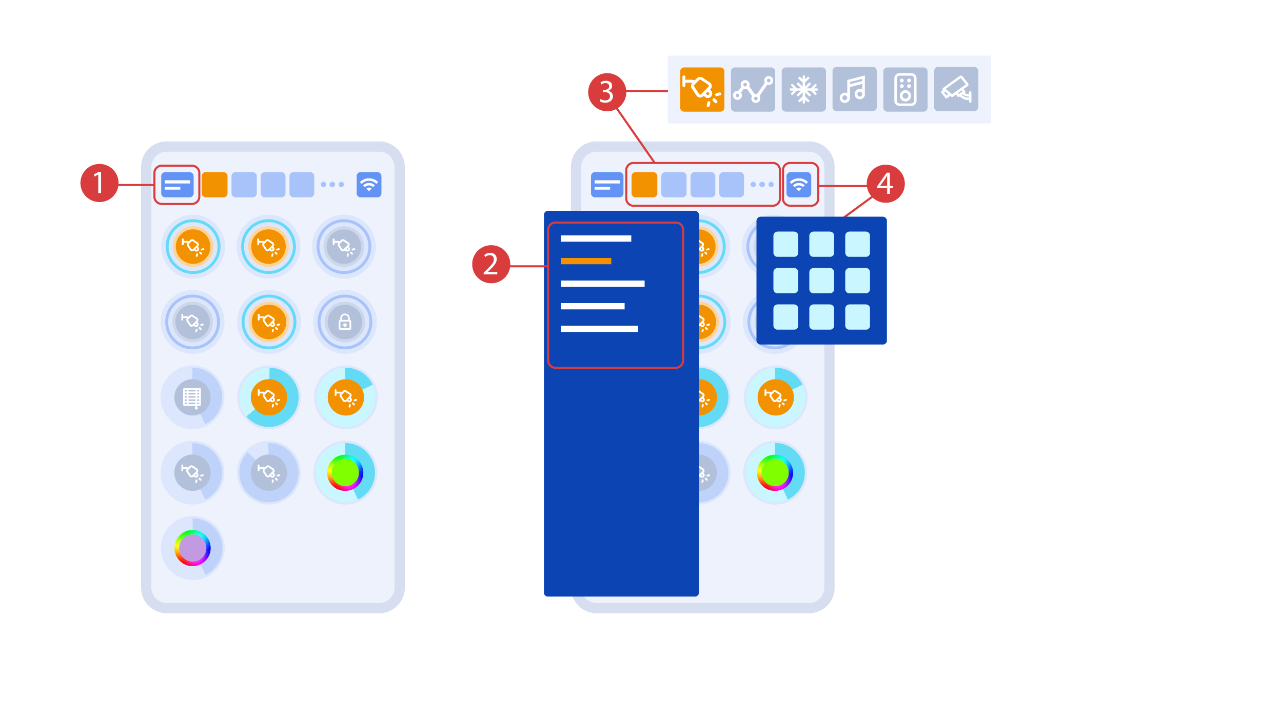
Hlavní obrazovka aplikace obsahuje několik klíčových prvků. V levém horním rohu se nachází nabídka "výběr oblasti" ①.
Chcete-li spravovat jednu z dostupných oblastí, stačí na ni kliknout ②.
Dále jsou zde ikony, které umožňují vybrat spouštěče, senzory, klimatizaci, multimédia, dálkové ovládání a kamery ③. V pravém rohu se nachází ikona pro další nabídku ④. Uvnitř ikony můžete také vidět stav aktuálního připojení.
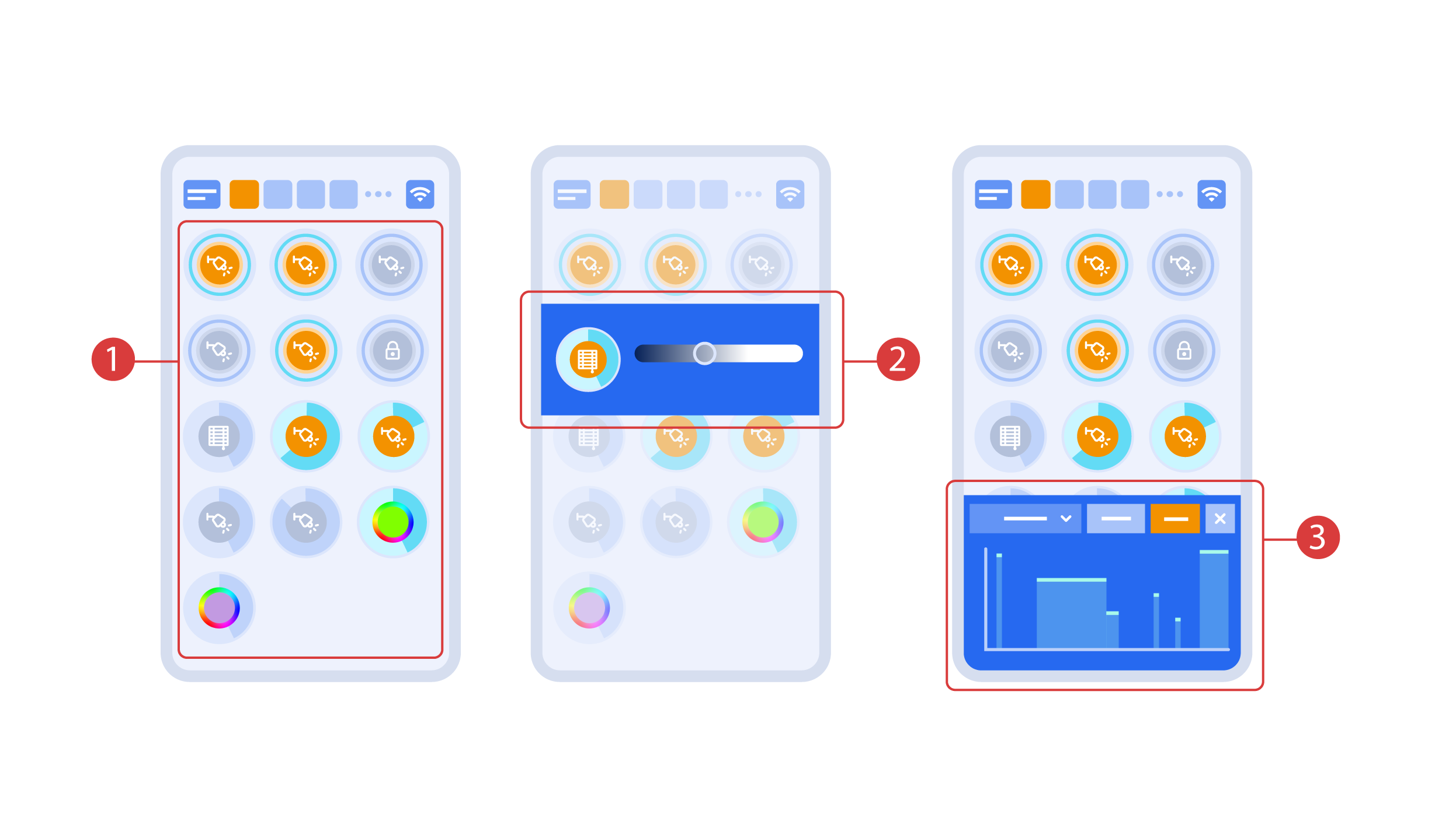
Turning the executors ① on or off is done with a simple click. In order to change the level of lighting ②, color of lights or the position of the blinds, use a double click. In order to access the status history ③ of this executor or sensor, press and hold the icon for one second.
A short press of the physical buttons on the panel turns the light on or off. Press and hold the button to change the light brightness.
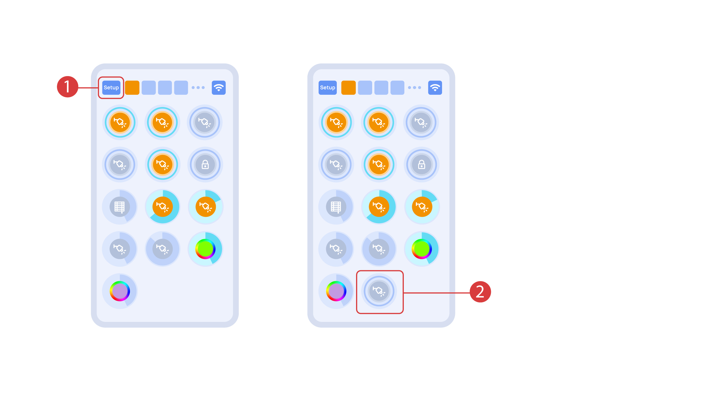
In order to demonstrate the Plug and Play function, we open the executors in the Setup area ① and connect the module to the CAN bus. The system automatically detects the new module and adds it to the ‘Setup’ area, ② where we are able to control the new module instantly.
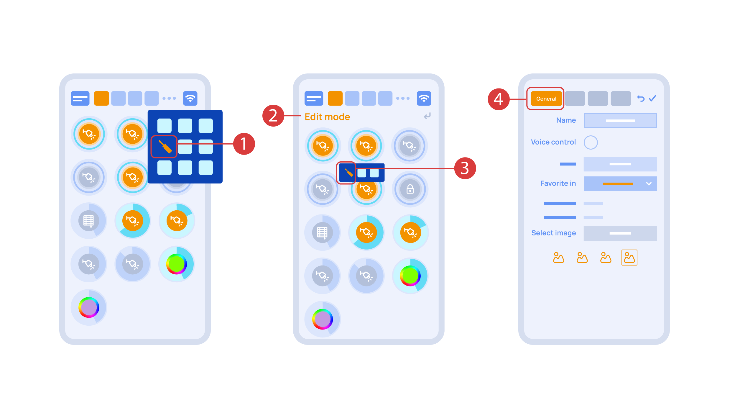
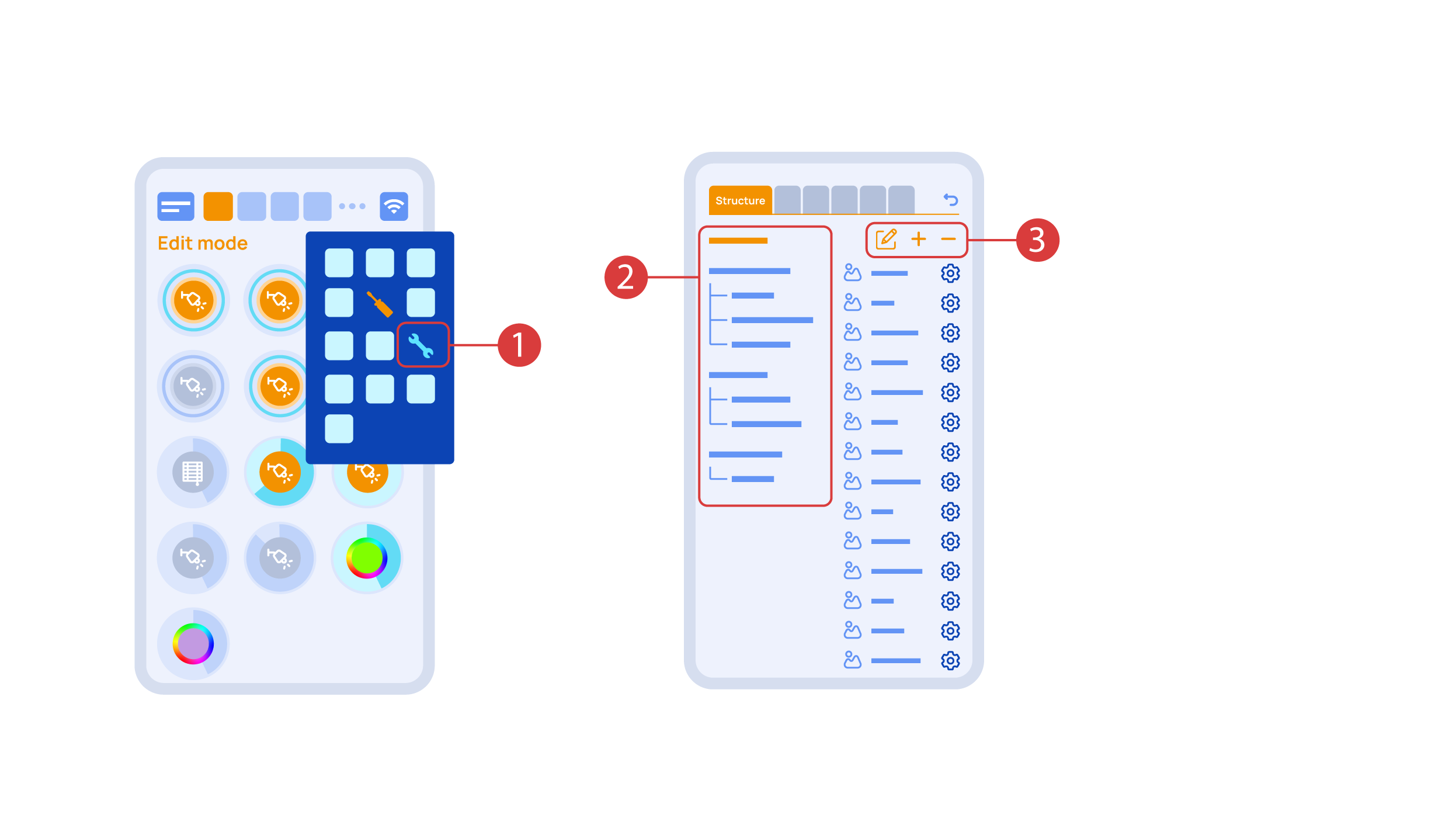
Now we can set up these executors. In order to do this, enter the additional menu ① and activate the edit mode, by pressing the appropriate icon .
Now we are in the edit mode ②, which can be seen from the appropriate notification in the top part of the screen. In this mode, when we press and hold an icon, we can move it among other elements and place it into another Room by placing it in the Area-choosing Menu and then choosing the area that we need. A long press ③ of the element starts the menu, from which we set up the current element.In the ‘General’ ④ section we can change the name of the element, add a voice command for it, change an icon or add the element to ‘Favorites’.
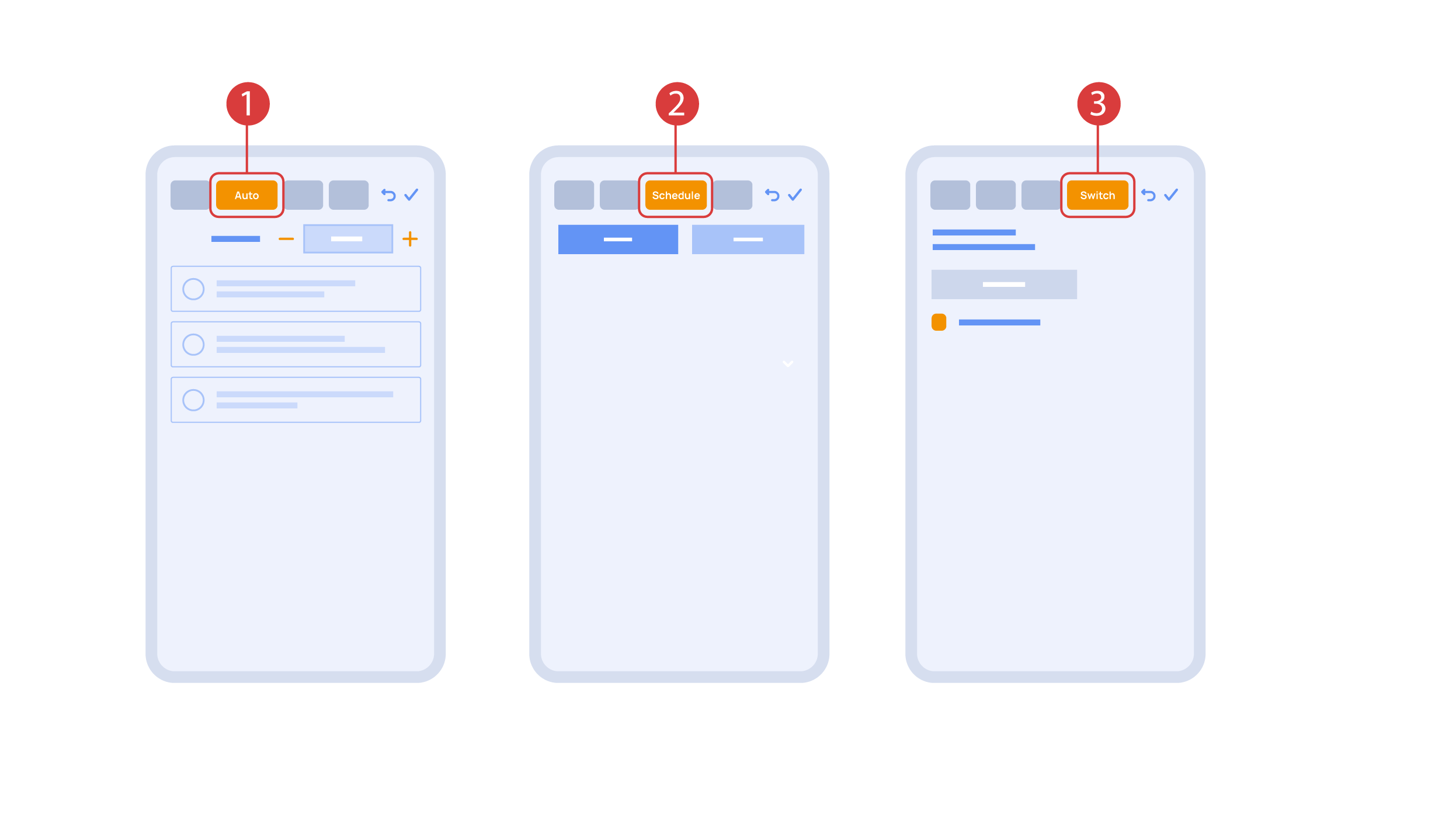
‘Auto’ section ① lets us activate the automation with a few clicks, as well as set up its parameters.
In the ‘schedule’ section ②, you can determine the schedule when the given element will turn on or off, including by using the time of the setting and rising of the sun.
The ‘Switches’ tab ③ lets you bind a button to control the executor.
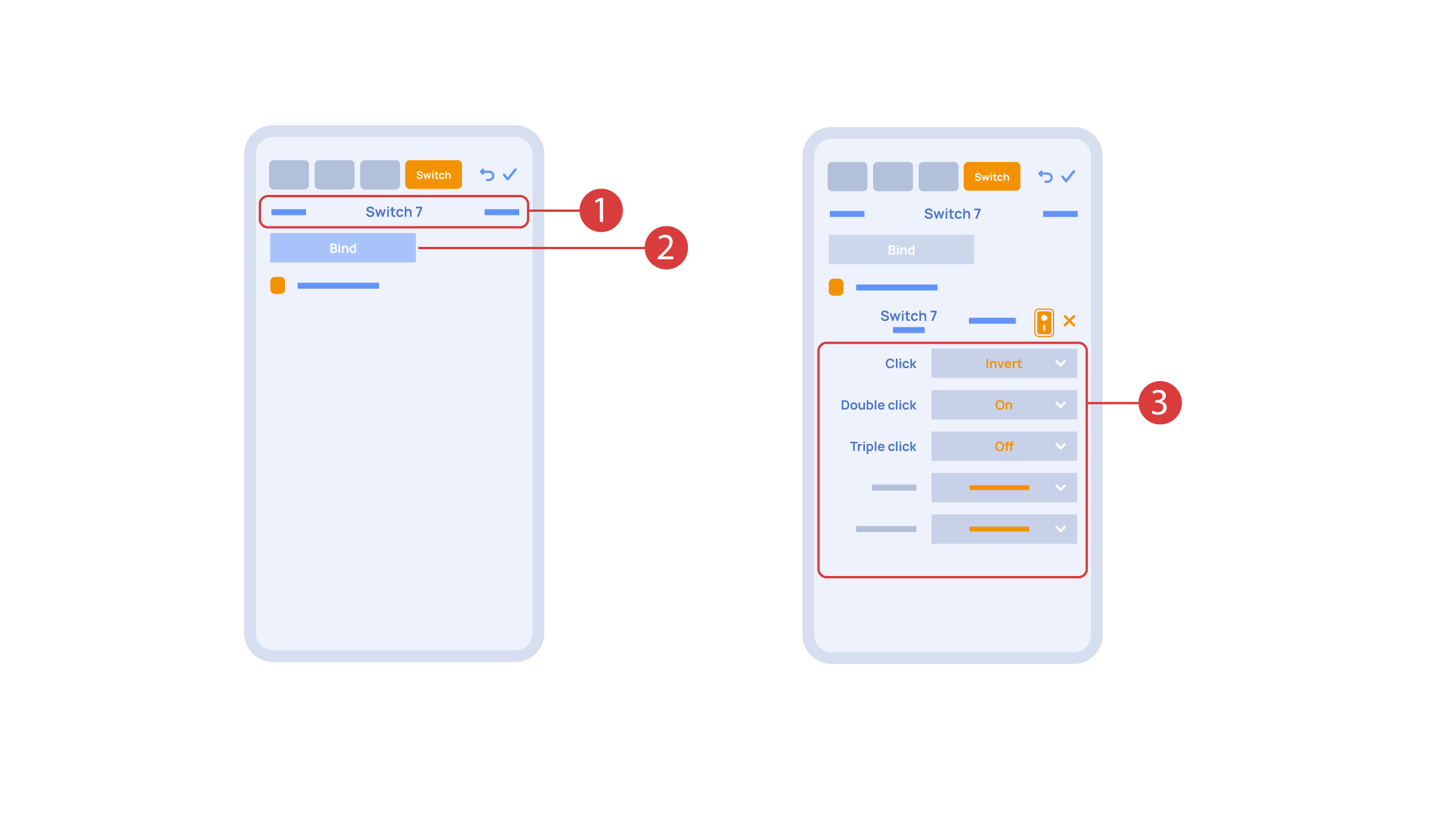
In order to do this, ① we press the button we need to bind. The system displays it, after which we press ‘Bind’② and save the changes. Now this button controls the executor
The ‘Switches’ tab ③ also features additional button setup options. For example, we can program the executor to be controlled with a double or triple click of a button, as well as define an action performed by this, for example ‘only turning on’ or ‘only turning off’ an executor. In this case we are setting up the button to do the following: one click will cause the lamp to toggle, a double click will turn it on and a triple click will turn it off. In this way a single button can perform up to five different actions.
Let’s also set up basic automation of turning an executor on or off with the help of a motion sensor.
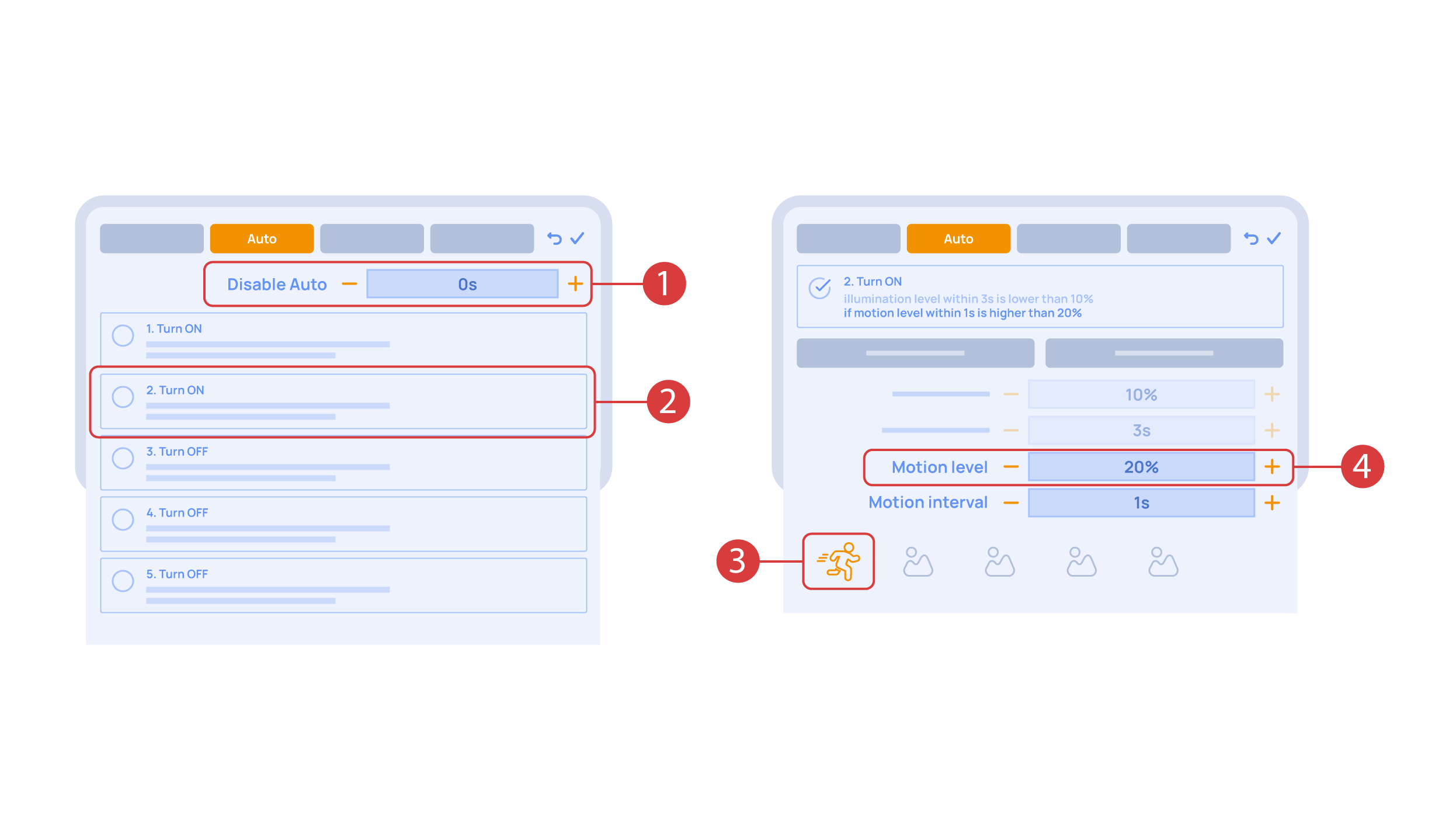
The ‘Auto period’ ① option sets the time for which the automation is disabled after an executor is manually controlled.For our demonstration purposes, we will set it to zero.
Then we will activate the automation ② to turn on the executor when motion is detected. We choose the motion sensor ③ and the level of motion ④. We can also choose a light sensor and its parameters.
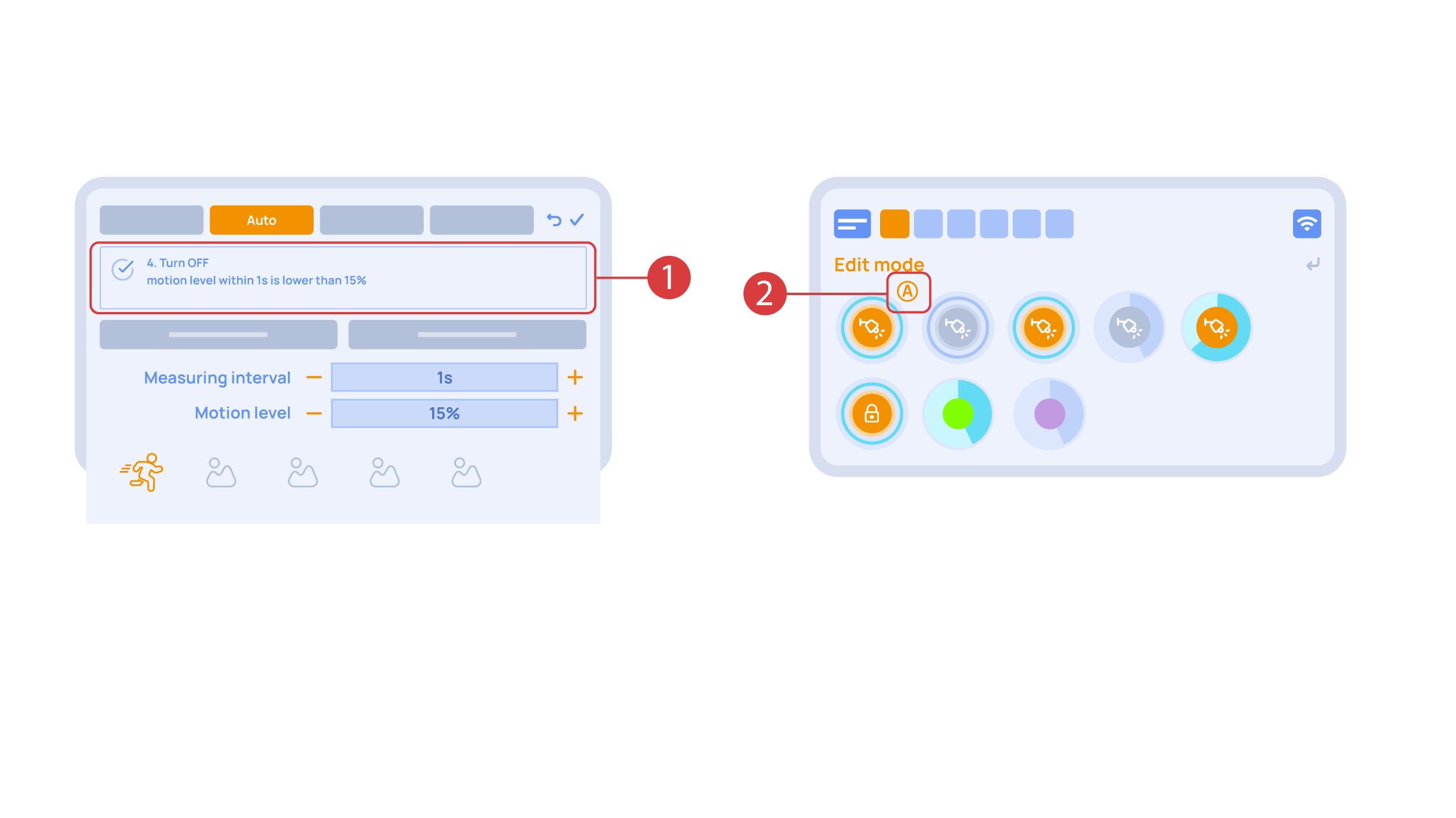
Now we will activate turning off ① of an executor if there is no motion: we choose the same sensor, set a lower threshold and a minimal time.Save the changes.
The extra ‘A’ icon ② will be added to the executor icon, meaning that automation has been set up for it. Now the lamp will be turned on when motion is detected and instantly turned off when no motion is detected.
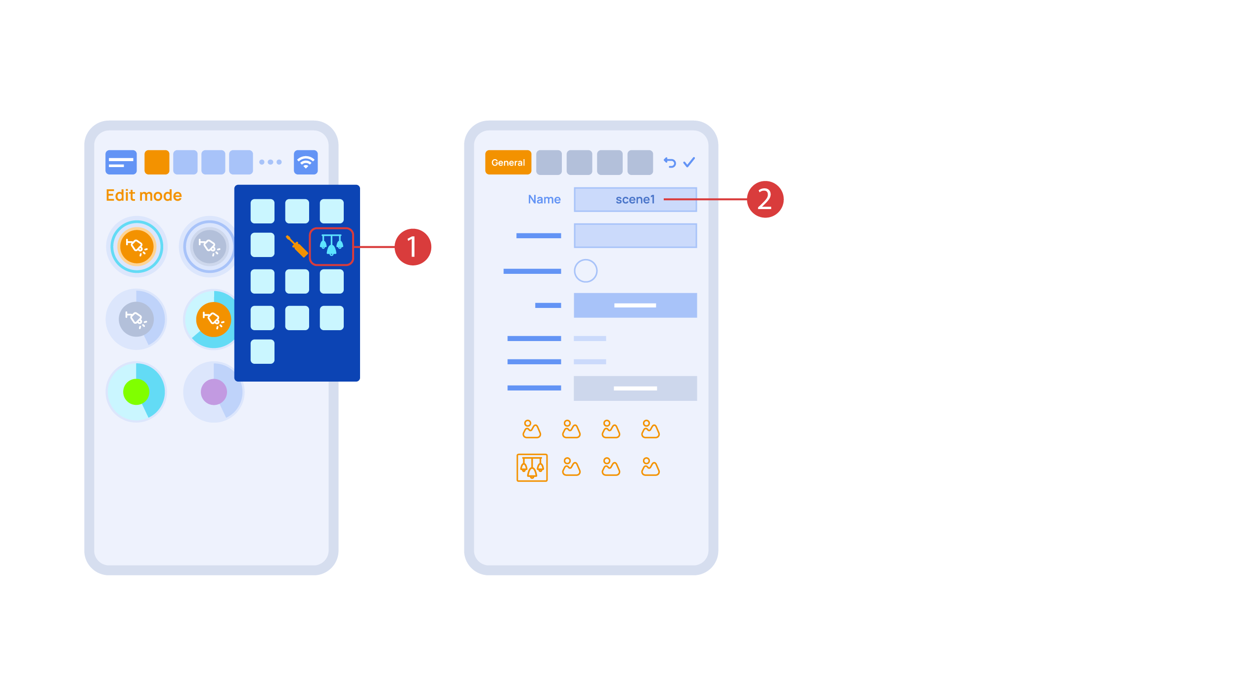
Let’s create a light scheme. For this we need to select the appropriate item in the additional menu ①. Give the light scheme a name ②.
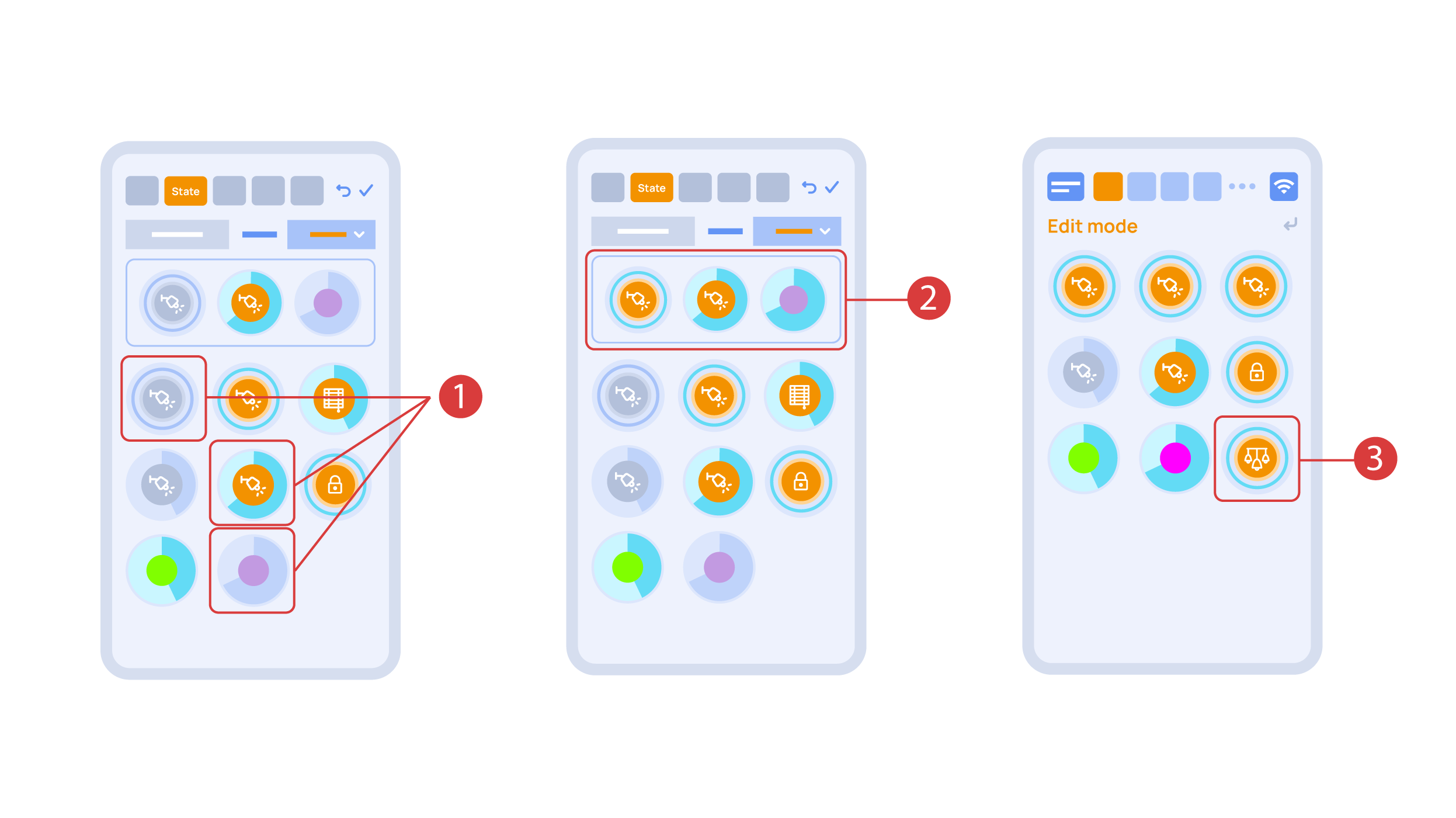
In the ‘State’ tab, use a long press to add the lights we want to use into the light scene ① and set up their state ②. ‘Auto’, ‘Schedule’, ‘Switch’ tabs are the same for all the executors.
Save the changes and we are able to use the newly-created light scheme ③ immediately.
While you are in the Edit Mode, there is a ‘Setup’ ① icon in the additional menu.
Here in the ‘Structure’② tab we can see all the areas.
We can create new ones ④, rename them and move the elements around.
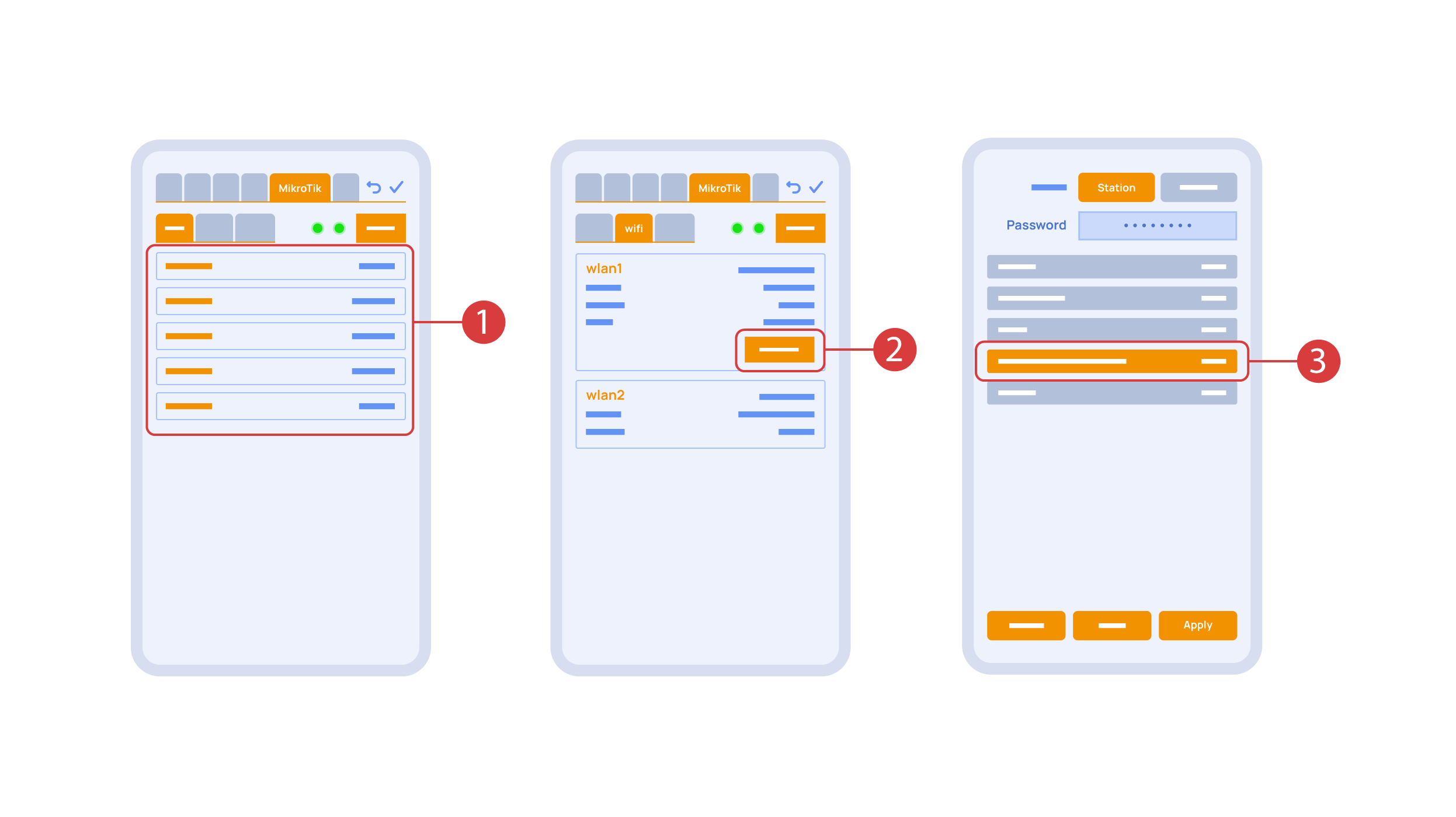
In the ‘Mikrotik’ tab ① you can see the current parameters of your router, which you can also connect to your local Wi-Fi network.
In order to do this, enter the Wi-Fi sub-menu, click the wlan1 interface configuration ②, after which choose the ‘station’ mode, choose a Wi-Fi network out of the list ③ of available ones and enter the connection password.
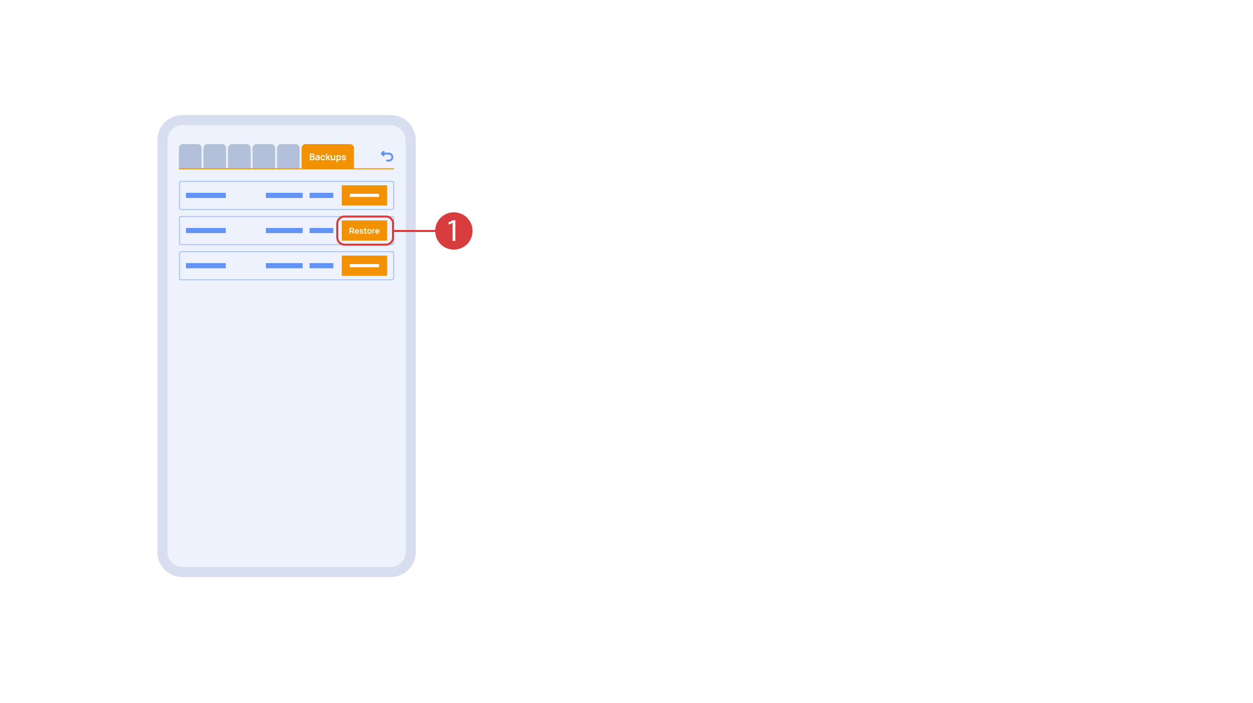
In the ‘Backups’ tab ① you can see the list of saved configurations, which can be restored if necessary.
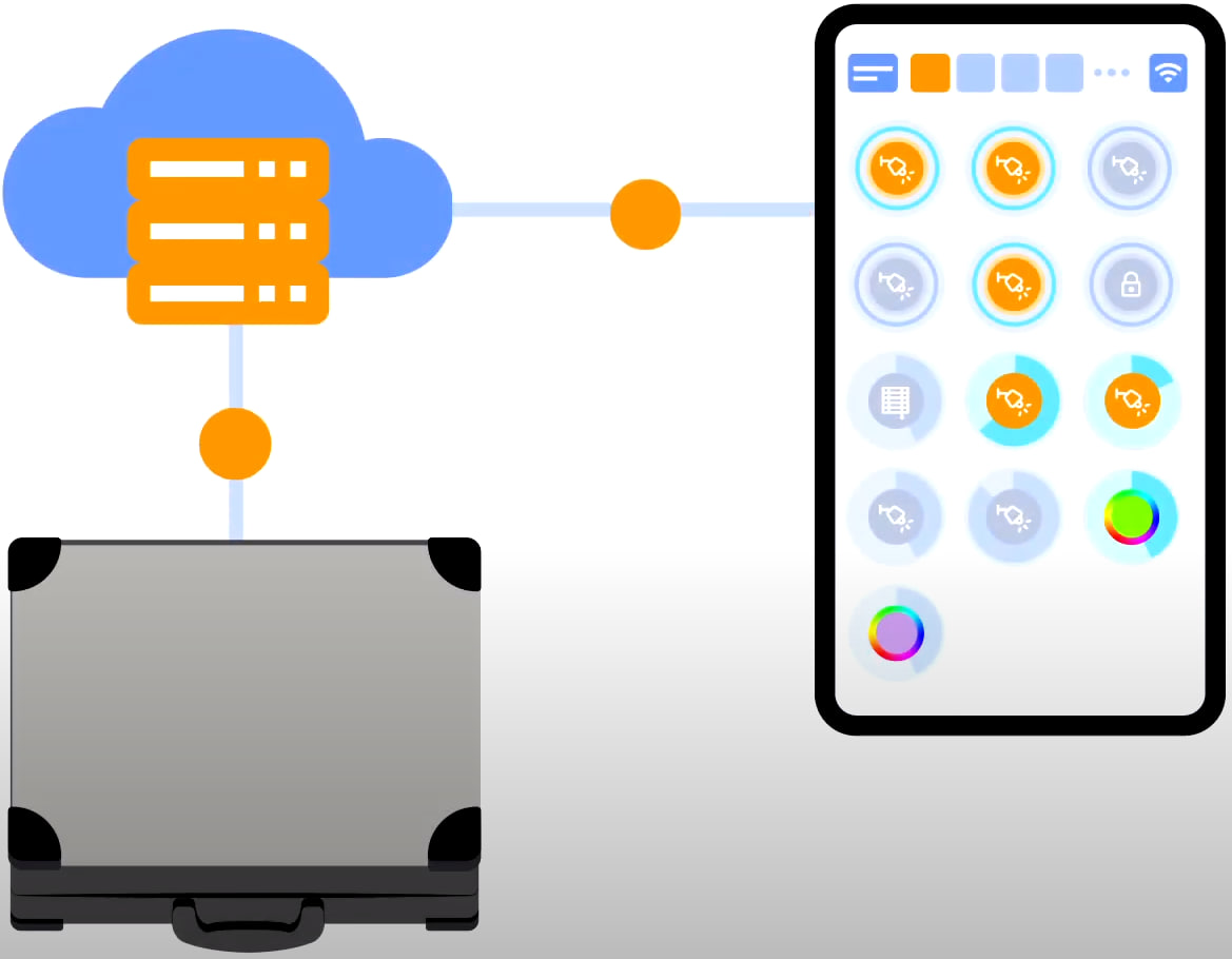
For cloud access to the device, you do not need any extra settings. The app detects the absence of the system in your local network and automatically establishes the connection via the cloud.
We thank you for watching this tutorial! If you have questions or need extra help, please do not hesitate to refer to our technical support team. See you in the next episodes!