Greitas paleidimas / išpakavimas.
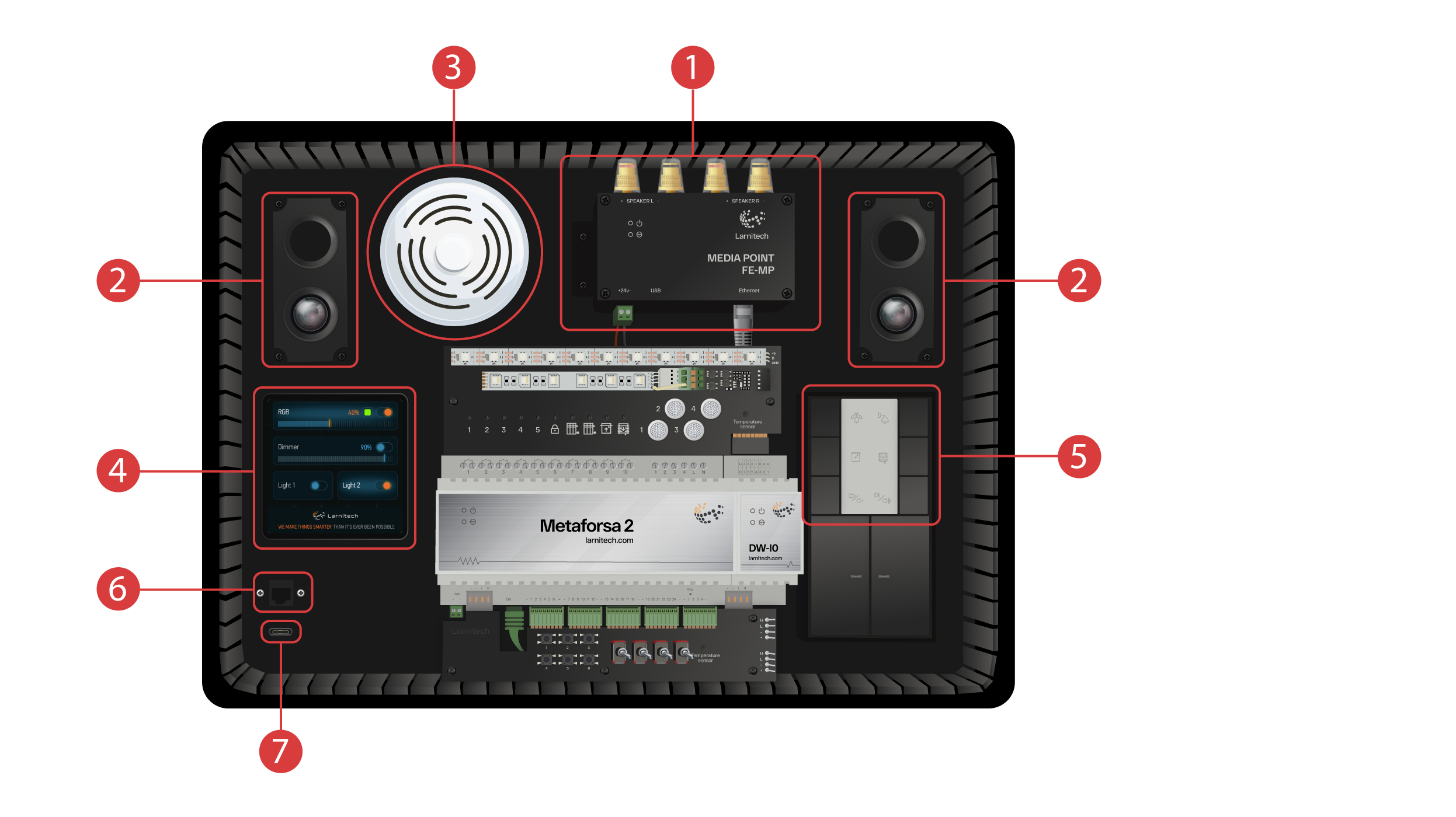
Sveikiname visus mūsų kanalo lankytojus! Šis vaizdo įrašas yra vadovas, kaip greitai ir be vargo įdiegti "Larnitech" sistemą. Konfigūracija bus atliekama parodomojo lagamino pagalba. Mokomąjį rinkinį sudaro parodomasis lagaminas ① ir dėžutė su keliais papildomais priedais ②.
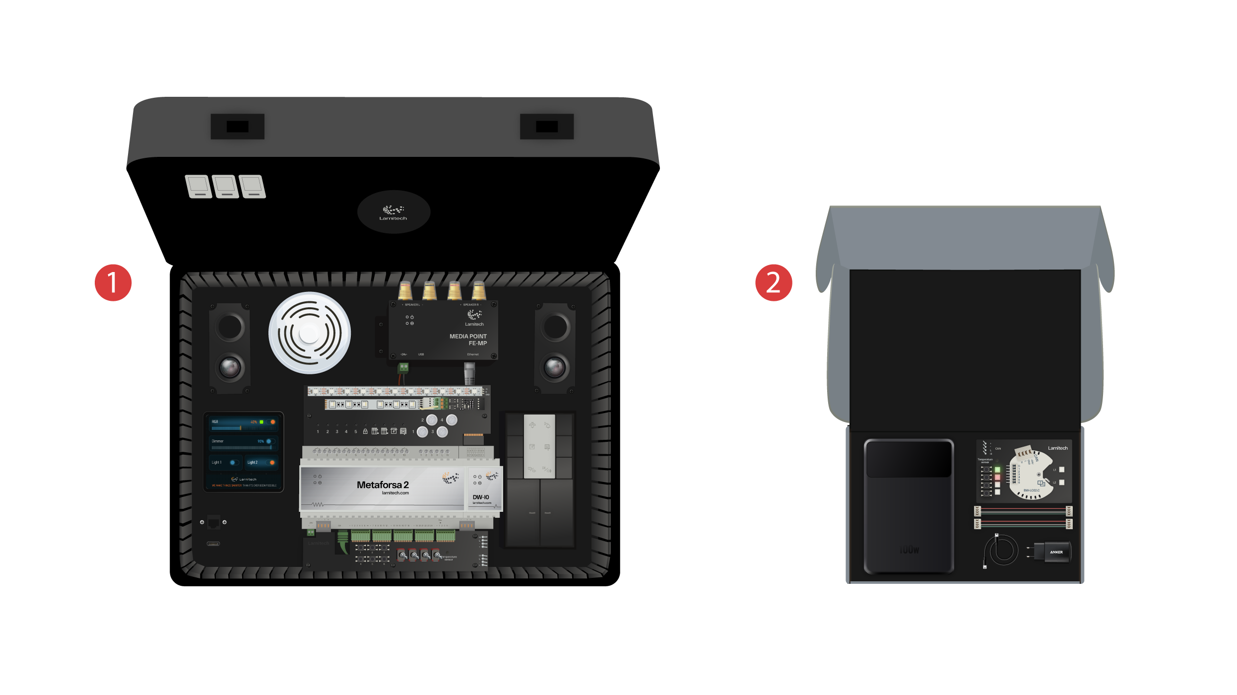
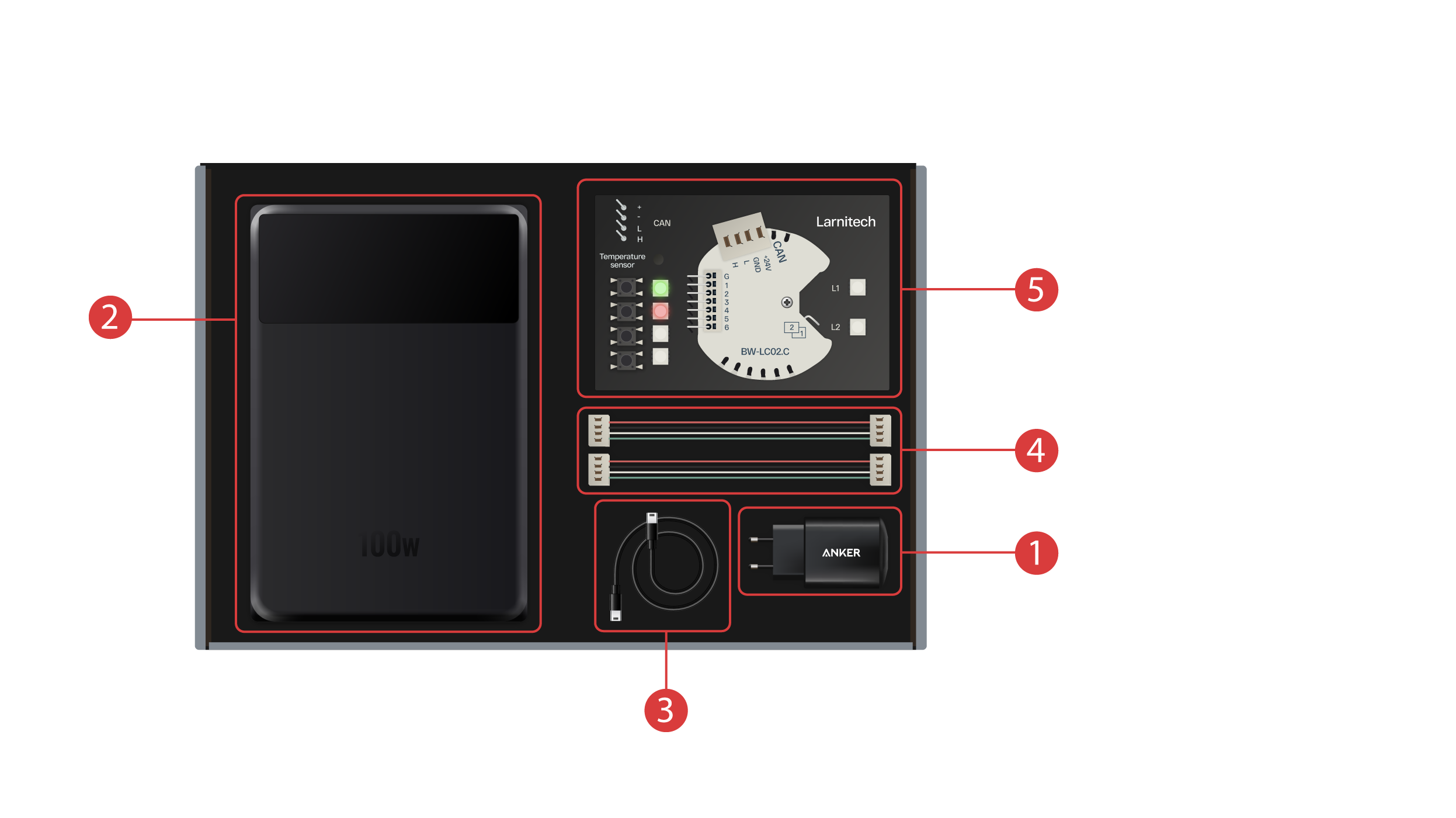
Dėžutėje yra:
① - Maitinimo blokas su USB-C jungtimi, palaikantis Power Delivery technologiją;
② - Išorinė baterija su ekranu ir C tipo jungtimi, kurį galima naudoti parodomojo lagamino maitinimui;
③ - C tipo kabelis su energijos suvartojimo indikatoriumi;
④ - 2 CAN bus kabeliai;
⑤ - Demonstracinė plokštė su BW-LC02 moduliu, prie kurio prijungtos 2 LED lemputės, 4 mygtukai su foniniu apšvietimu ir temperatūros jutiklis.
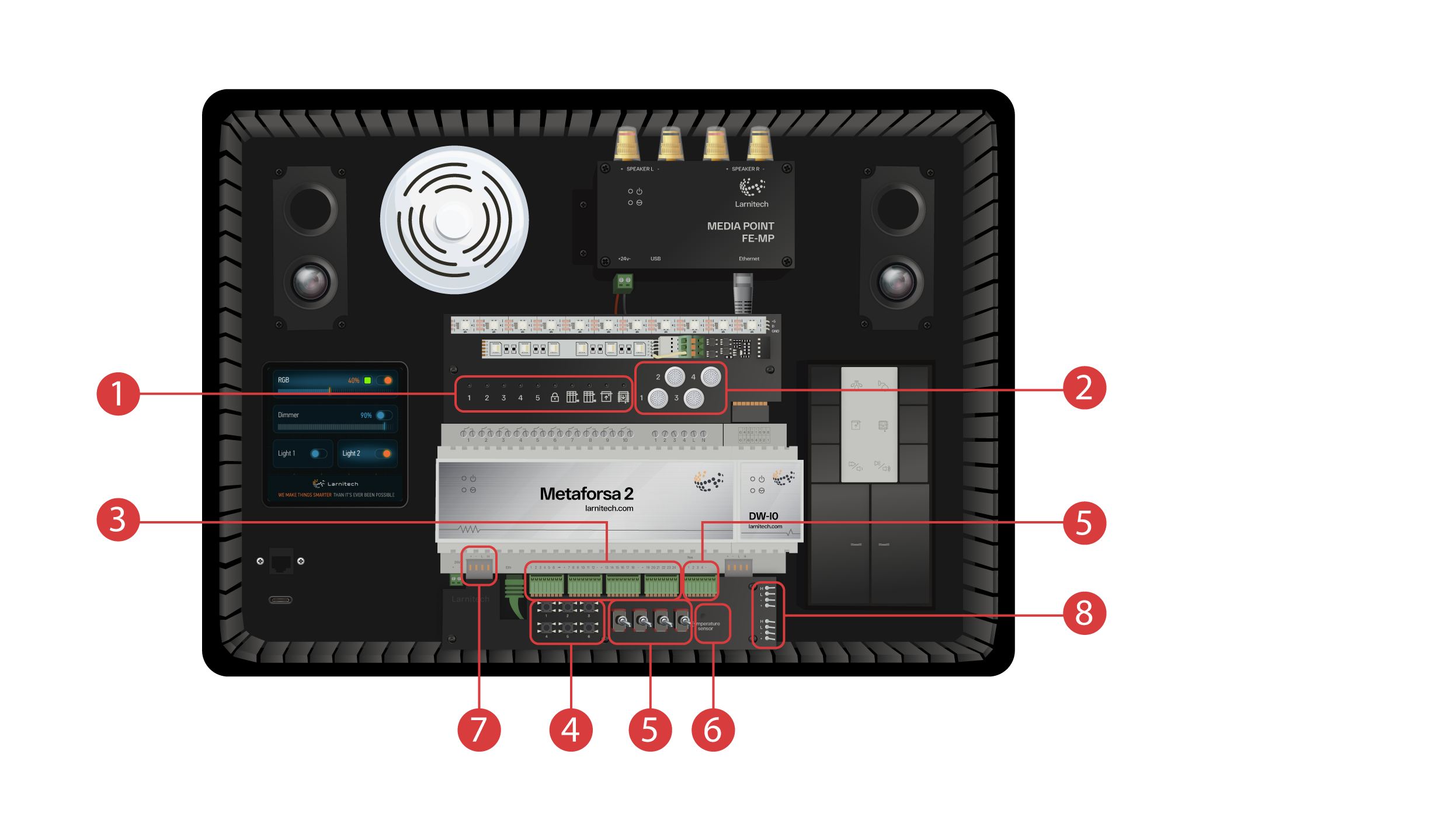
Demonstracinį lagaminą sudaro šie elementai: "Metaforsa 2" modulis.
"Metaforsa 2" turi:
① - 10 rėlinių kanalų, su prie jų prijungtomis LED lemputėmis, rodančiomis jų esamą būseną;
② - 4 reguliuojamo ryškumo kanalai, prie kurių prijungtos reguliuojamo ryškumo LED lemputės;
③ - 24 įvesties kanalai, prie kurių prijungti 6 mygtukai ④ ir 4 jungikliai ⑤, siekiant imituoti įvairius jutiklius;
⑥ - Temperatūros jutiklių įvesties kanalai, prie kurių prijungtas vienas jutiklis;
⑦ - CAN bus papildomiems įrenginiams prijungti. Prie jo prijungti kiti demonstracinio lagamino moduliai ⑧ , taip pat 2 jungtys išoriniams įrenginiams prijungti.
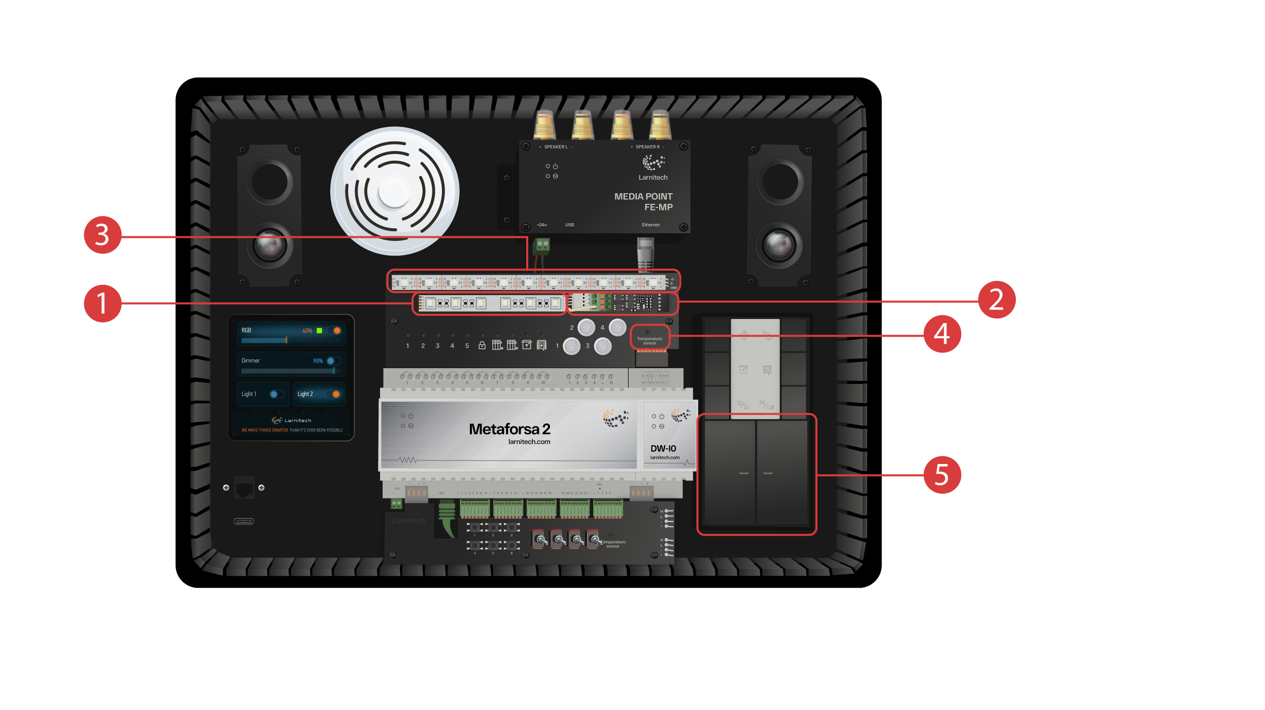
DW-IO modulis
Šis modulis turi 14 universalių įvesties / išvesties kanalų, prie kurių prijungti šie elementai:
① - 4 kanalų RGBW juosta, prijungta per AMP5V-4 ② srovės stiprintuvą;
③ - Juostelė su jai skirtomis LED lemputėmis. Kiekviena iš šių LED lempučių gali šviesti savo individualia spalva;
④ - Temperatūros jutiklis;
⑤ - Ir du mygtukai su foniniu apšvietimu.
Į parodomąjį lagaminą taip pat įeina:
① - un Media Point FE-MP con ② due altoparlanti;
③ - Un sensore CW-CO2 sei-in-uno, che misura: Livello di movimento, Illuminazione, Temperatura, Umidità, Livello di CO2 ed è dotata di un trasmettitore ad infrarossi;
④ - un pannello sensore da 4 pollici LCP4 che può visualizzare un'interfaccia normale o un'interfaccia adattata ai pannelli a parete;
All'interno della valigetta è presente un modulo di controllo a pulsanti BW-SW24 a cui è collegata una tastiera JUNG a sei pulsanti da 24 volt ⑤.
E un router Wi-Fi, che può essere collegato ad Internet tramite una porta Ethernet ⑥ sul pannello frontale del case o tramite una rete Wi-Fi disponibile.
Per l'alimentazione è presente una porta di tipo C ⑦, situata sul pannello frontale.
Tutte le apparecchiature installate nella valigetta dimostrativa sono alimentate a 20 Volt, in modo assolutamente sicuro per l'utente.
Collegamento del cavo di alimentazione e del cavo Ethernet. Se non si ha la possibilità di connessione via Ethernet, più avanti in questo video mostreremo come collegare il router integrato alla rete Wi-Fi.
Per procedere, è necessario installare l'applicazione Larnitech sul proprio smartphone o tablet. È sufficiente scansionare il primo codice QR presente nella parte superiore della valigetta.
Se dopo l'installazione e l'avvio dell'app la connessione non viene stabilita automaticamente, è necessario collegarsi alla rete Wi-Fi "Larnitech_case_5G" con l'aiuto del proprio dispositivo mobile. Quindi avviare l'app e scansionare il primo codice QR nella sezione "Connessioni".
Potrebbe essere necessario disattivare la connessione dati sul dispositivo mobile se il kit dimostrativo non è connesso ad Internet.

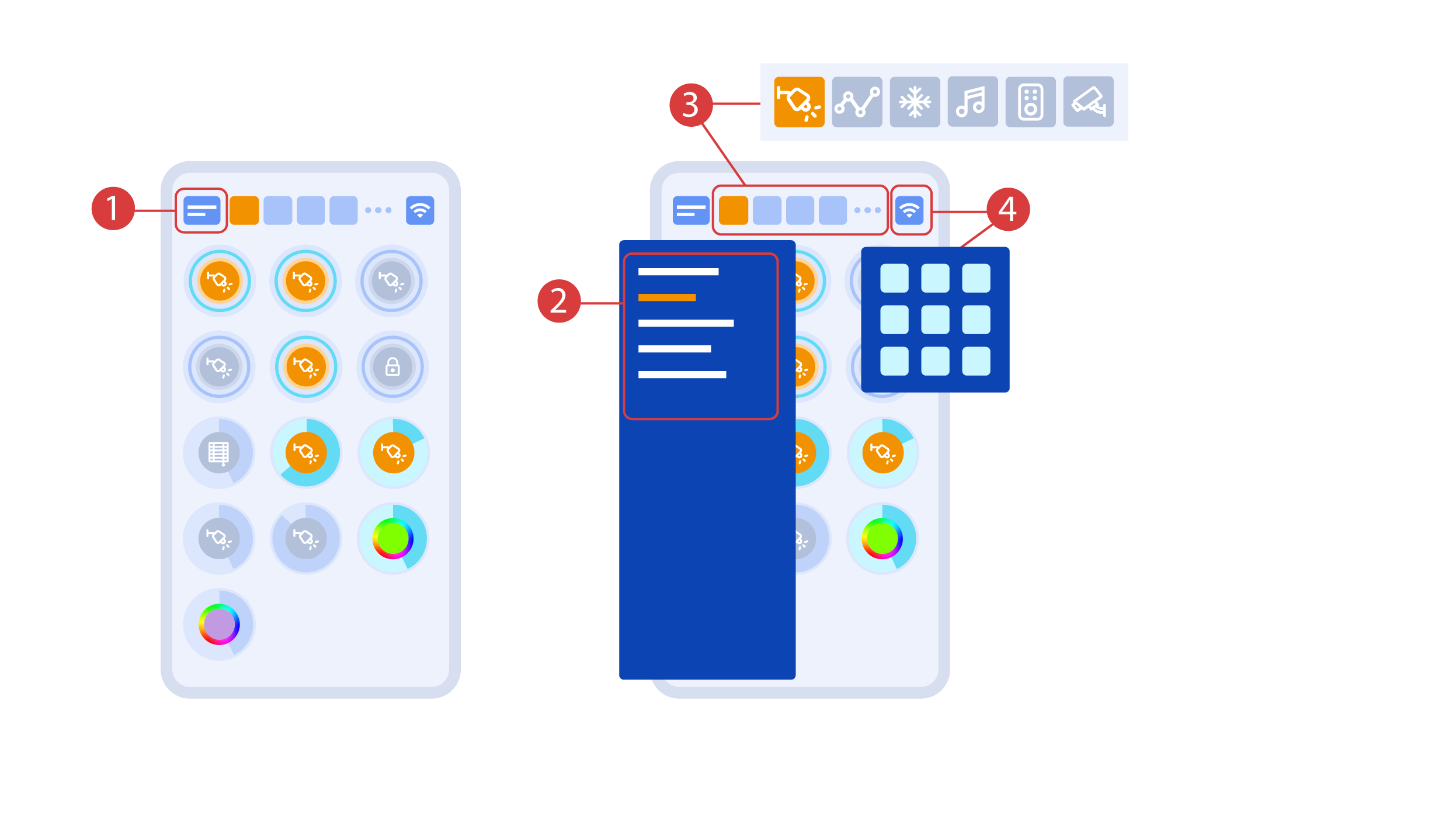
La schermata principale dell'app presenta diversi elementi chiave. Nell'angolo in alto a sinistra si trova il menu "Seleziona area" ①.
Basta fare clic su una delle aree disponibili per avviare la gestione di essa ②.
Ci sono anche delle icone che permettono di selezionare gli esecutori, i sensori, il meteo, i file multimedia, i telecomandi e le telecamere ③. Sull'angolo destro è presente un'icona per il menu aggiuntivo ④. All'interno dell'icona è possibile visualizzare anche lo stato della connessione attuale.
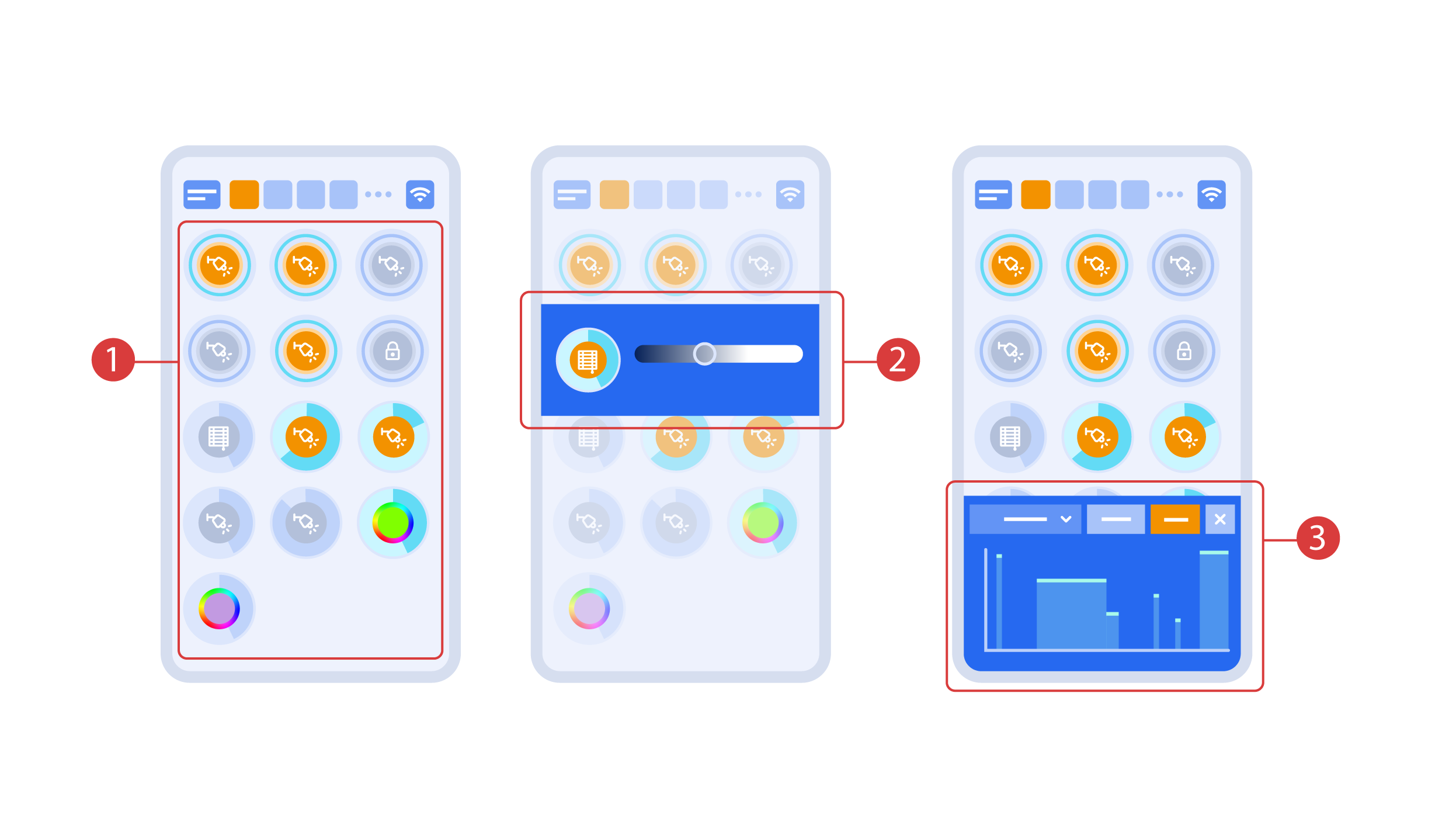
Per accendere o spegnere l’esecutore ① basta un semplice clic. Per modificare il livello di illuminazione ②, il colore delle luci o l’ombreggiatura, è sufficiente un doppio clic. Per accedere alla cronologia ③ dell’esecutore o del sensore, tenere premuta l'icona per un secondo.
Una breve pressione dei pulsanti fisici sul pannello accende o spegne la luce. Tenere premuto il pulsante per modificare la luminosità della luce.
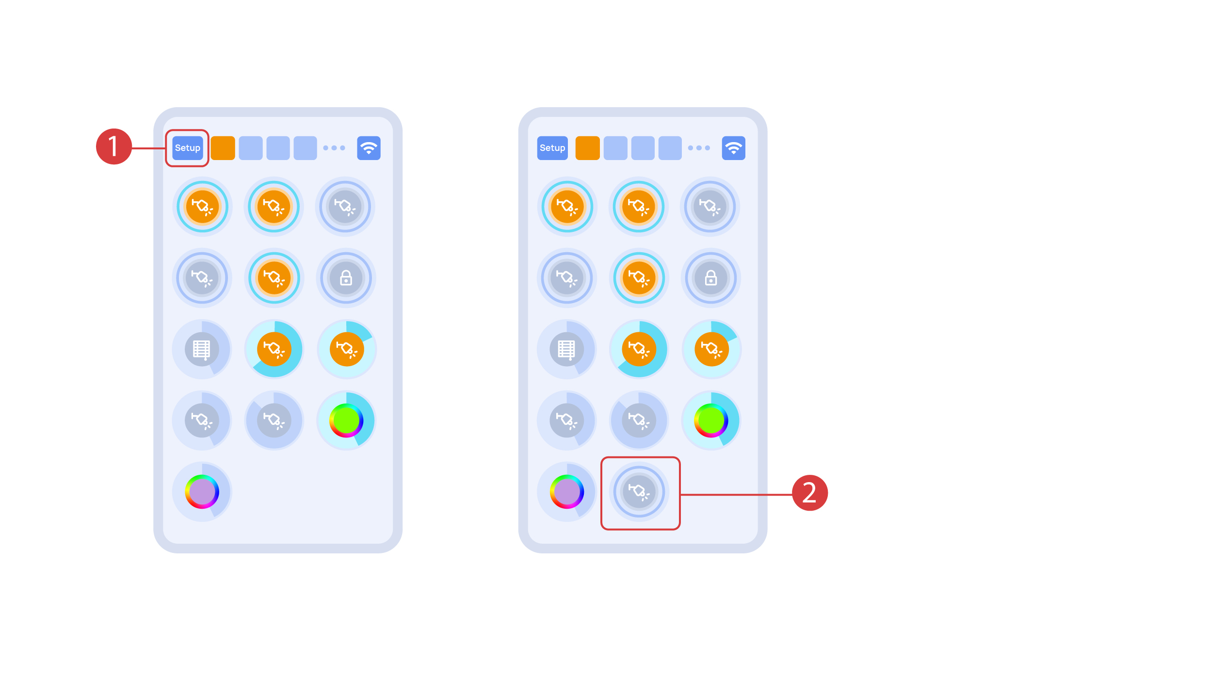
Per dimostrare la funzione Plug and Play, aprire l’esecutore nell'area di Configurazione ① e collegare il modulo al CAN bus. Il sistema rileva automaticamente il nuovo modulo e lo aggiunge all'area di "Configurazione" ②, dove è possibile controllarlo immediatamente.
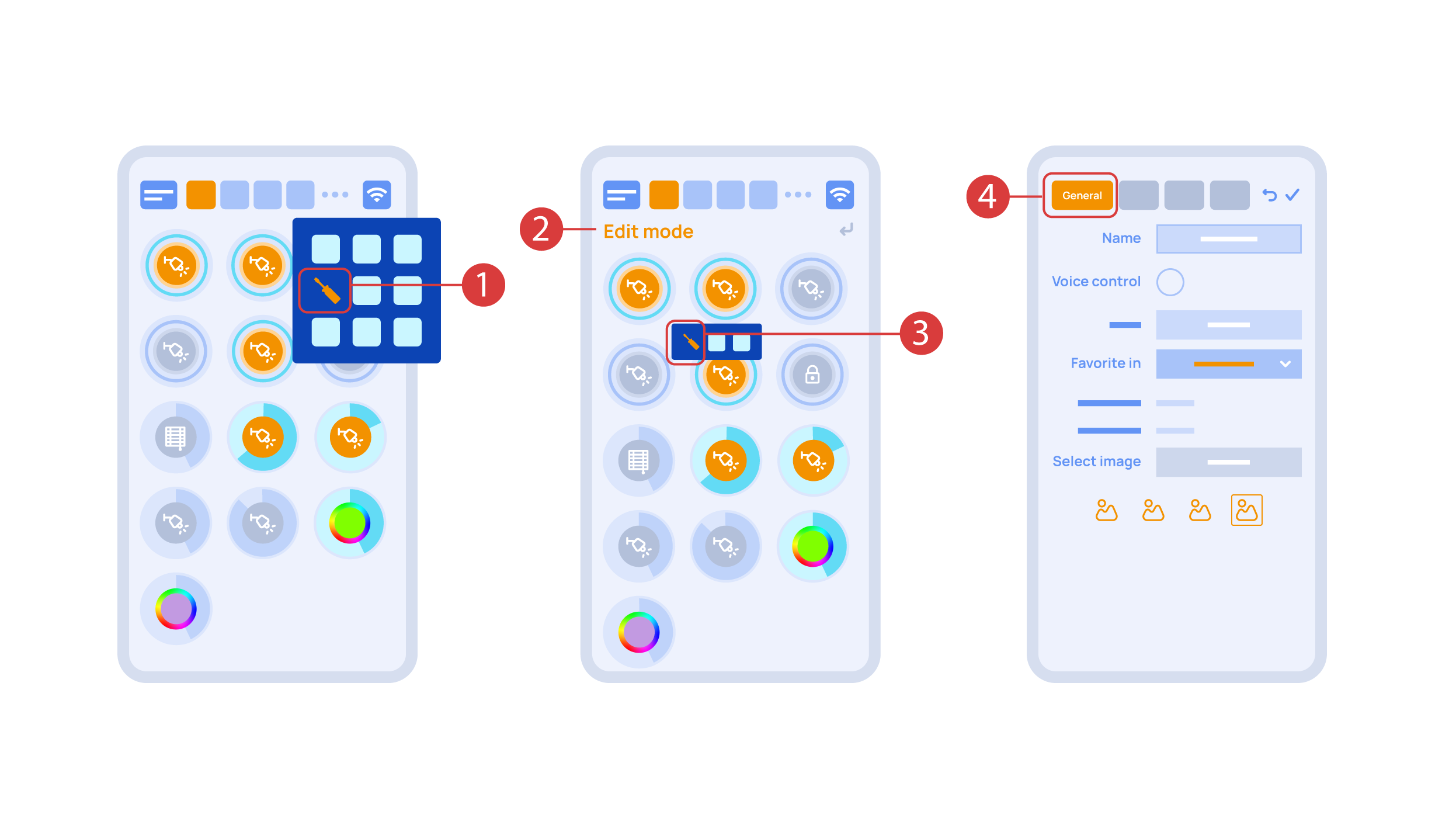
Now we can set up these executors. In order to do this, enter the additional menu ① and activate the edit mode, by pressing the appropriate icon .
Now we are in the edit mode ②, which can be seen from the appropriate notification in the top part of the screen. In this mode, when we press and hold an icon, we can move it among other elements and place it into another Room by placing it in the Area-choosing Menu and then choosing the area that we need. A long press ③ of the element starts the menu, from which we set up the current element.In the ‘General’ ④ section we can change the name of the element, add a voice command for it, change an icon or add the element to ‘Favorites’.
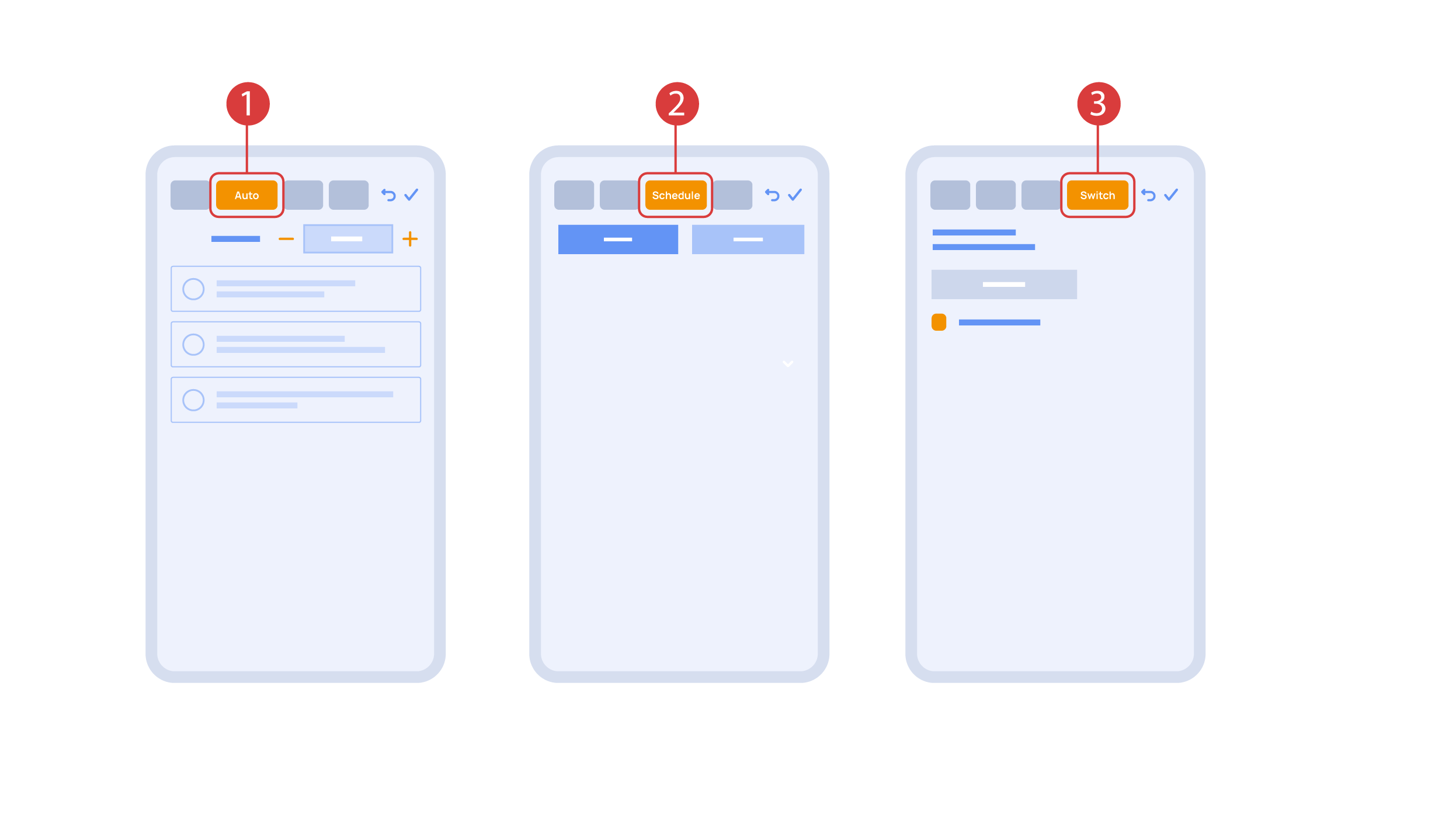
‘Auto’ section ① lets us activate the automation with a few clicks, as well as set up its parameters.
In the ‘schedule’ section ②, you can determine the schedule when the given element will turn on or off, including by using the time of the setting and rising of the sun.
The ‘Switches’ tab ③ lets you bind a button to control the executor.
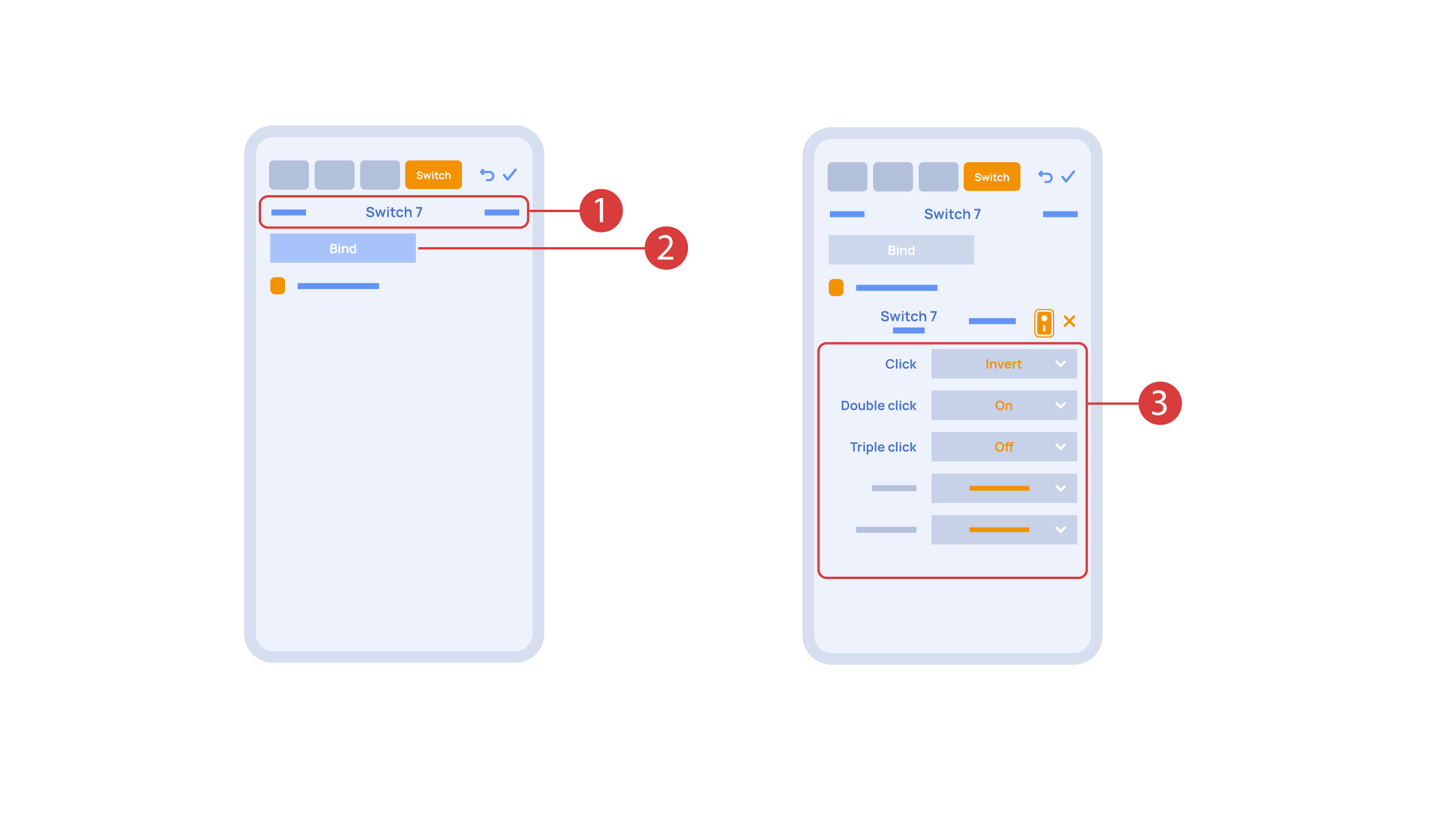
In order to do this, ① we press the button we need to bind. The system displays it, after which we press ‘Bind’② and save the changes. Now this button controls the executor
The ‘Switches’ tab ③ also features additional button setup options. For example, we can program the executor to be controlled with a double or triple click of a button, as well as define an action performed by this, for example ‘only turning on’ or ‘only turning off’ an executor. In this case we are setting up the button to do the following: one click will cause the lamp to toggle, a double click will turn it on and a triple click will turn it off. In this way a single button can perform up to five different actions.
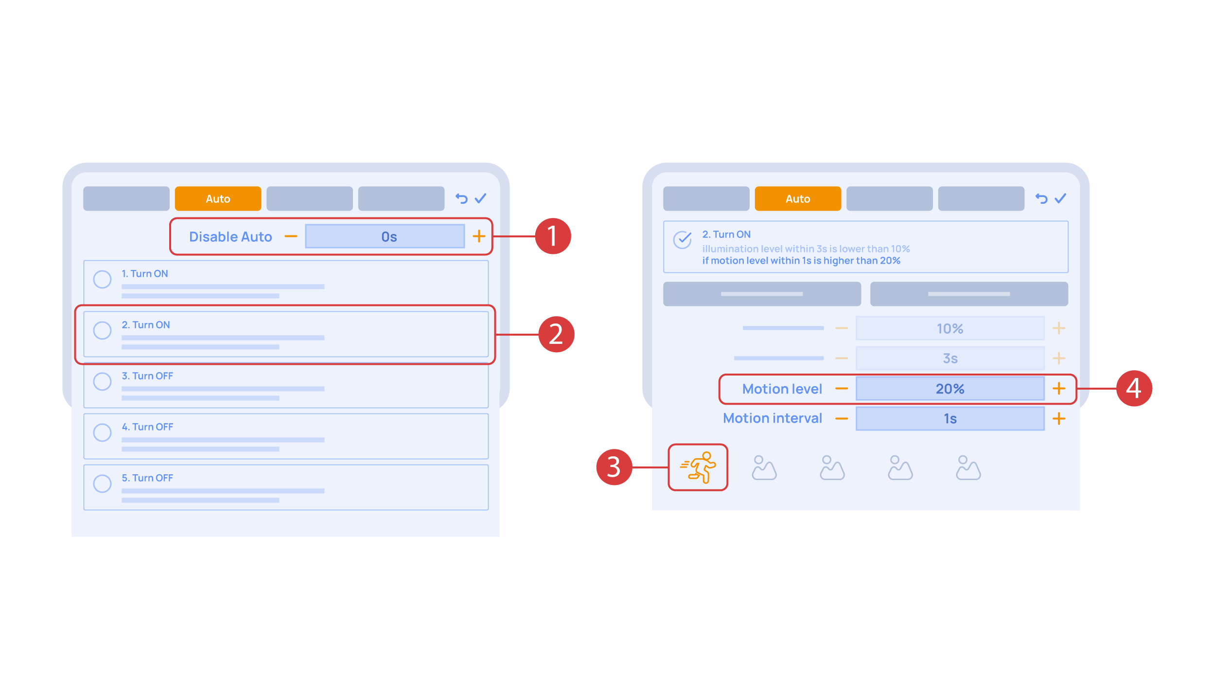
Let’s also set up basic automation of turning an executor on or off with the help of a motion sensor.
The ‘Auto period’ ① option sets the time for which the automation is disabled after an executor is manually controlled.For our demonstration purposes, we will set it to zero.
Then we will activate the automation ② to turn on the executor when motion is detected. We choose the motion sensor ③ and the level of motion ④. We can also choose a light sensor and its parameters.
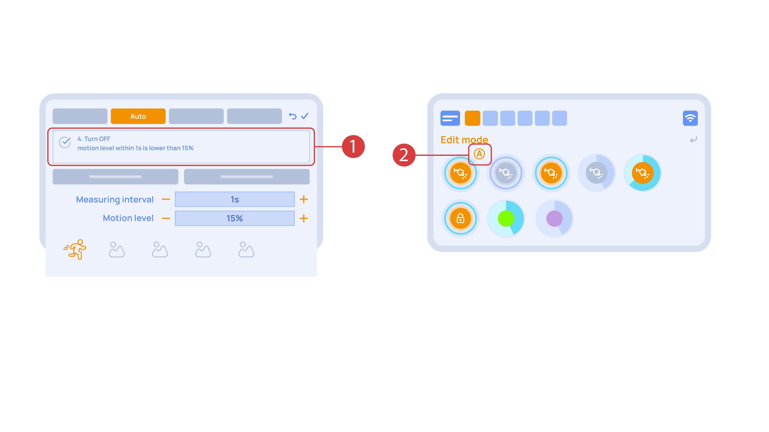
Now we will activate turning off ① of an executor if there is no motion: we choose the same sensor, set a lower threshold and a minimal time.Save the changes.
The extra ‘A’ icon ② will be added to the executor icon, meaning that automation has been set up for it. Now the lamp will be turned on when motion is detected and instantly turned off when no motion is detected.
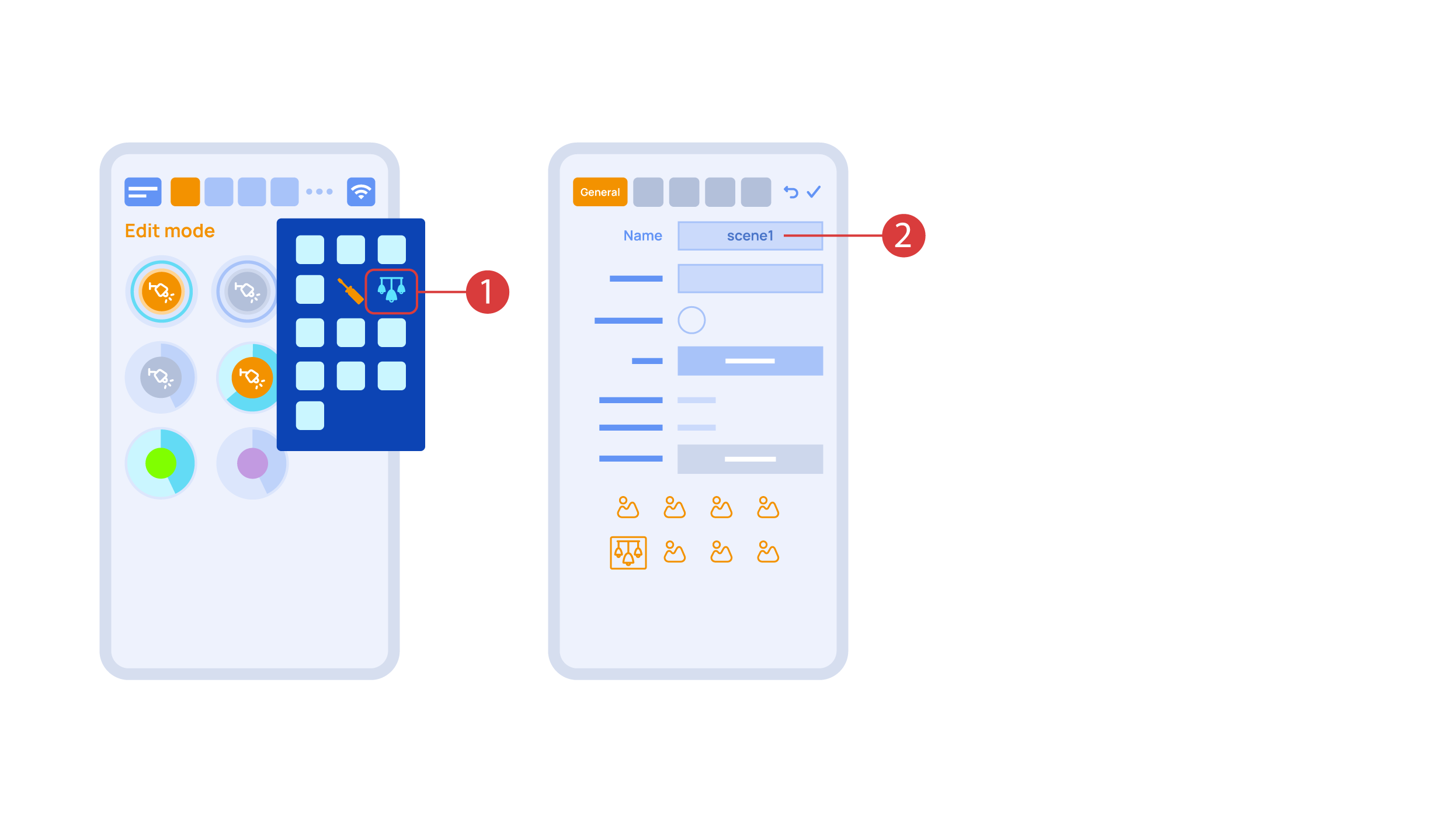
Let’s create a light scheme. For this we need to select the appropriate item in the additional menu ①. Give the light scheme a name ②.
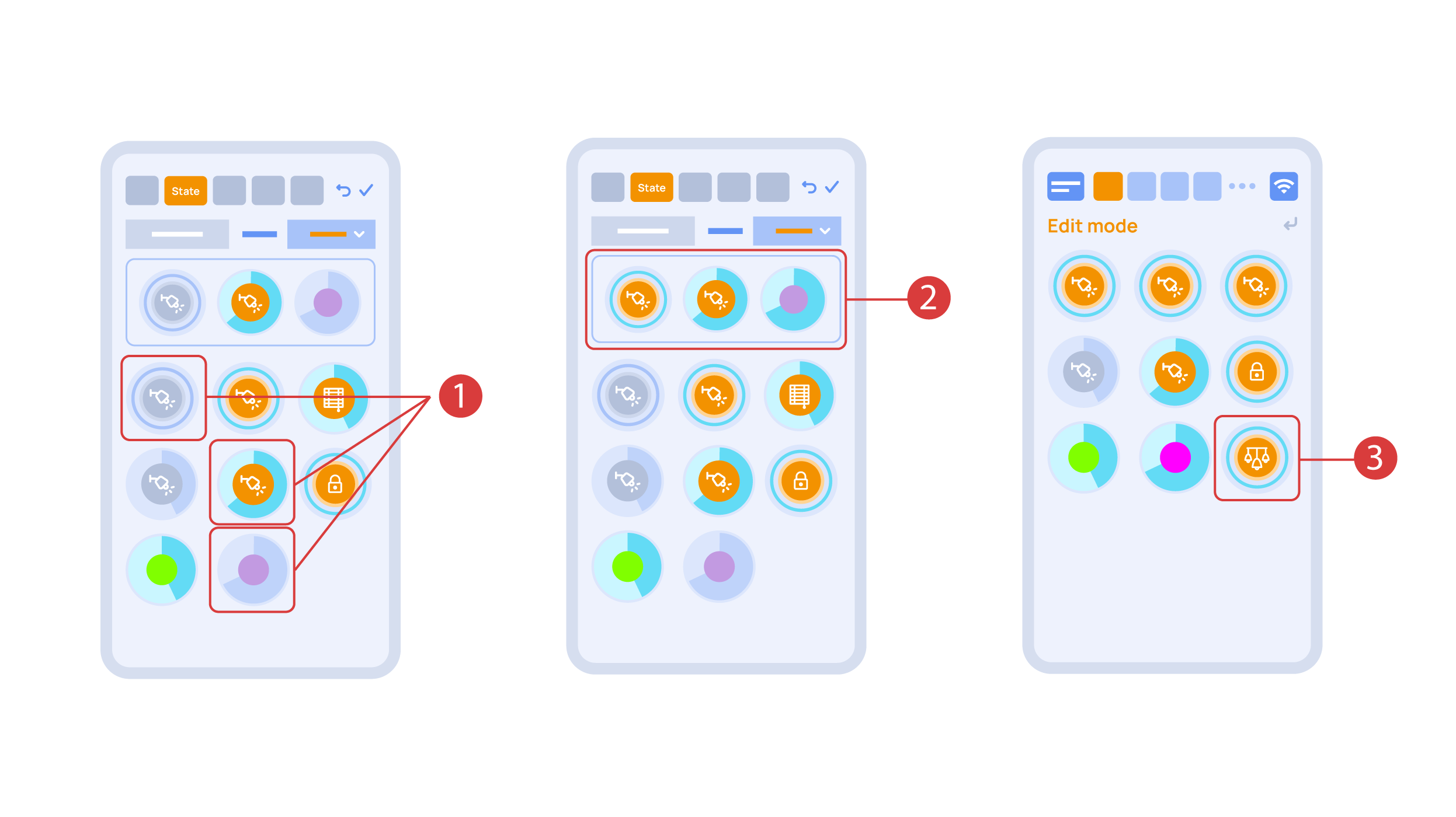
In the ‘State’ tab, use a long press to add the lights we want to use into the light scene ① and set up their state ②. ‘Auto’, ‘Schedule’, ‘Switch’ tabs are the same for all the executors.
Save the changes and we are able to use the newly-created light scheme ③ immediately.
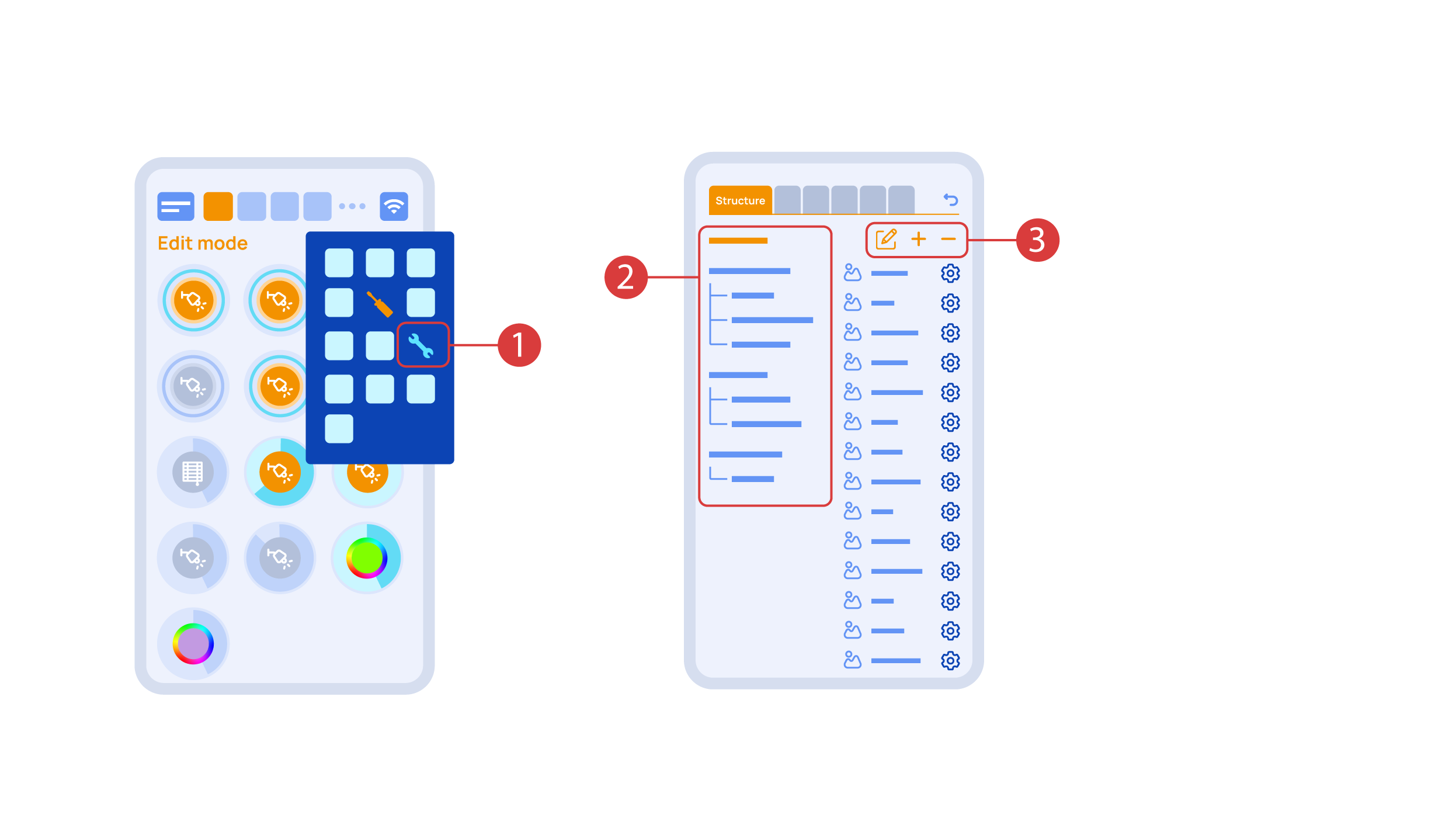
While you are in the Edit Mode, there is a ‘Setup’ ① icon in the additional menu.
Here in the ‘Structure’② tab we can see all the areas.
We can create new ones ④, rename them and move the elements around.
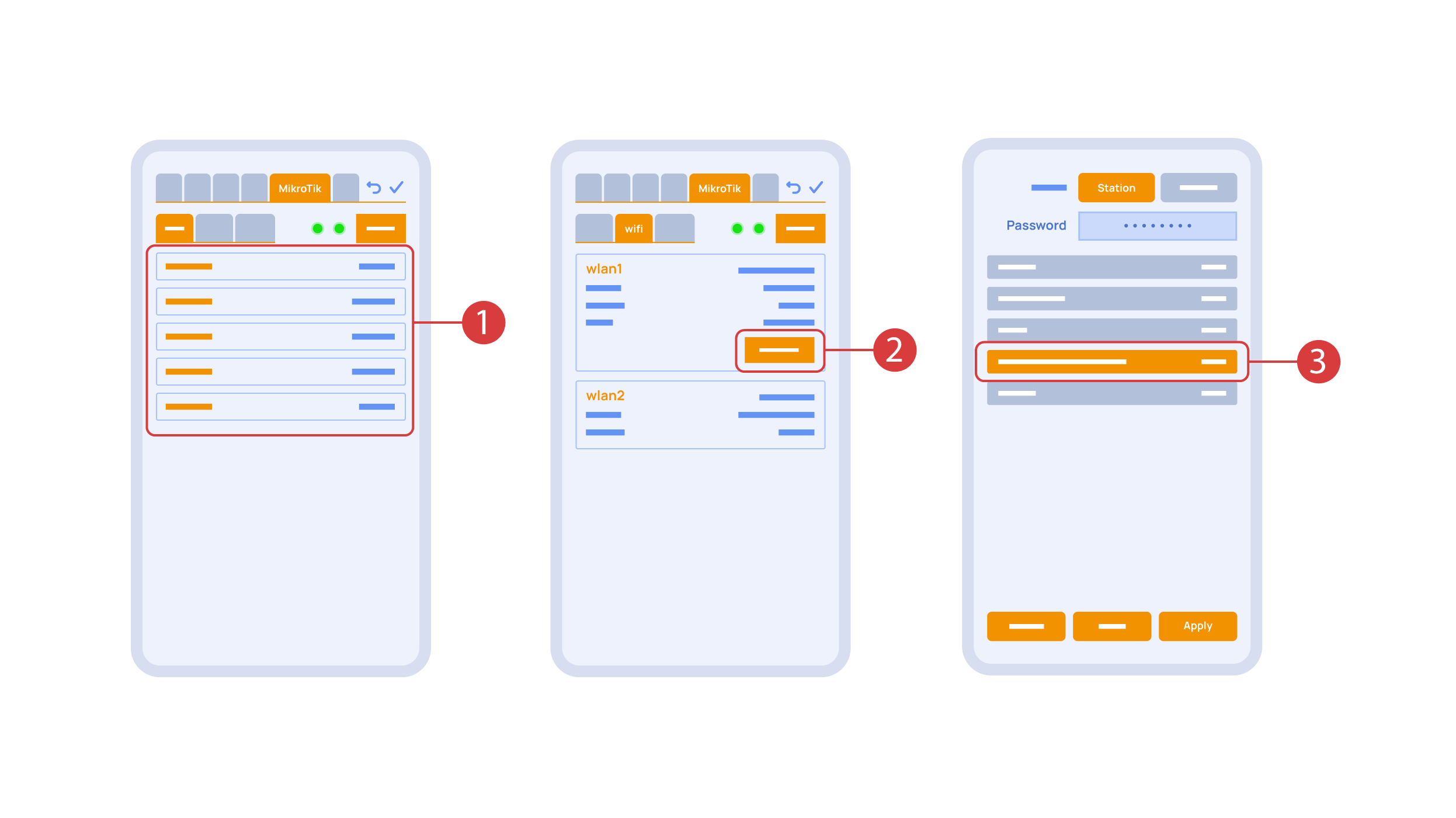
In the ‘Mikrotik’ tab ① you can see the current parameters of your router, which you can also connect to your local Wi-Fi network.
In order to do this, enter the Wi-Fi sub-menu, click the wlan1 interface configuration ②, after which choose the ‘station’ mode, choose a Wi-Fi network out of the list ③ of available ones and enter the connection password.
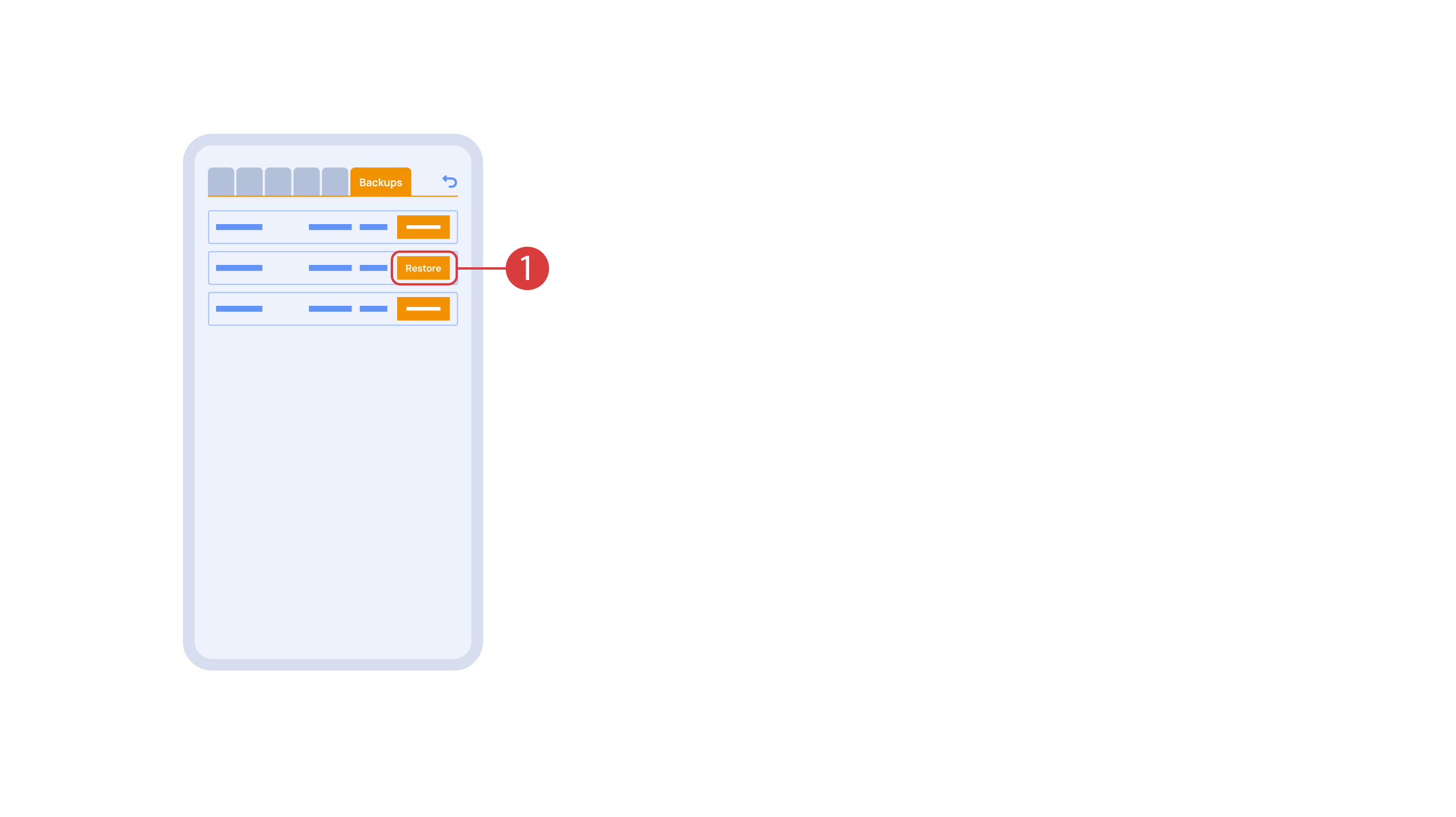
In the ‘Backups’ tab ① you can see the list of saved configurations, which can be restored if necessary.
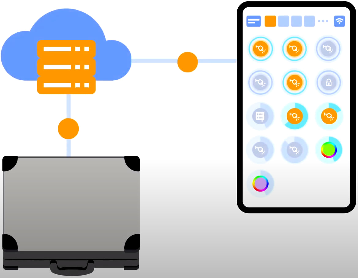
For cloud access to the device, you do not need any extra settings. The app detects the absence of the system in your local network and automatically establishes the connection via the cloud.
We thank you for watching this tutorial! If you have questions or need extra help, please do not hesitate to refer to our technical support team. See you in the next episodes!