Kurzanleitung
Schnelleinstieg/Unboxing.
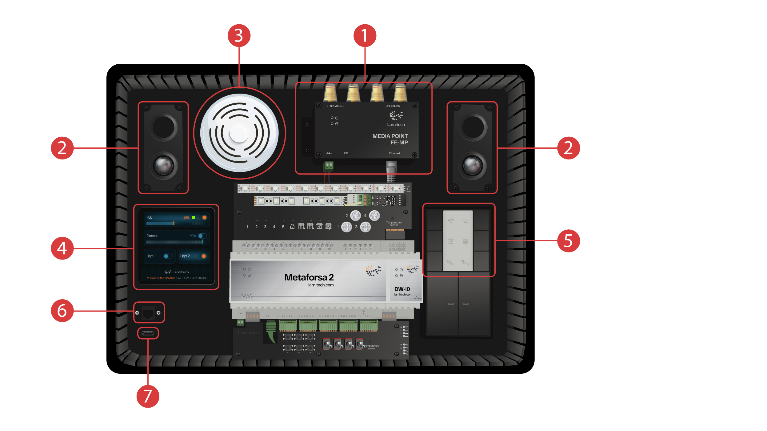
Herzlich willkommen bei unserem Channel! Dieses Video ist eine Anleitung, wie man das Larnitech-System schnell und mühelos einrichten kann. Die Einrichtung wird mit Hilfe eines Präsentationskoffers durchgeführt. Ein Trainingsset besteht aus einem Präsentationskoffer ① und einer Box mit verschiedenen weiteren Dingen ②.
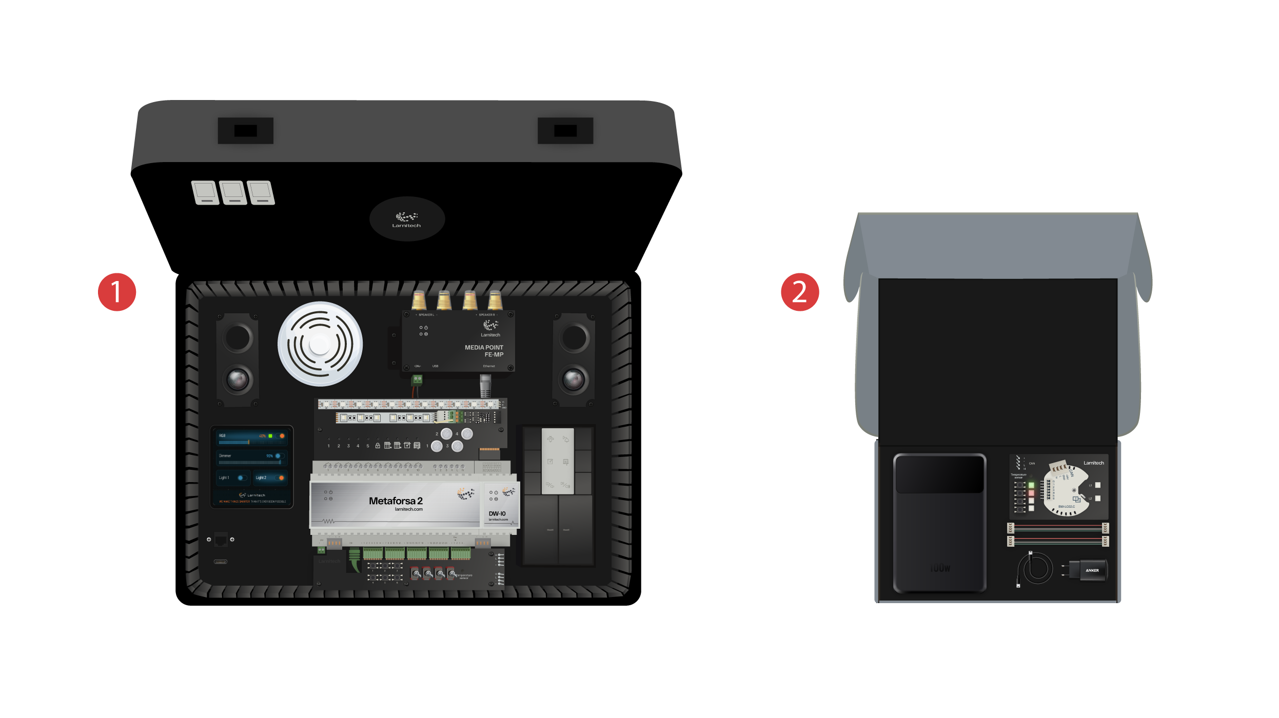
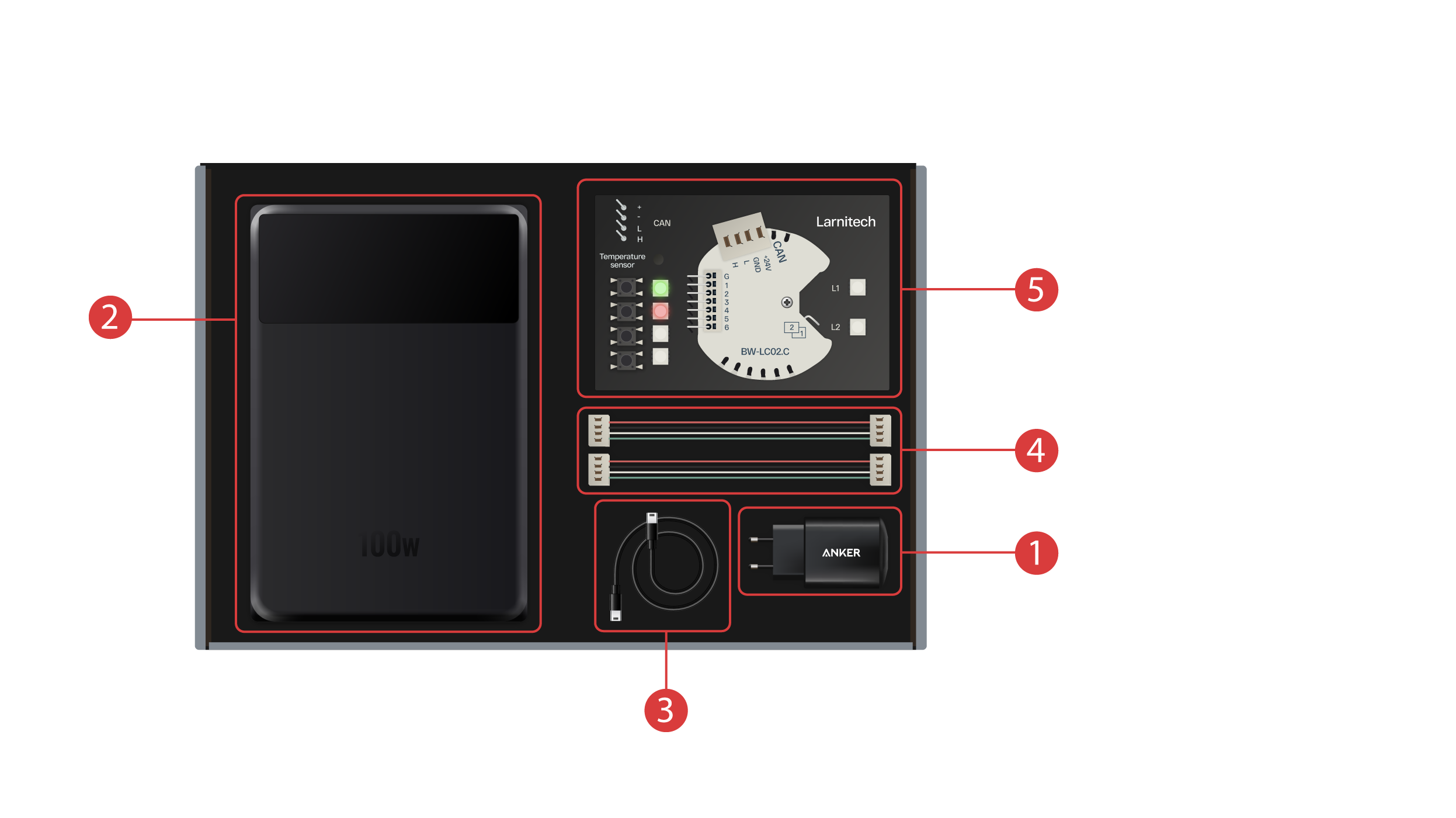
Die Box enthält folgendes:
① - Ein Netzteil mit Typ-C-USB-Anschluss, das die Power-Delivery-Technologie unterstützt;
② - Eine Powerbank mit Display und Typ-C-Ausgang zum Aufladen des Präsentationskoffers;
③ - Type-C cable with a power consumption indicator;
④ - 2 CAN-Bus-Kabel;
⑤ - emonstrationsplatine mit einem BW-LC02-Modul mit 2 LED-Leuchten, 4 Tasten mit Hintergrundbeleuchtung und einem daran angeschlossenen Temperatursensor.
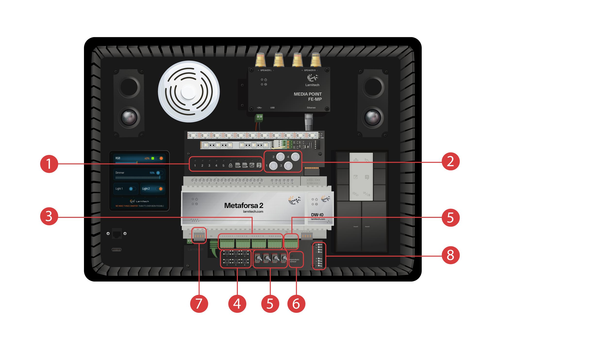
Der Präsentationskoffer enthält die folgenden Elemente: Ein ‘Metaforsa 2’-Modul.
Das ‘Metaforsa 2’ hat:
① - 10 Relaiskanäle mit LED-Leuchten für die Statusanzeige;
② - 4 dimmbare Kanäle mit dimmbaren LED-Leuchten;
③ - 24 Eingangskanäle mit 6 Tasten ④ und 4 Schaltern, ⑤ um verschiedene Sensoren zu simulieren.
⑥ - Eingangskanäle für Temperatursensoren und einem angeschlossenen Sensor.
⑦ - CAN-Bus für den Anschluss zusätzlicher Geräte. Daran sind weitere Module des Präsentationskoffers angeschlossen, sowie 2 Ports ⑧ für den Anschluss von externen Geräten;
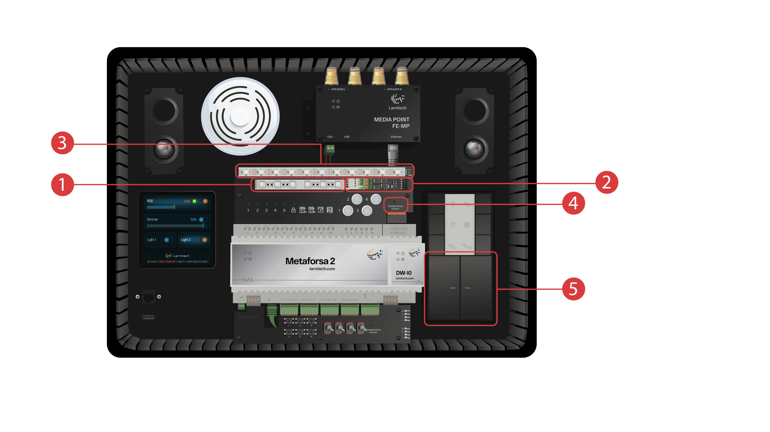
DW-IO-Modul
Dieses Modul hat 14 universelle Eingangs-/Ausgangskanäle, an die die folgenden Geräte angeschlossen sind:
① - 4-Kanal-RGBW-Leiste, angeschlossen über den Stromverstärker AMP5V-4 ② ;
③ - Eine Leiste mit angesteuerten LED-Leuchten. Jede dieser LED-Leuchten kann in ihrer eigenen Farbe leuchten.
④ - Temperatursensor;
⑤ - Und zwei Tasten mit Hintergrundbeleuchtung.
Der Präsentationskoffer enthält außerdem:
① - Einen Media Point FE-MP mit ② zwei Lautsprechern;
③ - Einen Sechs-in-Eins CW-CO2-Sensor, der folgendes misst: Bewegungsgrad, Beleuchtung, Temperatur, Luftfeuchte, CO2-Gehalt und er besitzt außerdem einen Infrarot-Transmitter;
④ - ein 4-Zoll-Sensor-Panel LCP4, das entweder eine normale oder eine für Wandpanels angepasste Schnittstelle anzeigen kann.
Im Koffer befindet sich ein Tastenkontrollmodul BW-SW24, an das eine 6-Tasten 24-Volt JUNG-Tastatur ⑤ angeschlossen ist.
Und ein WLAN-Router, der entweder über einen Ethernet-Anschluss ⑥ an der Vorderseite des Koffers oder über ein verfügbares WLAN-Netzwerk mit dem Internet verbunden werden kann.
Für die Stromversorgung steht ein Typ-C-Anschluss zur Verfügung ⑦, der sich am Frontpanel befindet.
Alle im Präsentationskoffer installierten Geräte werden mit einer Spannung von 20 Volt betrieben, was für den Benutzer absolut sicher ist.
Schließen Sie das Stromkabel und das Ethernet-Kabel an. Wenn Sie keine Möglichkeit haben, eine Verbindung über das Ethernet herzustellen, zeigen wir Ihnen später in diesem Video, wie Sie sich mit dem eingebauten Router mit Ihrem WLAN-Netzwerk verbinden.
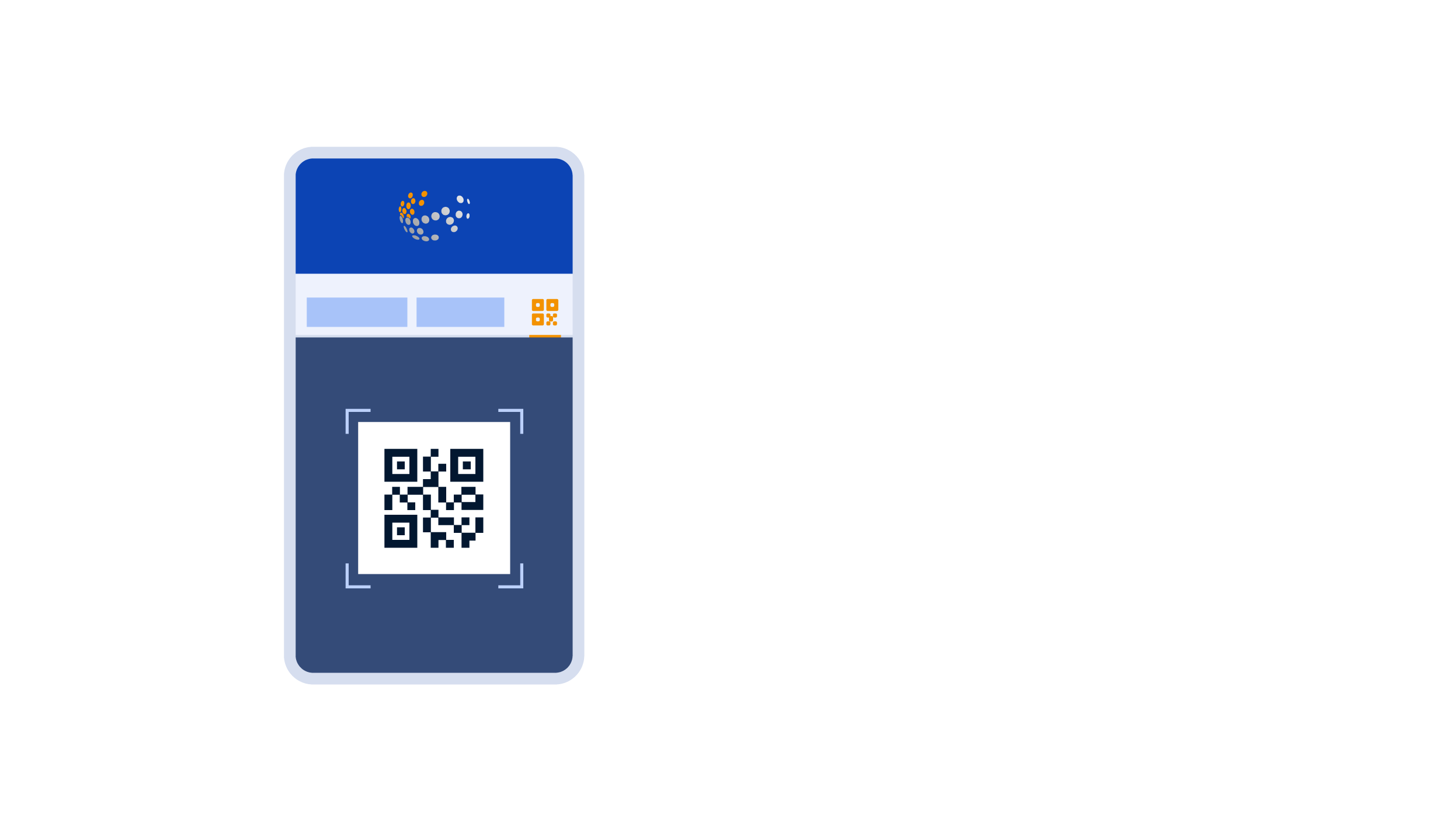
Um fortzufahren muss die Larnitech-App auf Ihrem Smartphone oder Tablet installiert sein. Scannen Sie einfach den ersten QR-Code auf dem Deckel Ihres Koffers.
Wenn nach der Installation und dem Aufruf der App die Verbindung nicht automatisch hergestellt wird, müssen Sie sich mithilfe Ihres Mobilgerätes mit dem WLAN-Netzwerk „Larnitech_case_5G“ verbinden. Starten Sie dann die App und scannen Sie den ersten QR-Code im Bereich „Verbindungen“.
Falls das Präsentationsgerät nicht mit dem Internet verbunden ist, müssen Sie ggf. die Datenübertragung auf Ihrem Mobilgerät deaktivieren.
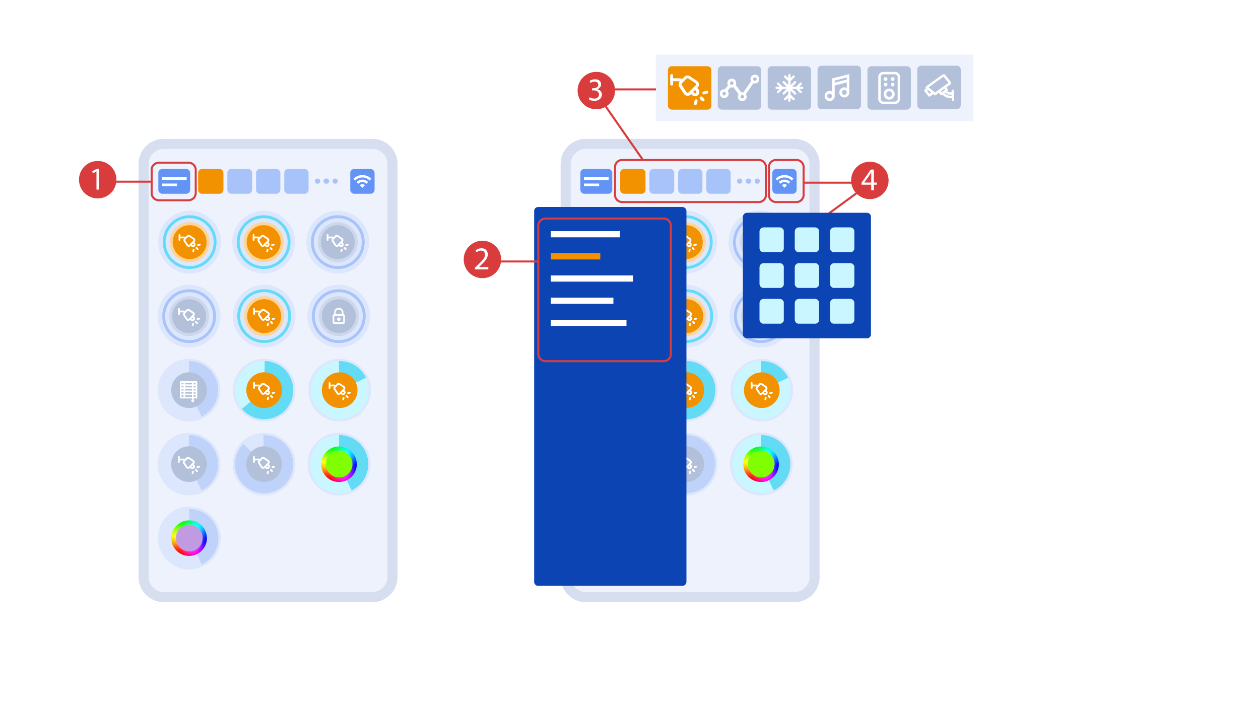
The main screen of the app has several key elements. In the upper left corner there is the ‘area select’ menu ①.
Just click one of the available areas in order to manage it ②.
Then there are icons which let you choose the executors, sensors, climate, multimedia, remote controls and cameras ③. In the right corner there is an icon for the additional menu ④. Inside the icon you can also see the status of the current connection.
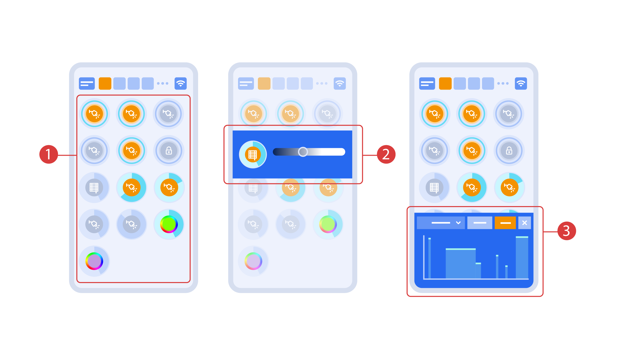
Turning the executors ① on or off is done with a simple click. In order to change the level of lighting ②, color of lights or the position of the blinds, use a double click. In order to access the status history ③ of this executor or sensor, press and hold the icon for one second.
A short press of the physical buttons on the panel turns the light on or off. Press and hold the button to change the light brightness.
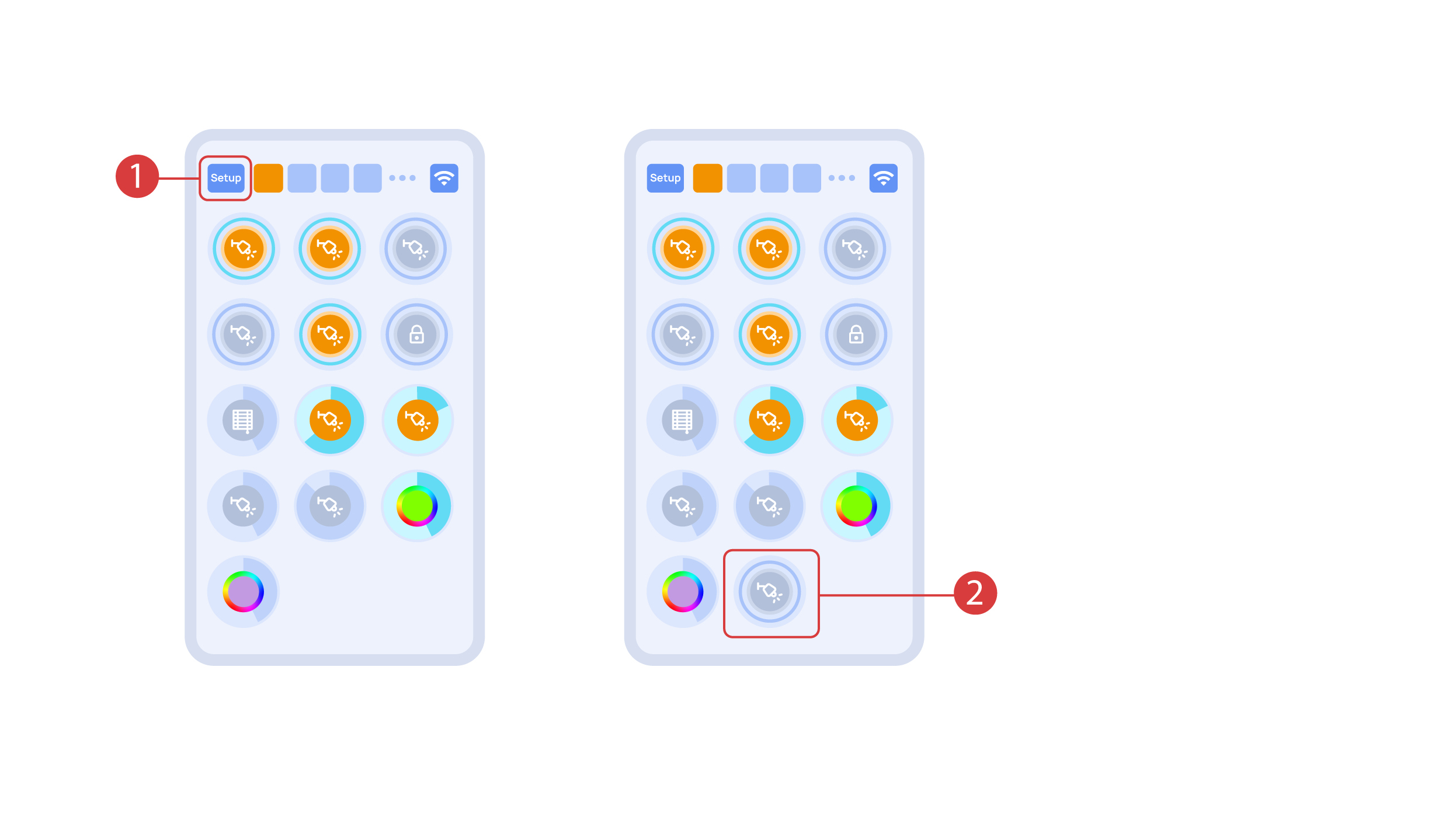
In order to demonstrate the Plug and Play function, we open the executors in the Setup area ① and connect the module to the CAN bus. The system automatically detects the new module and adds it to the ‘Setup’ area, ② where we are able to control the new module instantly.
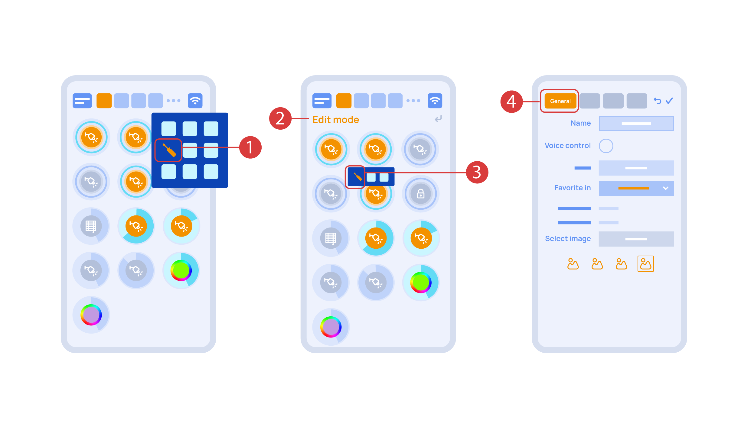
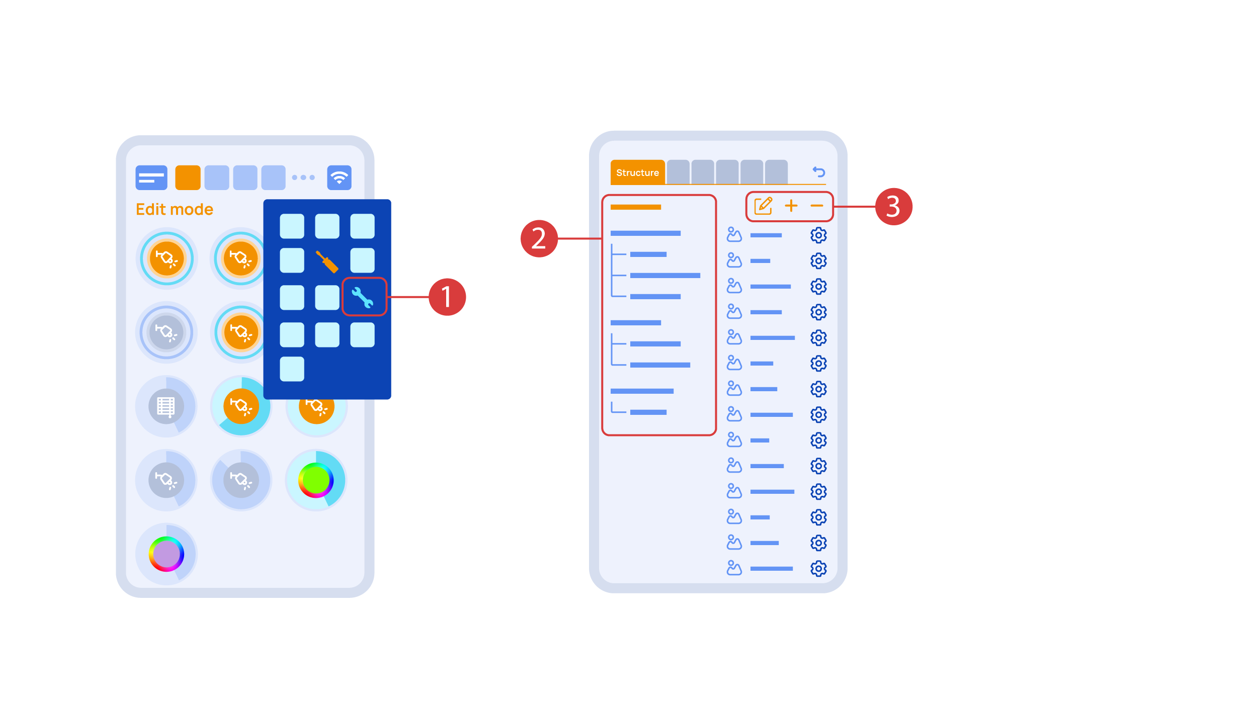
Now we can set up these executors. In order to do this, enter the additional menu ① and activate the edit mode, by pressing the appropriate icon .
Now we are in the edit mode ②, which can be seen from the appropriate notification in the top part of the screen. In this mode, when we press and hold an icon, we can move it among other elements and place it into another Room by placing it in the Area-choosing Menu and then choosing the area that we need. A long press ③ of the element starts the menu, from which we set up the current element.In the ‘General’ ④ section we can change the name of the element, add a voice command for it, change an icon or add the element to ‘Favorites’.
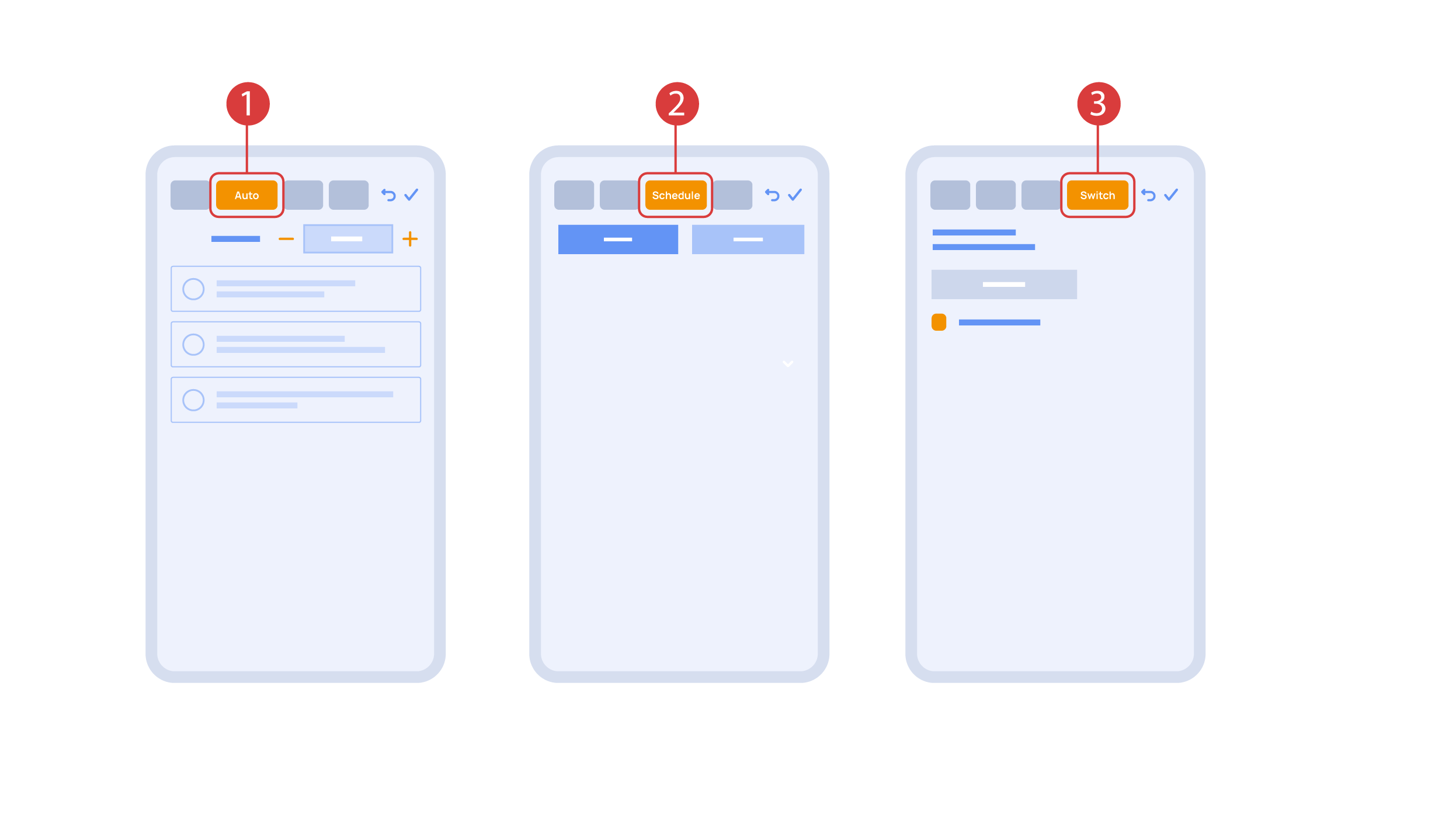
‘Auto’ section ① lets us activate the automation with a few clicks, as well as set up its parameters.
In the ‘schedule’ section ②, you can determine the schedule when the given element will turn on or off, including by using the time of the setting and rising of the sun.
The ‘Switches’ tab ③ lets you bind a button to control the executor.
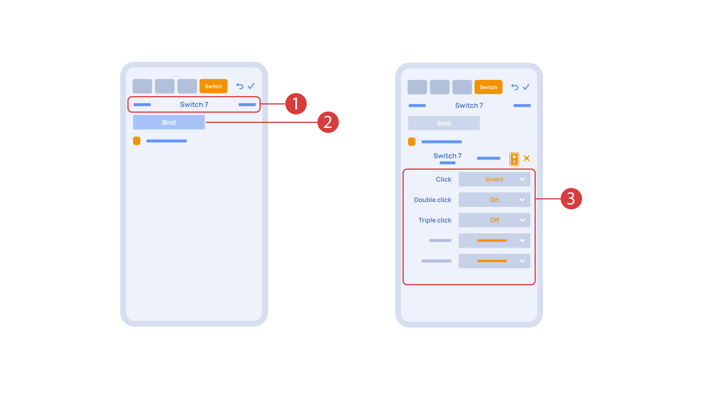
In order to do this, ① we press the button we need to bind. The system displays it, after which we press ‘Bind’② and save the changes. Now this button controls the executor
The ‘Switches’ tab ③ also features additional button setup options. For example, we can program the executor to be controlled with a double or triple click of a button, as well as define an action performed by this, for example ‘only turning on’ or ‘only turning off’ an executor. In this case we are setting up the button to do the following: one click will cause the lamp to toggle, a double click will turn it on and a triple click will turn it off. In this way a single button can perform up to five different actions.
Let’s also set up basic automation of turning an executor on or off with the help of a motion sensor.
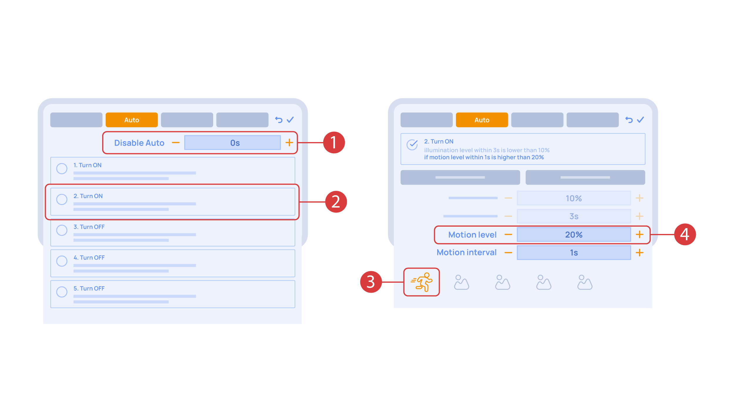
The ‘Auto period’ ① option sets the time for which the automation is disabled after an executor is manually controlled.For our demonstration purposes, we will set it to zero.
Then we will activate the automation ② to turn on the executor when motion is detected. We choose the motion sensor ③ and the level of motion ④. We can also choose a light sensor and its parameters.
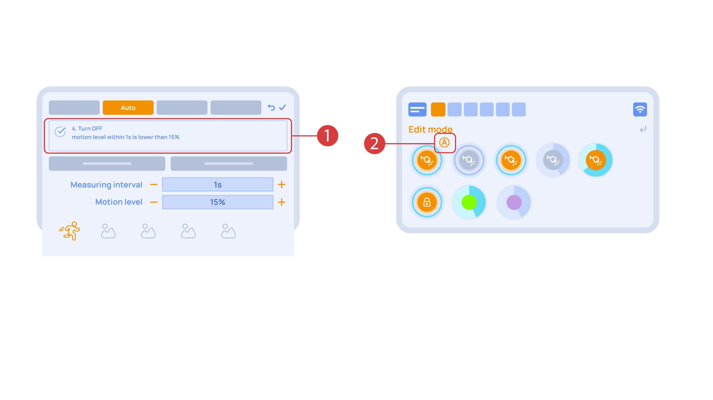
Now we will activate turning off ① of an executor if there is no motion: we choose the same sensor, set a lower threshold and a minimal time.Save the changes.
The extra ‘A’ icon ② will be added to the executor icon, meaning that automation has been set up for it. Now the lamp will be turned on when motion is detected and instantly turned off when no motion is detected.
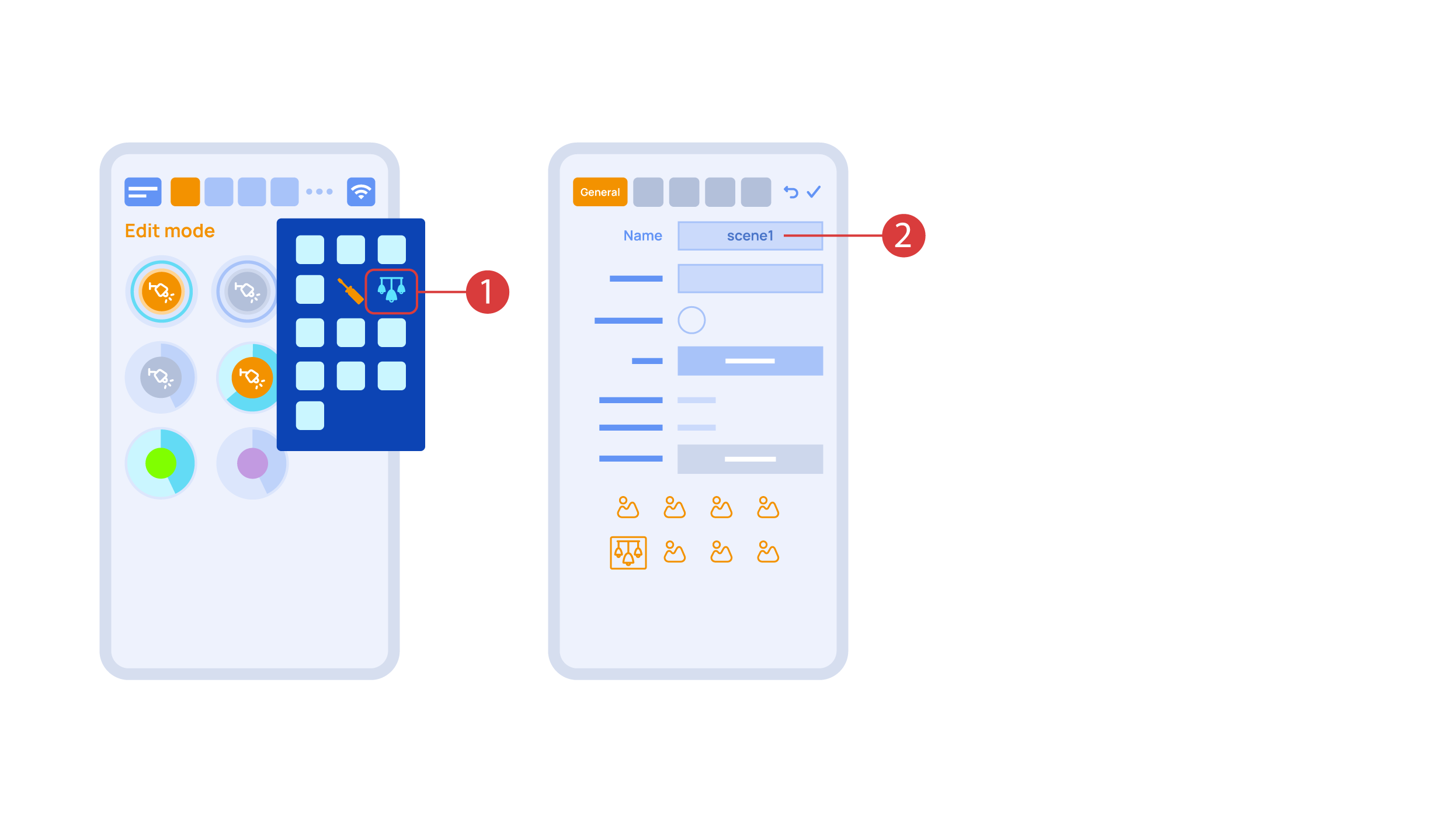
Let’s create a light scheme. For this we need to select the appropriate item in the additional menu ①. Give the light scheme a name ②.
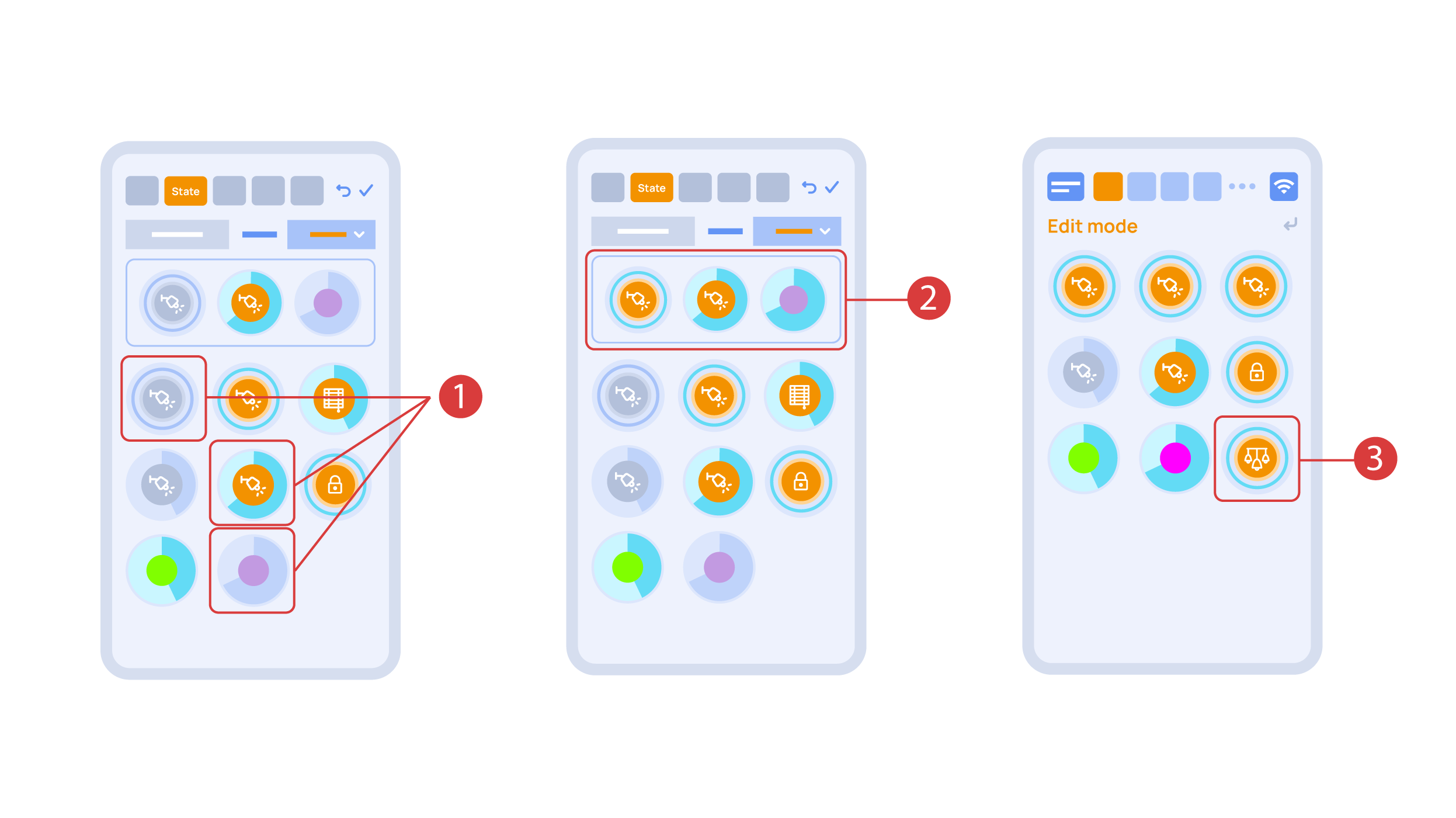
In the ‘State’ tab, use a long press to add the lights we want to use into the light scene ① and set up their state ②. ‘Auto’, ‘Schedule’, ‘Switch’ tabs are the same for all the executors.
Save the changes and we are able to use the newly-created light scheme ③ immediately.
While you are in the Edit Mode, there is a ‘Setup’ ① icon in the additional menu.
Here in the ‘Structure’② tab we can see all the areas.
We can create new ones ④, rename them and move the elements around.
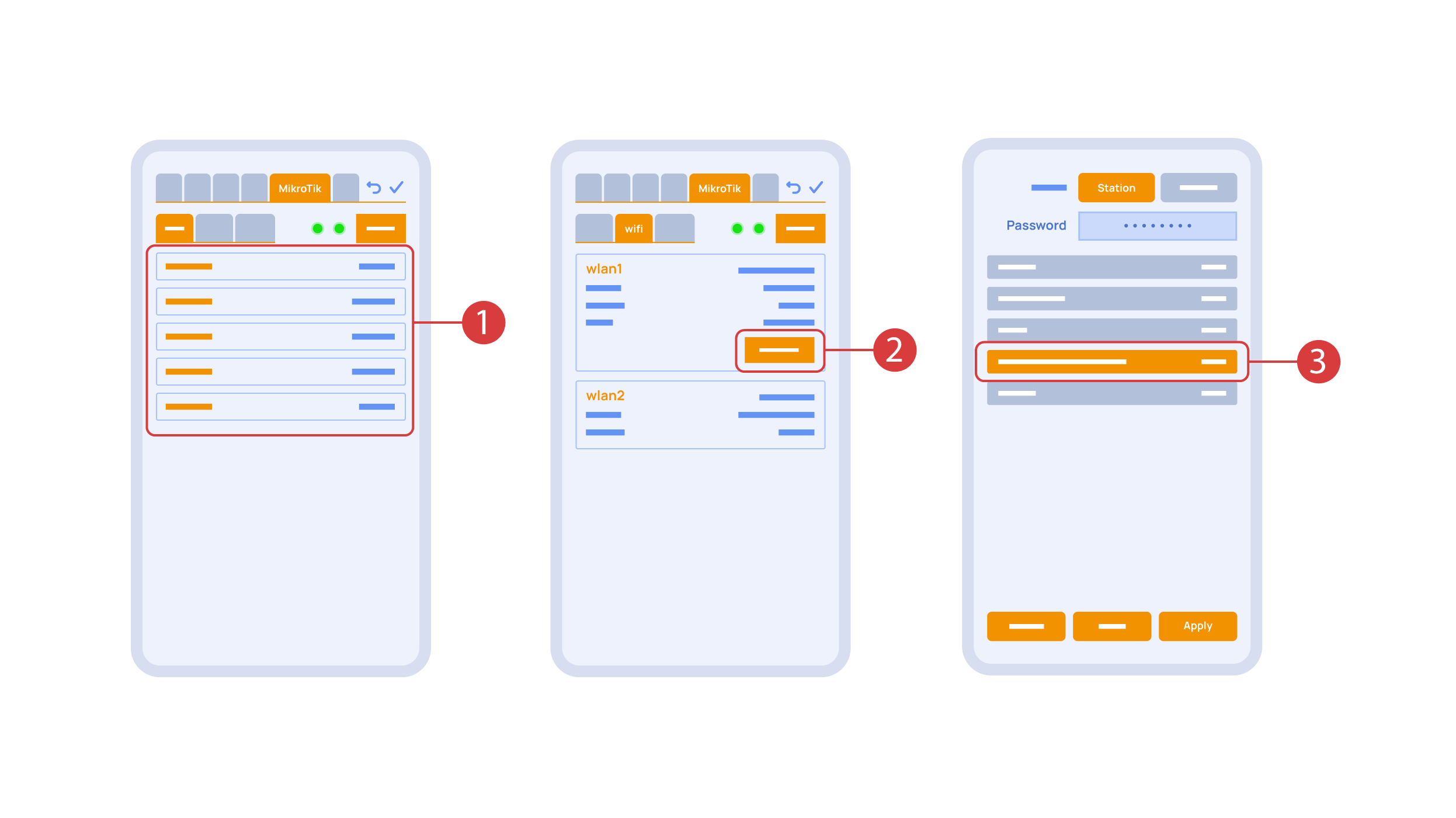
In the ‘Mikrotik’ tab ① you can see the current parameters of your router, which you can also connect to your local Wi-Fi network.
In order to do this, enter the Wi-Fi sub-menu, click the wlan1 interface configuration ②, after which choose the ‘station’ mode, choose a Wi-Fi network out of the list ③ of available ones and enter the connection password.
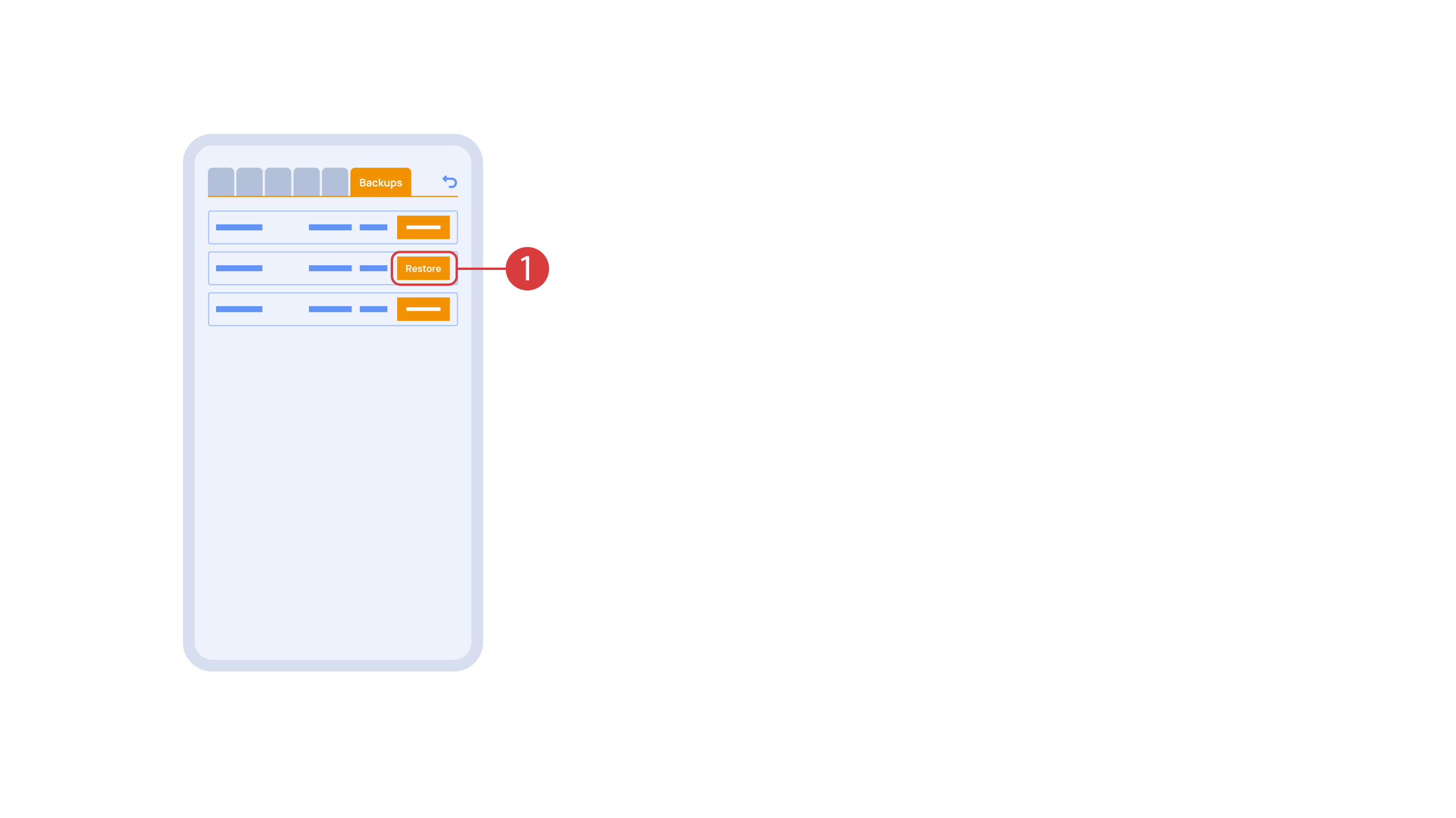
In the ‘Backups’ tab ① you can see the list of saved configurations, which can be restored if necessary.
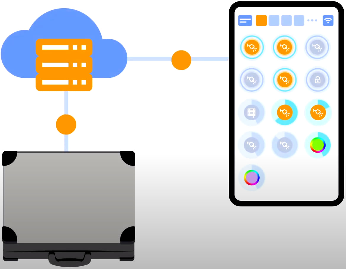
For cloud access to the device, you do not need any extra settings. The app detects the absence of the system in your local network and automatically establishes the connection via the cloud.
We thank you for watching this tutorial! If you have questions or need extra help, please do not hesitate to refer to our technical support team. See you in the next episodes!