Difference between revisions of "Quick Start Guide"
| Line 2: | Line 2: | ||
<translate> | <translate> | ||
<!--T:1--> | <!--T:1--> | ||
| − | <youtube width=" | + | <youtube width="800px">DIMELmedOHw</youtube> |
</translate> | </translate> | ||
<hr> | <hr> | ||
Revision as of 07:21, 29 September 2023
Quick start/unboxing.
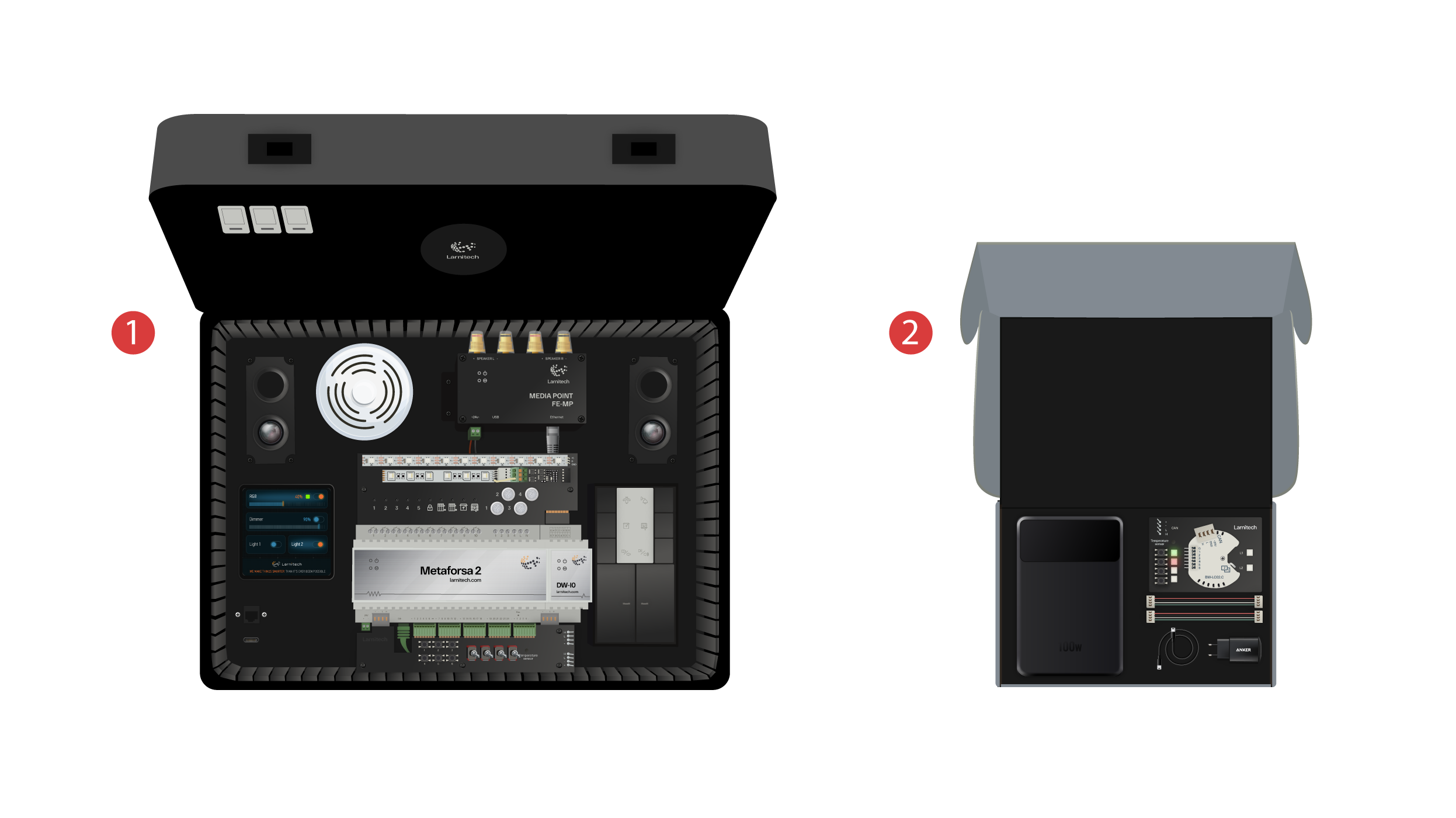
We welcome everyone at our channel! This video is a guide on how to set up the Larnitech system quickly and effortlessly. The setup is going to be done with the help of a demonstration case. A training set includes a demonstration suitcase ① and a box with several extra items ②.
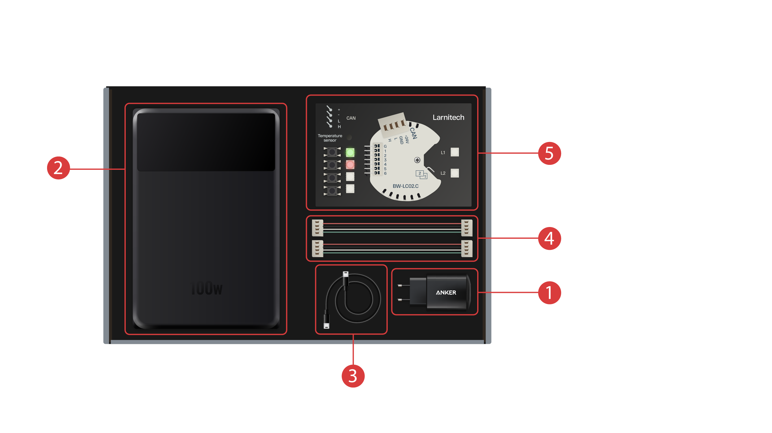
The box features the following:
① - A power unit with Type-C USB port, supporting the Power Delivery technology;
② - A power bank with a display and Type-C output port, which can be used to power up the demonstration suitcase;
③ - Type-C cable with a power consumption indicator;
④ - 2 CAN bus cables;
⑤ - Demonstration board featuring a BW-LC02 module with 2 LED lights, 4 buttons with backlight and a temperature sensor connected to it.
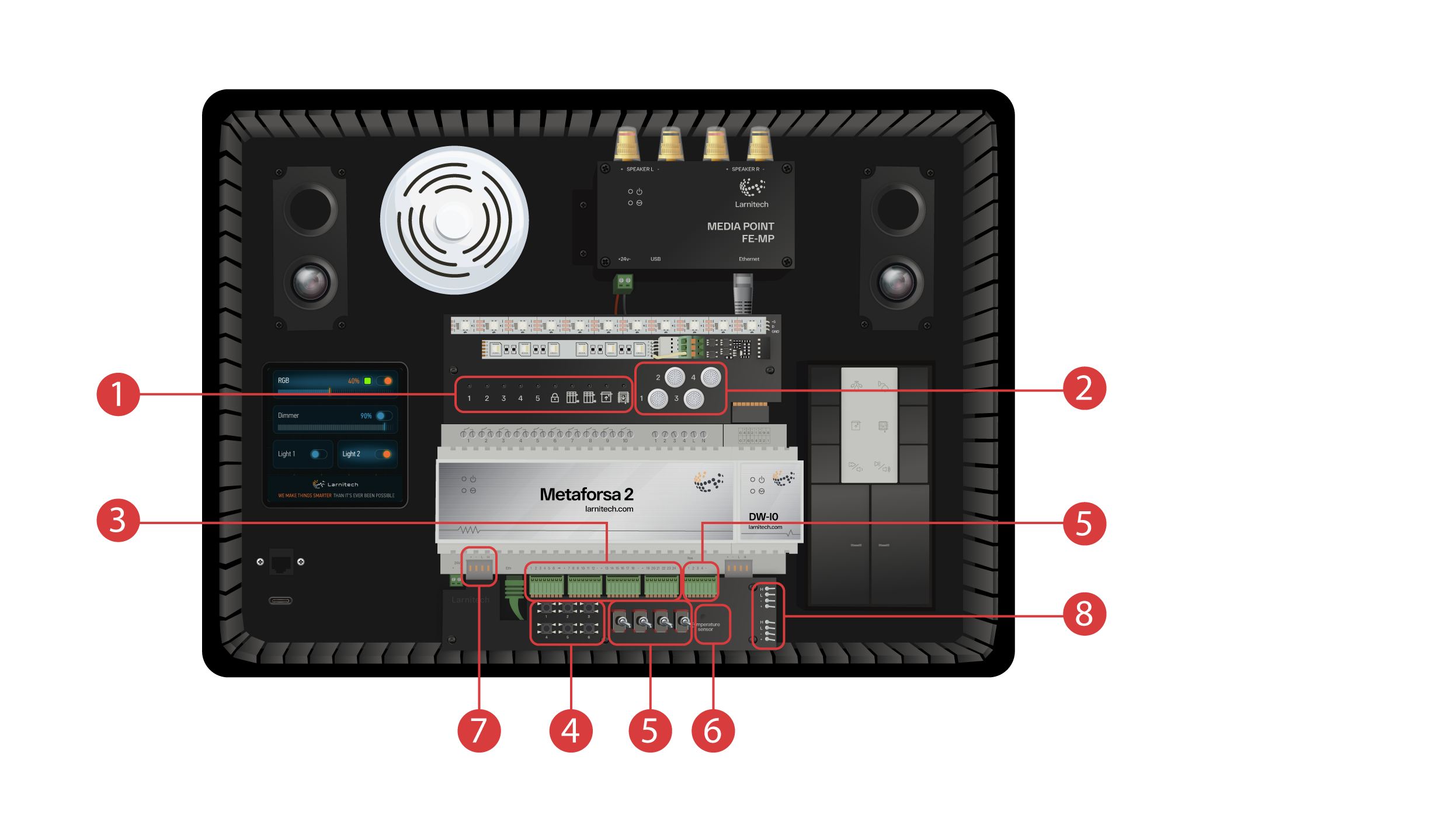
The demonstration suitcase contains the following elements: ‘Metaforsa 2’ module.
‘Metaforsa 2’ has:
① - 10 relay channels with LED lights connected to them, indicating their current status;
② - 4 dimmable channels, with dimmable LED lights connected to them;
③ - 24 input channels, with 6 buttons ④ and 4 switches ⑤ connected to them in order to imitate various sensors.
⑥ - Input channels for temperature sensors with one sensor connected to it.
⑦ - CAN bus for connecting extra devices. Other modules of the demonstration case are connected to it, as well as 2 ports ⑧ for connecting external devices;
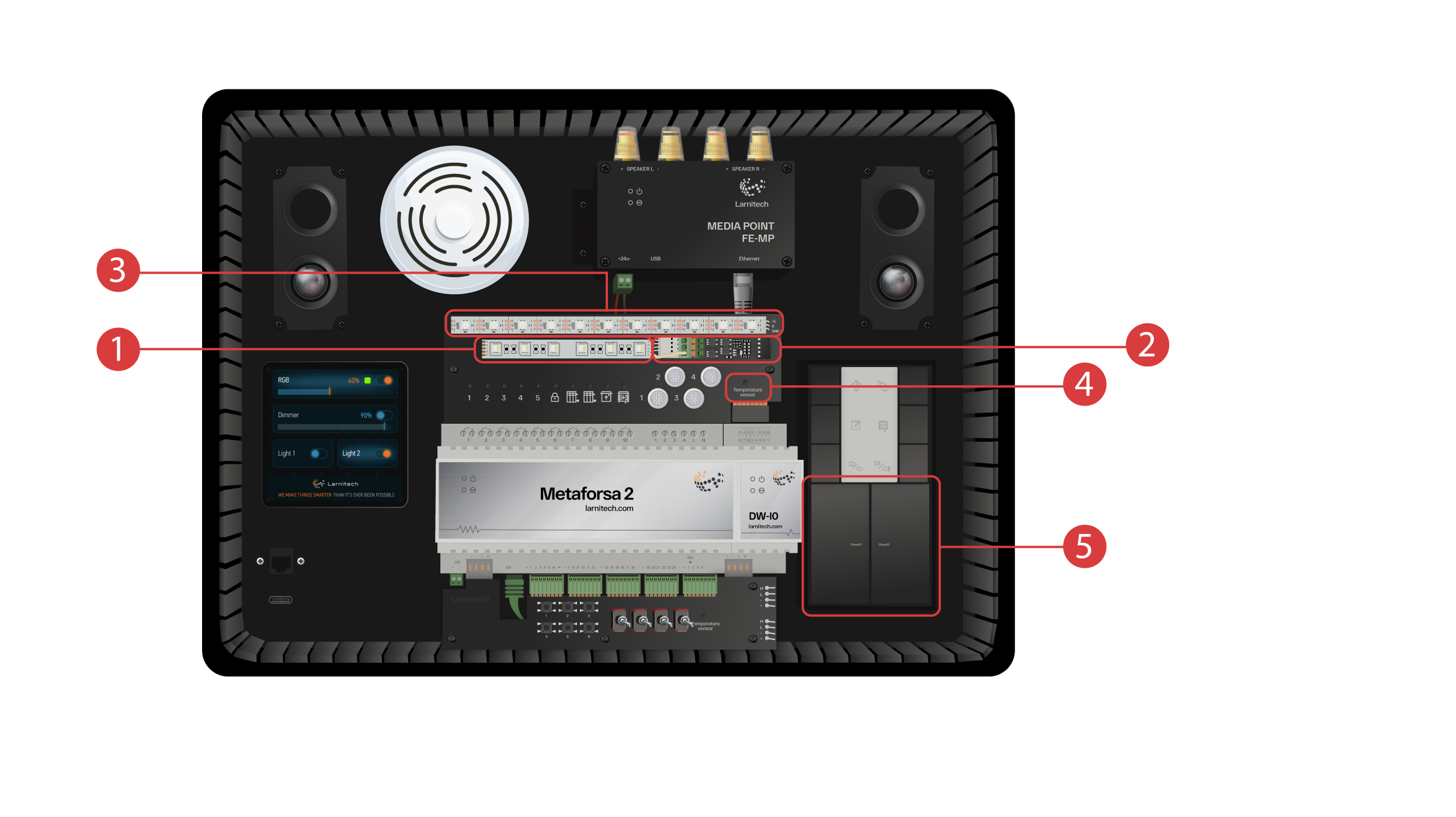
DW-IO module
This module has 14 universal input/output channels, with the following items connected to them:
① - 4-channel RGBW strip, connected via the AMP5V-4 ② current amplifier;
③ - A strip with addressed LED lights. Each of these LED lights can shine with its own individual color.
④ - Temperature sensor;
⑤ - And two buttons with backlight.
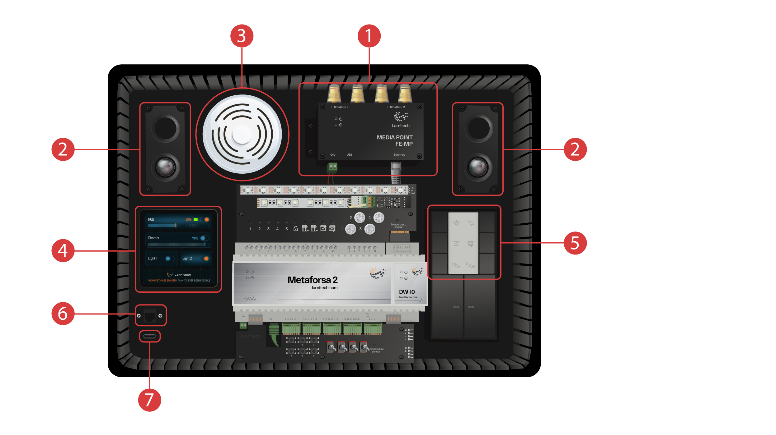
The demonstration case also features the following:
① - a Media Point FE-MP with ② two speakers;
③ - A six-in-one CW-CO2 sensor, which measures: Level of motion, Lighting, Temperature, Humidity, Level of CO2 and which has an infrared transmitter.
④ - a 4-inch sensor panel LCP4 which can display either a regular interface or an interface adapted for wall panels;
Inside the case there is a button control module BW-SW24 which has a six-button 24-volt JUNG keypad ⑤ connected to it.
And a Wi-Fi router, which can get connected to the internet either via an ethernet port ⑥ on the front panel of the case or via an available Wi-Fi network.
For power supply, there is a Type-C port ⑦, which is located on the front panel
All the equipment installed in the demonstration suitcase is powered by 20 Volts, which is absolutely safe for the user.
Connect the power cable and the Ethernet cable. If you do not have the possibility to connect via Ethernet, later in this video we will demonstrate how to connect the inbuilt router to your Wi-Fi network.
In order to proceed, the Larnitech app needs to be installed onto your smartphone or tablet. Just scan the first QR code from the top of your suitcase.
If after installing and starting the application the connection does not get established automatically, you will need to connect to Wi-Fi network ‘Larnitech_case_5G’ with the help of your mobile device. Then start the application and scan the first QR code in the ‘Connections’ section
You may need to turn off data transmission on your mobile device if the demonstration set is not connected to the Internet.

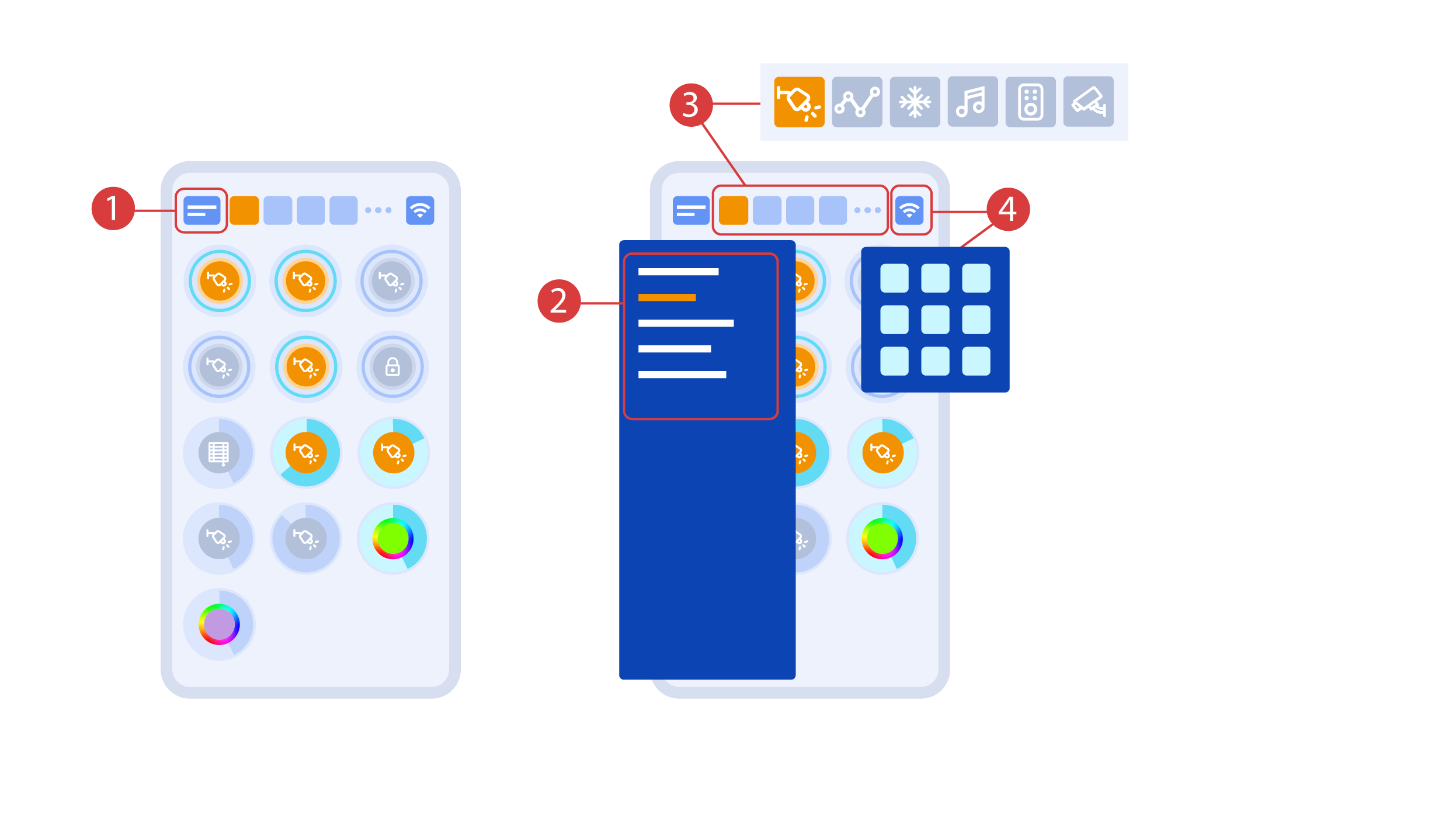
The main screen of the app has several key elements. In the upper left corner there is the ‘area select’ menu①.
Just click one of the available areas in order to manage it ②.
Then there are icons which let you choose the executors, sensors, climate, multimedia, remote controls and cameras ③. In the right corner there is an icon for the additional menu ④. Inside the icon you can also see the status of the current connection.
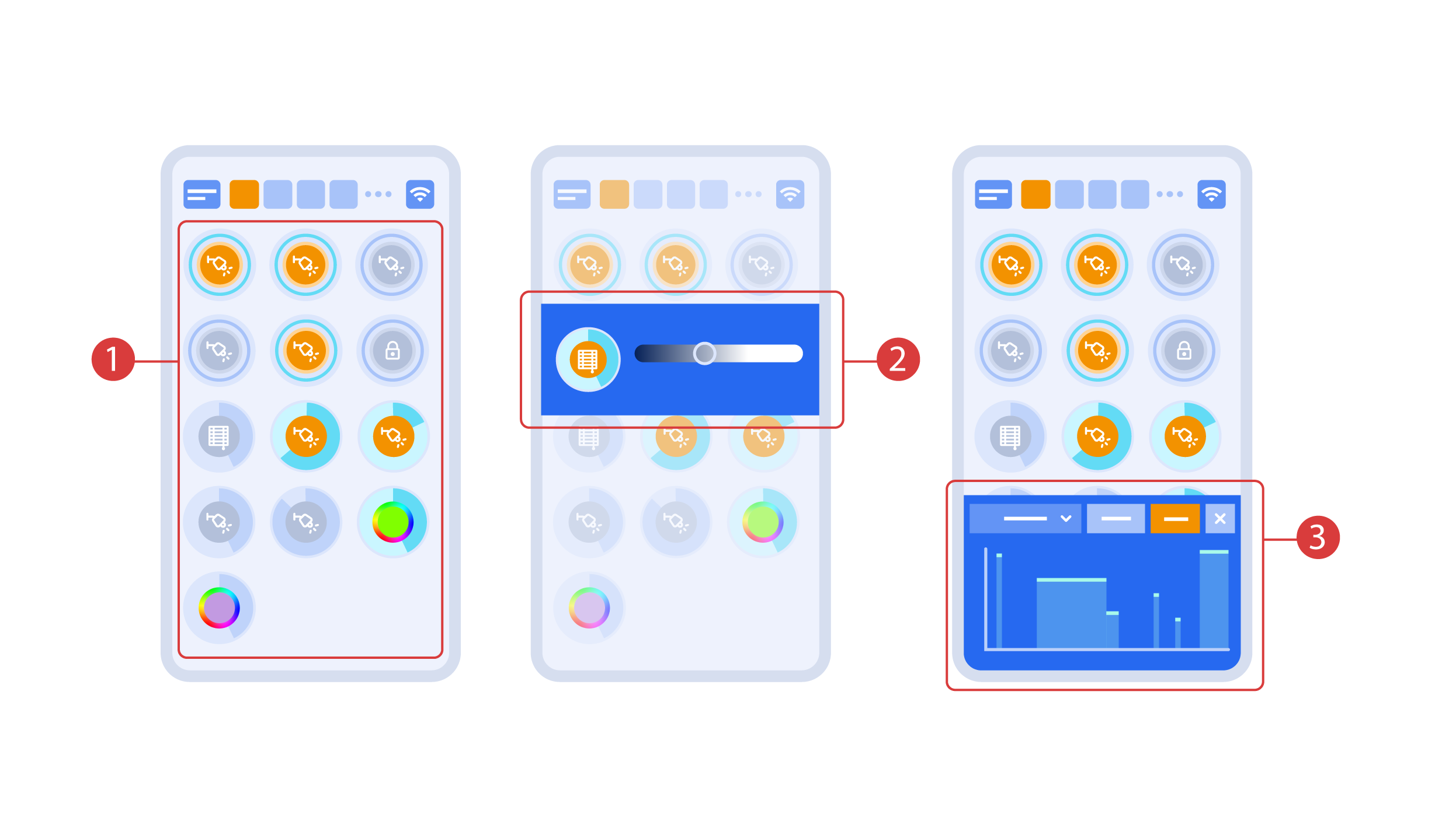
Turning the executors ① on or off is done with a simple click. In order to change the level of lighting ②, color of lights or the position of the blinds, use a double click. In order to access the status history ③ of this executor or sensor, press and hold the icon for one second.
A short press of the physical buttons on the panel turns the light on or off. Press and hold the button to change the light brightness.
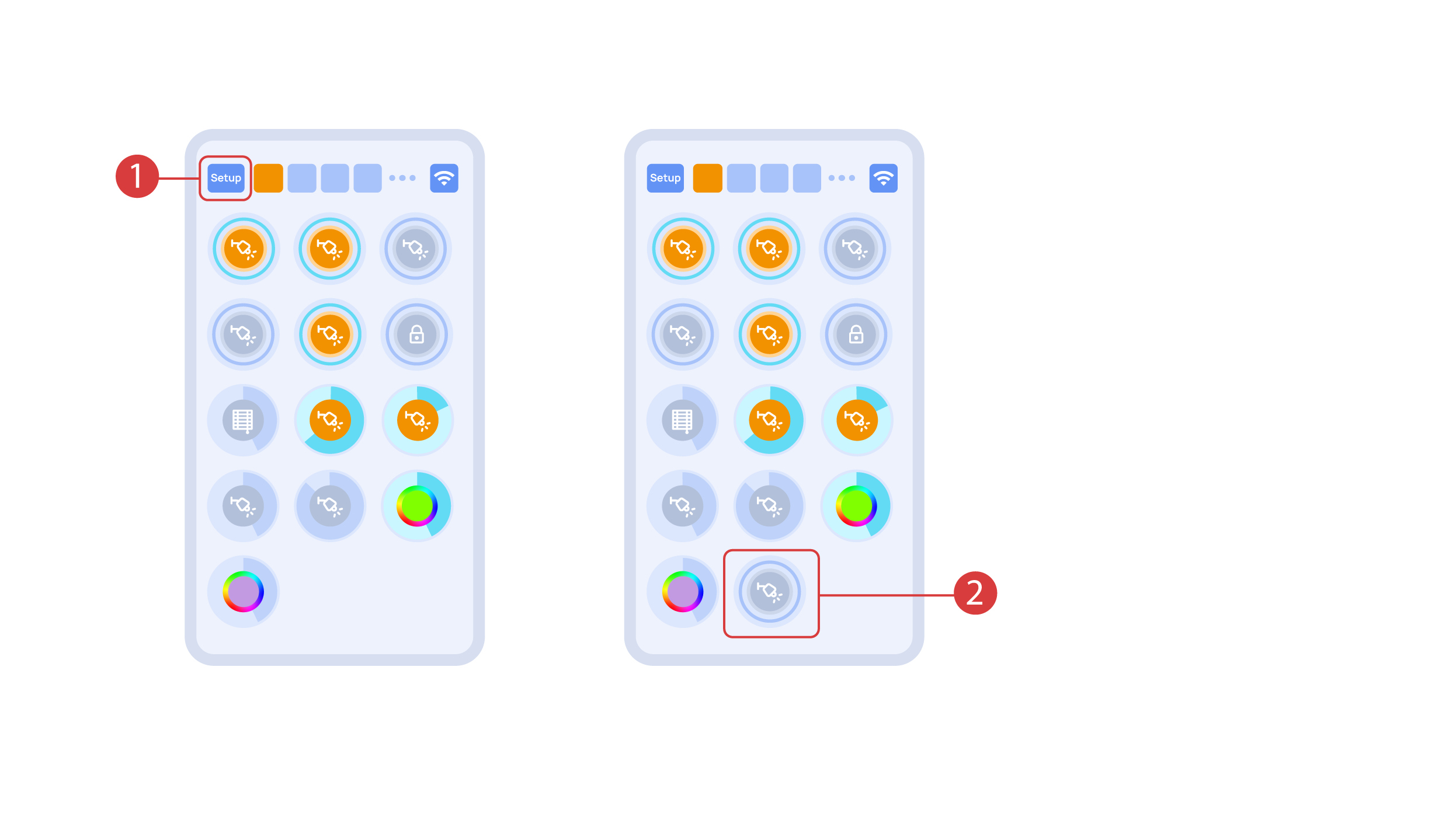
In order to demonstrate the Plug and Play function, we open the executors in the Setup area ① and connect the module to the CAN bus. The system automatically detects the new module and adds it to the ‘Setup’ area, ② where we are able to control the new module instantly.
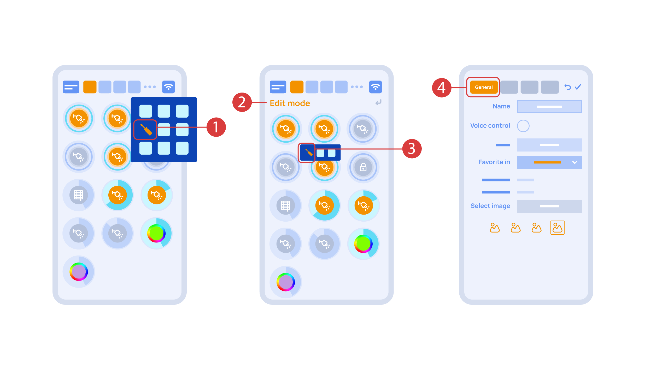
Now we can set up these executors. In order to do this, enter the additional menu ① and activate the edit mode, by pressing the appropriate icon .
Now we are in the edit mode ②, which can be seen from the appropriate notification in the top part of the screen. In this mode, when we press and hold an icon, we can move it among other elements and place it into another Room by placing it in the Area-choosing Menu and then choosing the area that we need. A long press ③ of the element starts the menu, from which we set up the current element.In the ‘General’ ④ section we can change the name of the element, add a voice command for it, change an icon or add the element to ‘Favorites’.
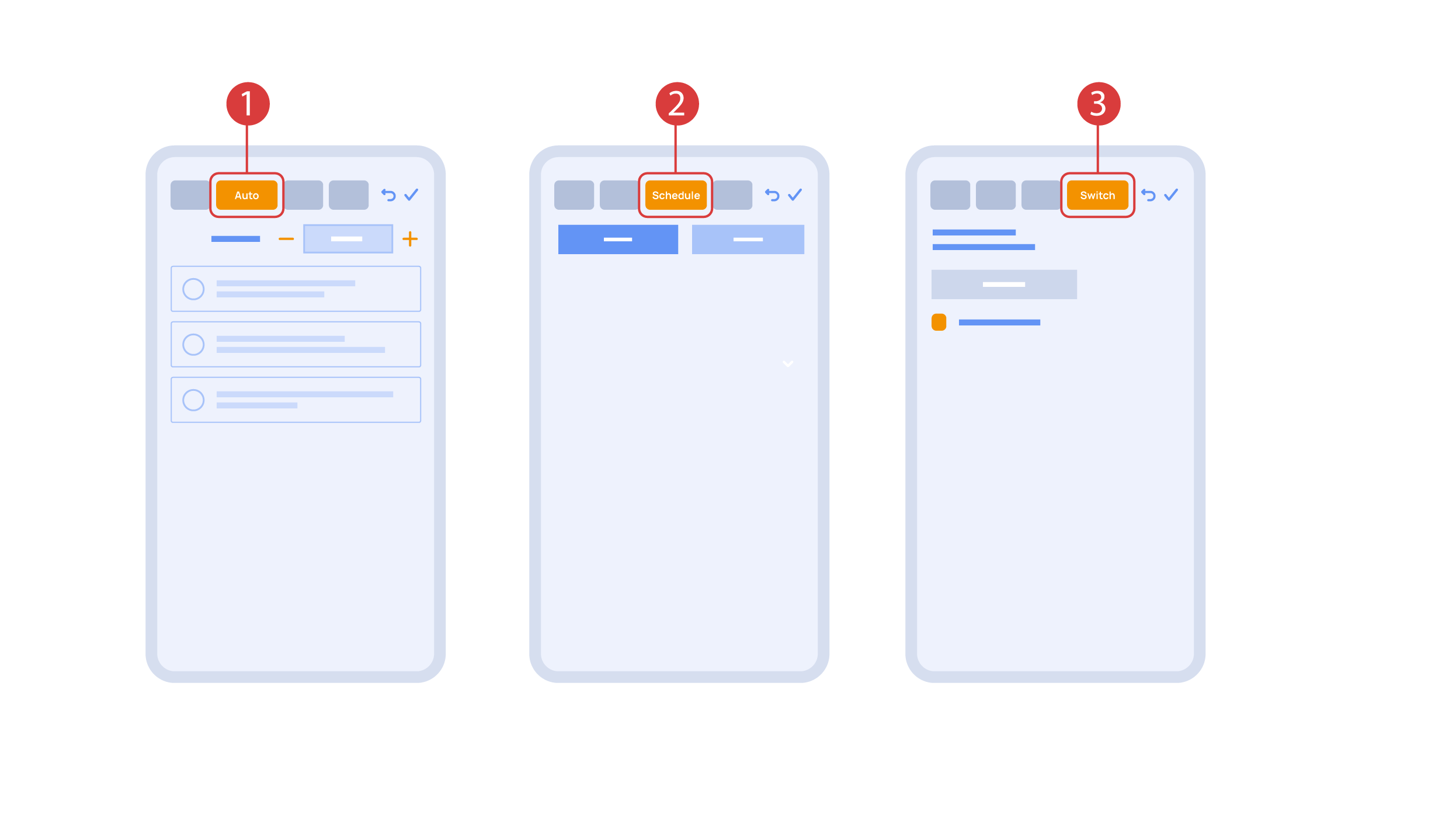
‘Auto’ section ① lets us activate the automation with a few clicks, as well as set up its parameters.
In the ‘schedule’ section ②, you can determine the schedule when the given element will turn on or off, including by using the time of the setting and rising of the sun.
The ‘Switches’ tab ③ lets you bind a button to control the executor.
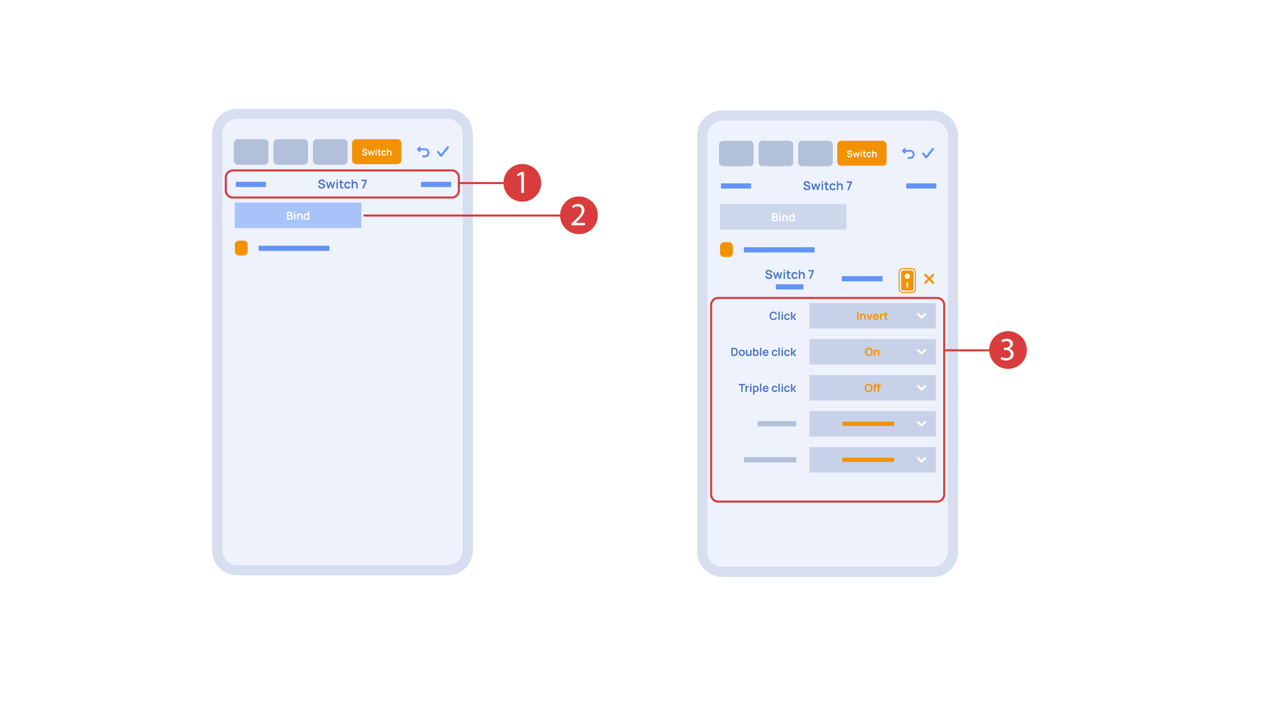
In order to do this, ① we press the button we need to bind. The system displays it, after which we press ‘Bind’② and save the changes. Now this button controls the executor
The ‘Switches’ tab ③ also features additional button setup options. For example, we can program the executor to be controlled with a double or triple click of a button, as well as define an action performed by this, for example ‘only turning on’ or ‘only turning off’ an executor. In this case we are setting up the button to do the following: one click will cause the lamp to toggle, a double click will turn it on and a triple click will turn it off. In this way a single button can perform up to five different actions.
Let’s also set up basic automation of turning an executor on or off with the help of a motion sensor.
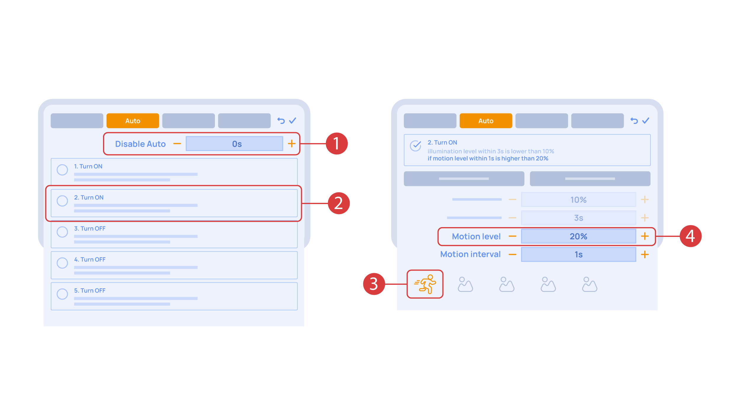
The ‘Auto period’ ① option sets the time for which the automation is disabled after an executor is manually controlled.For our demonstration purposes, we will set it to zero.
Then we will activate the automation ② to turn on the executor when motion is detected. We choose the motion sensor ③ and the level of motion ④. We can also choose a light sensor and its parameters.
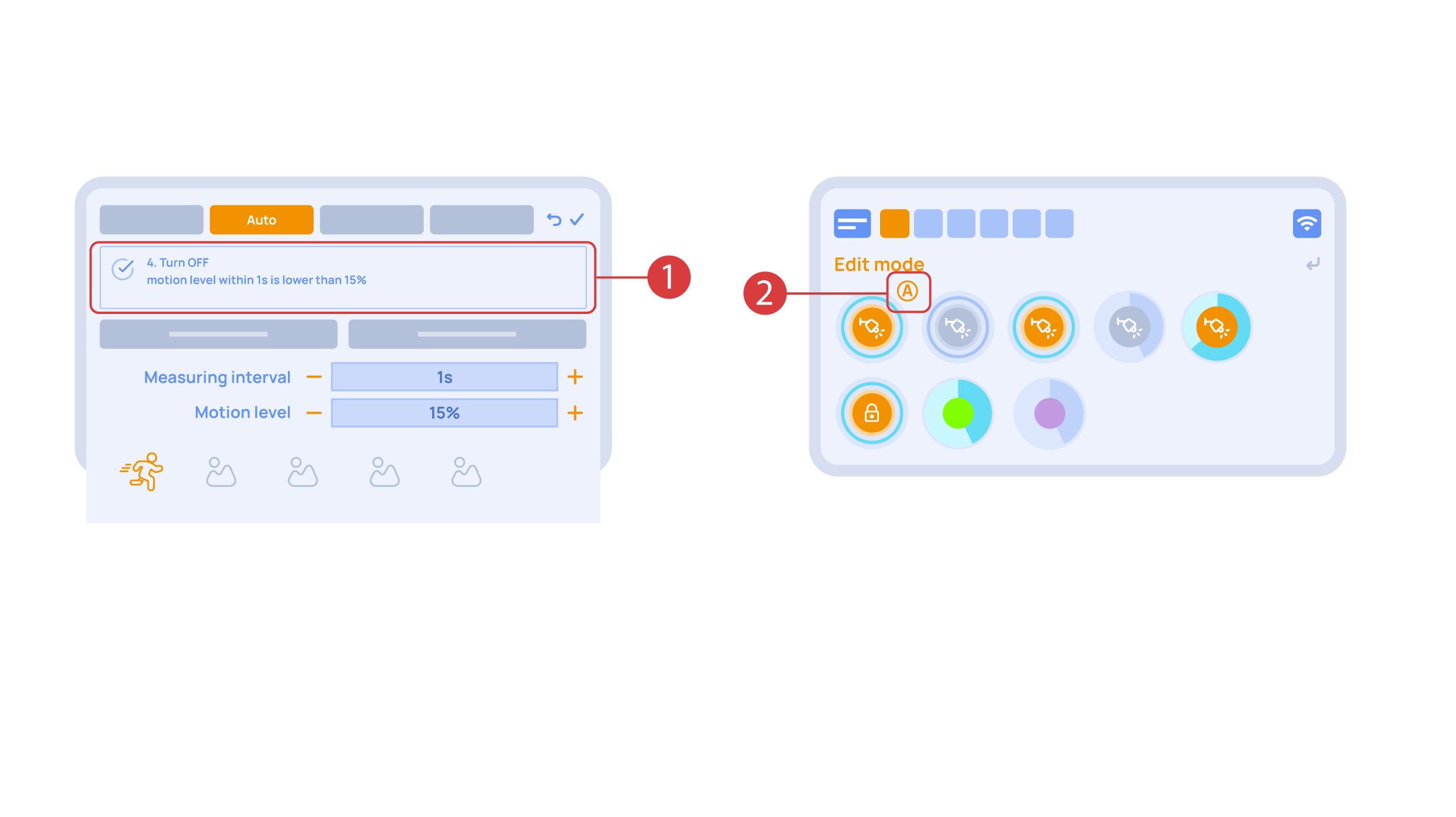
Now we will activate turning off ① of an executor if there is no motion: we choose the same sensor, set a lower threshold and a minimal time.Save the changes.
The extra ‘A’ icon ② will be added to the executor icon, meaning that automation has been set up for it. Now the lamp will be turned on when motion is detected and instantly turned off when no motion is detected.
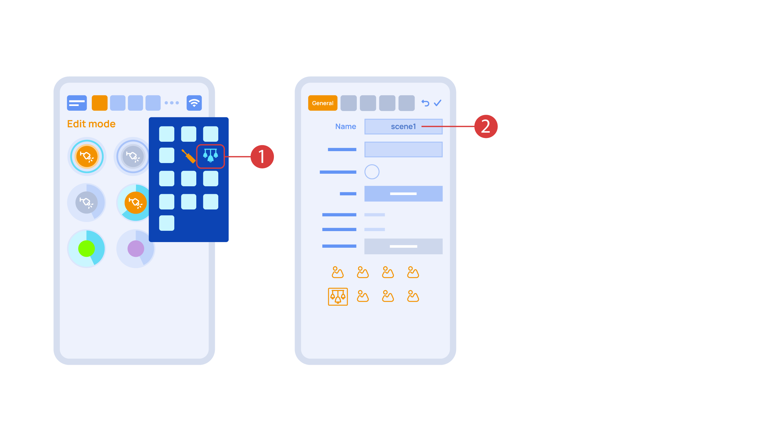
Let’s create a light scheme. For this we need to select the appropriate item in the additional menu ①. Give the light scheme a name ②.
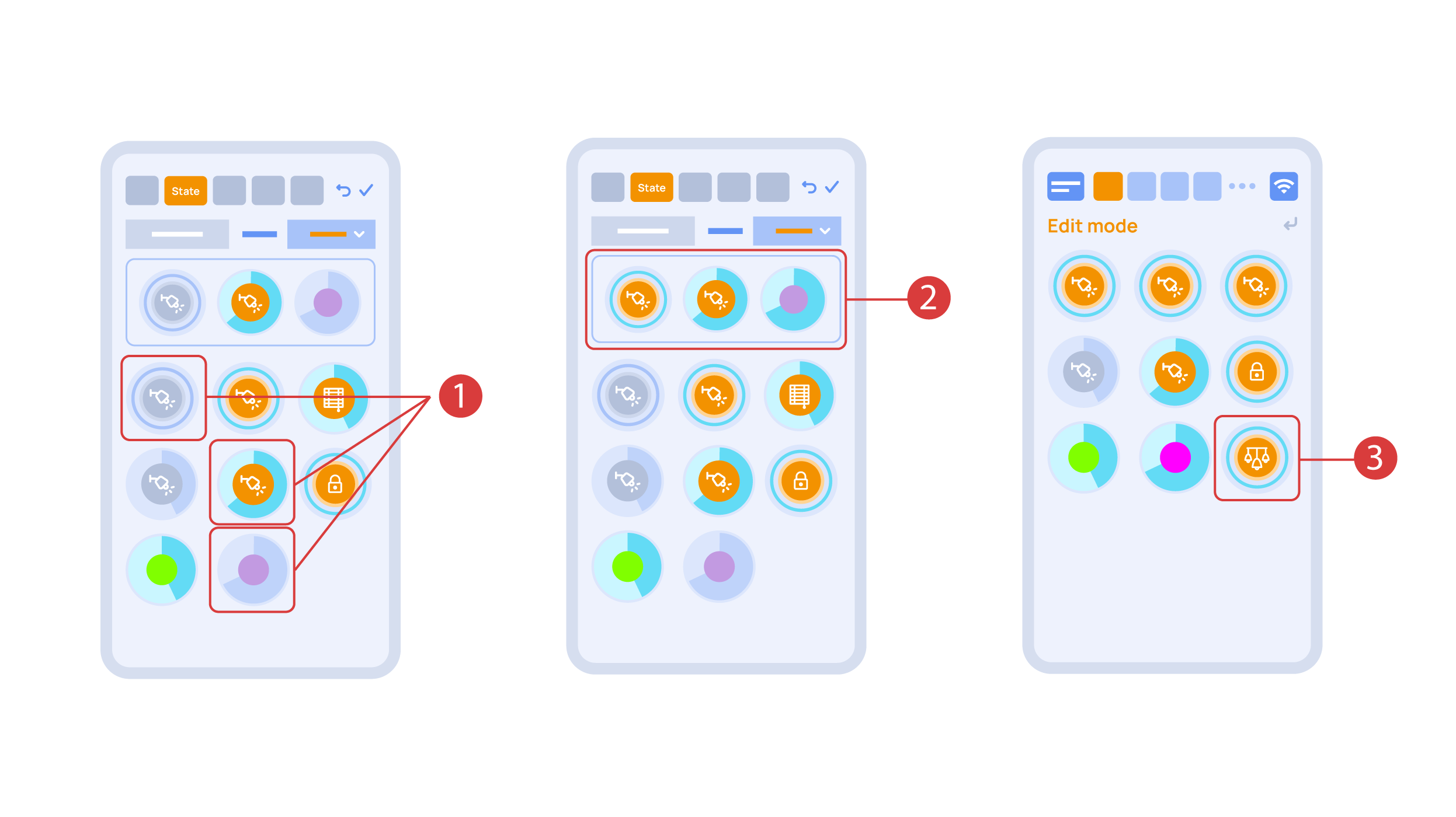
In the ‘State’ tab, use a long press to add the lights we want to use into the light scene ① and set up their state ②. ‘Auto’, ‘Schedule’, ‘Switch’ tabs are the same for all the executors.
Save the changes and we are able to use the newly-created light scheme ③ immediately.
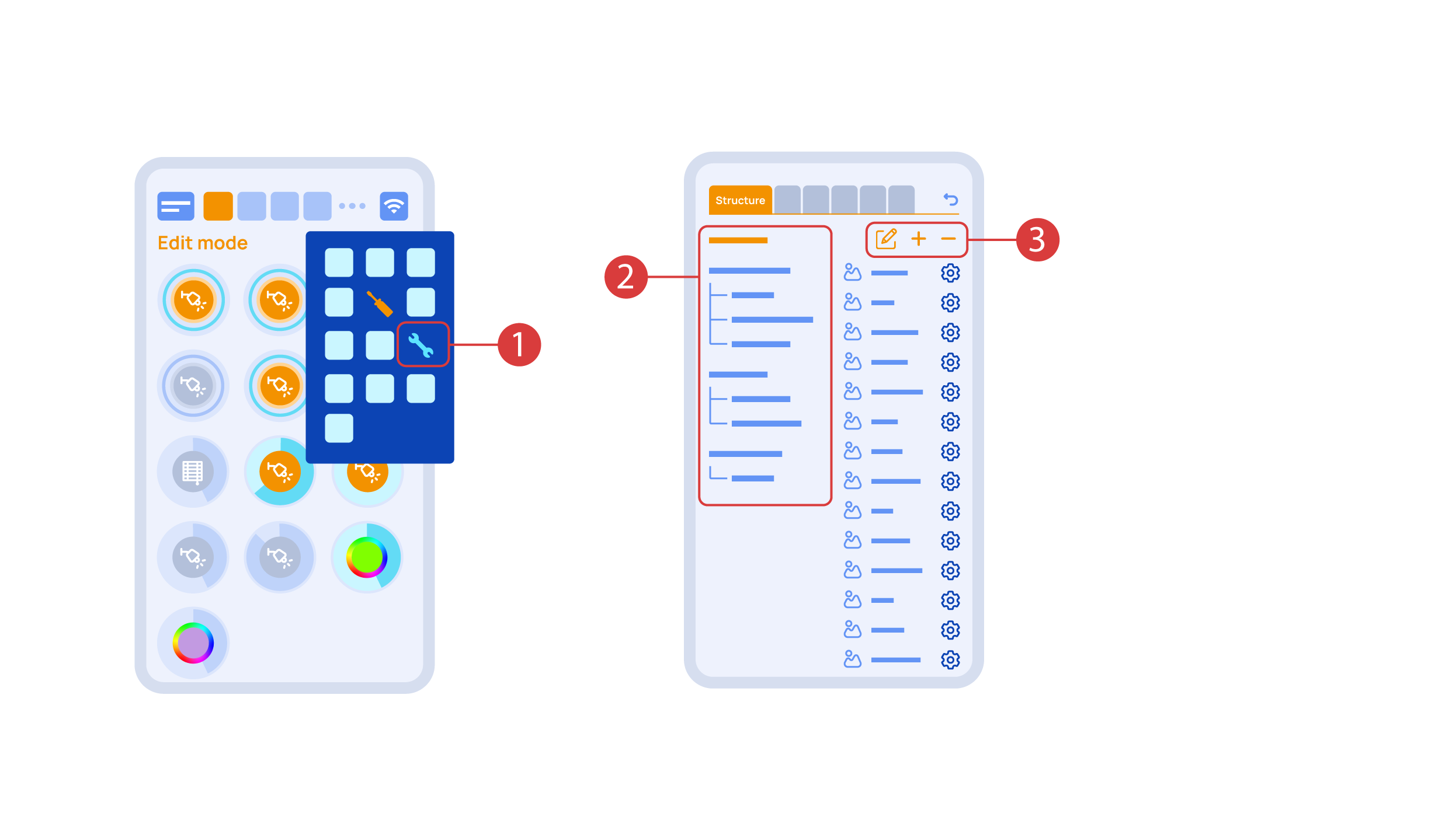
While you are in the Edit Mode, there is a ‘Setup’ ① icon in the additional menu.
Here in the ‘Structure’② tab we can see all the areas.
We can create new ones ④, rename them and move the elements around.
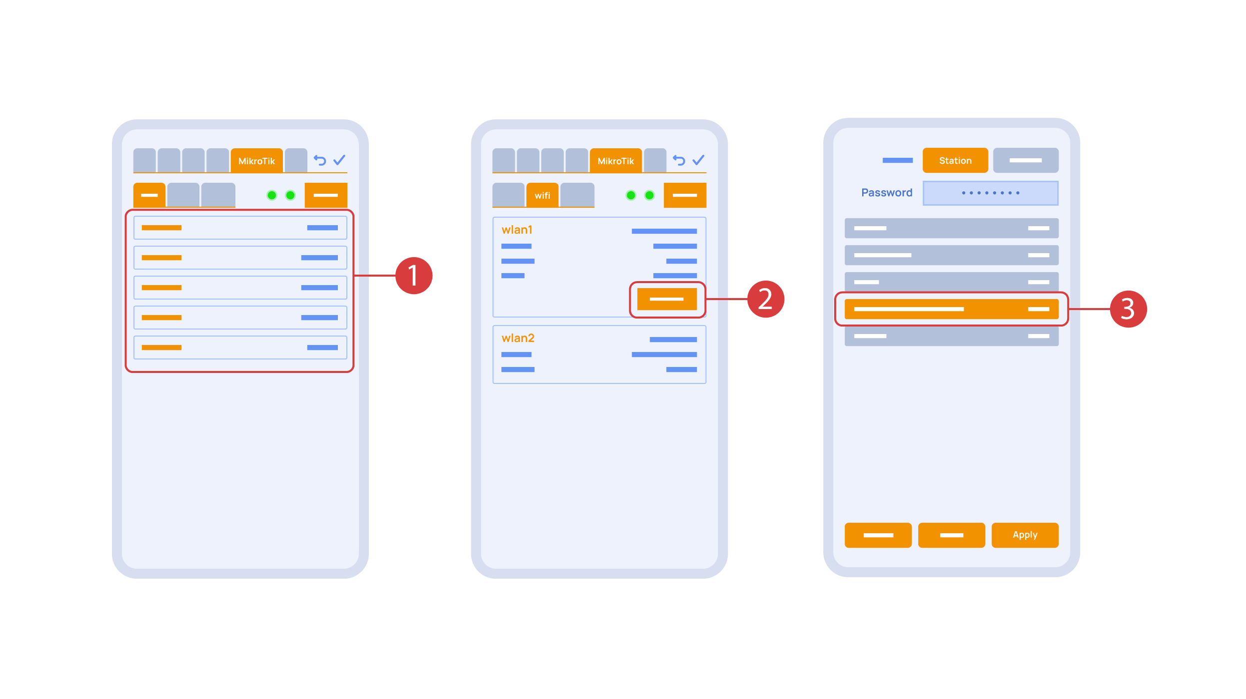
In the ‘Mikrotik’ tab ① you can see the current parameters of your router, which you can also connect to your local Wi-Fi network.
In order to do this, enter the Wi-Fi sub-menu, click the wlan1 interface configuration ②, after which choose the ‘station’ mode, choose a Wi-Fi network out of the list ③ of available ones and enter the connection password.
In the ‘Backups’ tab ① you can see the list of saved configurations, which can be restored if necessary.

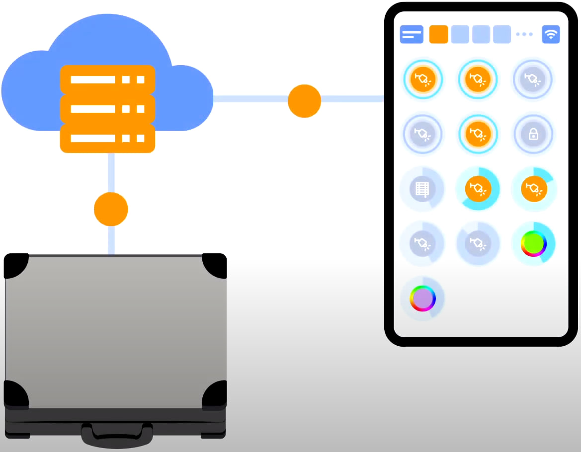
For cloud access to the device, you do not need any extra settings. The app detects the absence of the system in your local network and automatically establishes the connection via the cloud.
We thank you for watching this tutorial! If you have questions or need extra help, please do not hesitate to refer to our technical support team. See you in the next episodes!