Quick Start Guide
Hurtig start/udpakning.
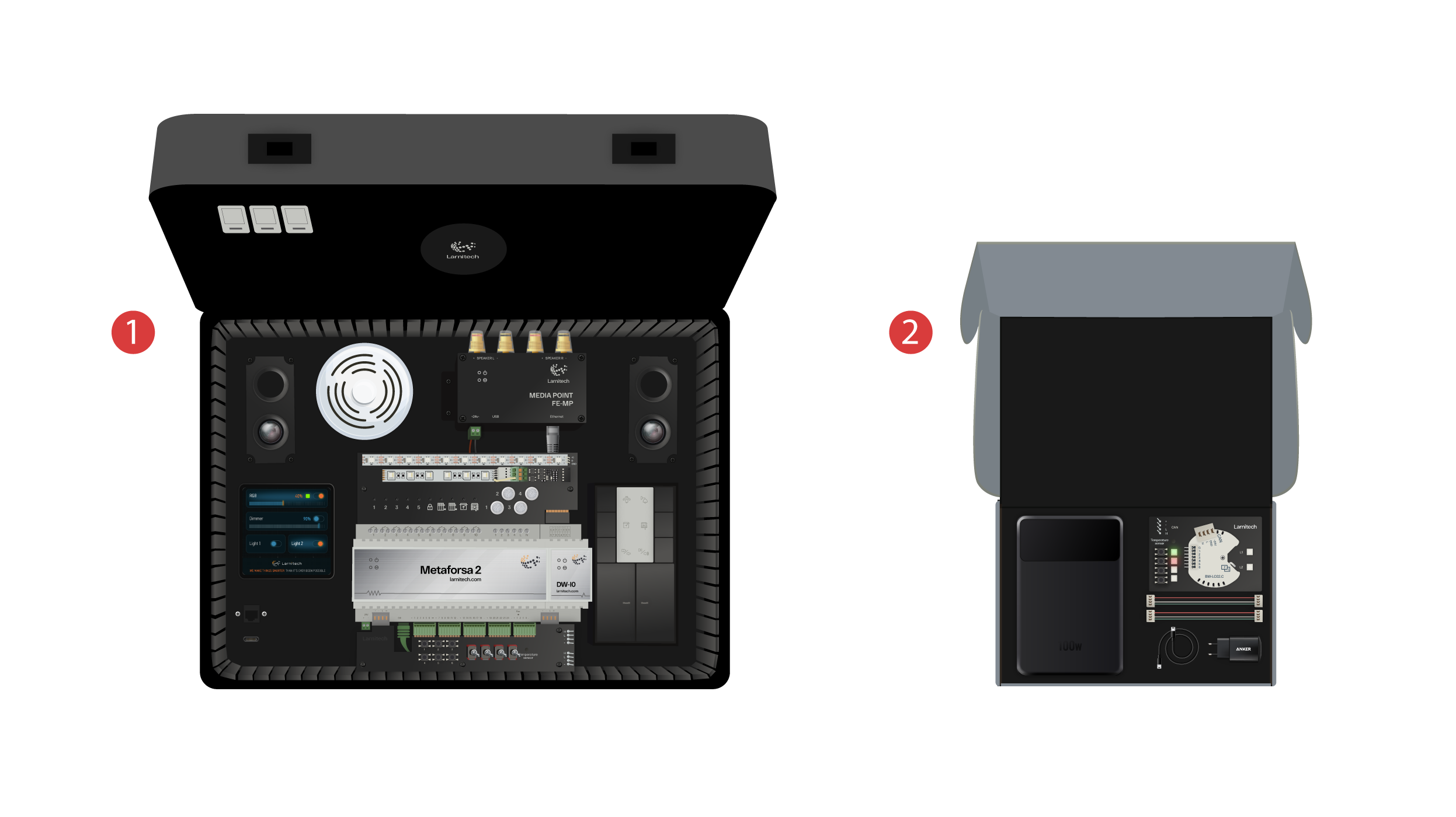
Vi byder alle velkommen på vores kanal! Denne video er en guide til, hvordan du hurtigt og ubesværet sætter Larnitech-systemet op. Opsætningen sker ved hjælp af en demonstrationskuffert. Et træningssæt indeholder en demonstrationskuffert ① og en kasse med flere ekstra ting ②.
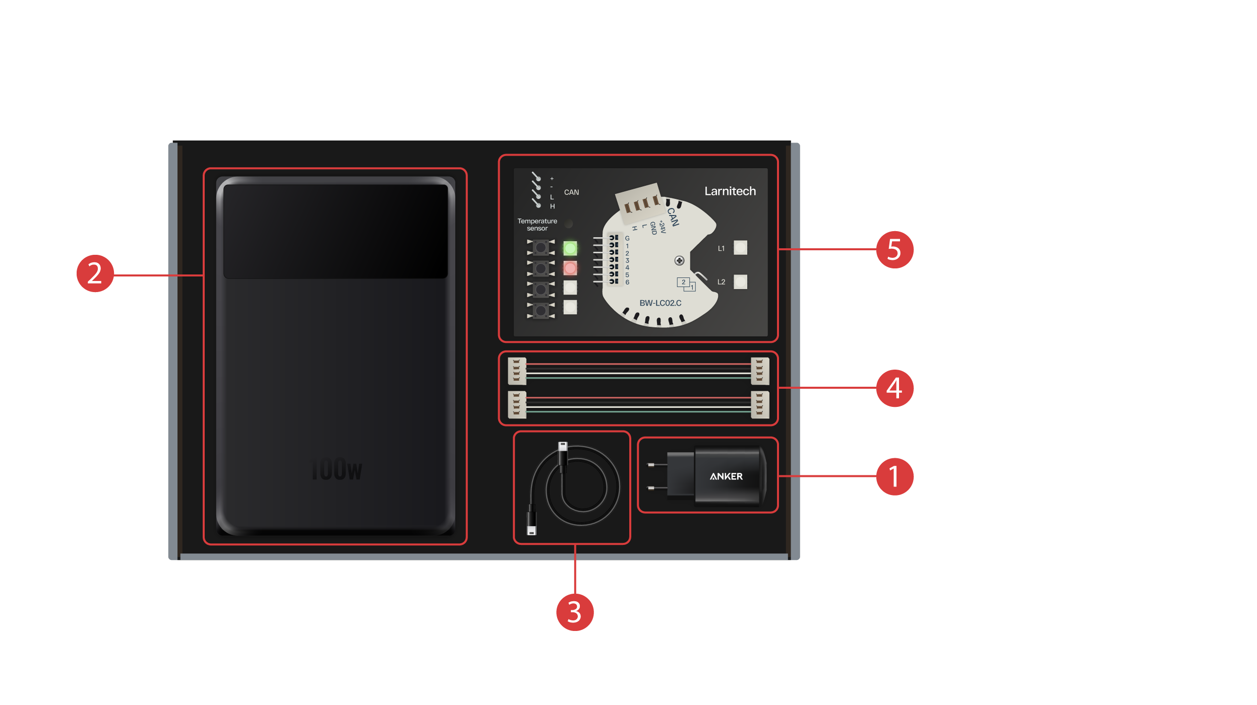
Kassen indeholder følgende:
① - En strømforsyningsenhed med Type-C USB-port, der understøtter Power Delivery-teknologien;
② - En powerbank med display og Type-C-udgangsport, som kan bruges til at give strøm til demonstrationskufferten;
③ - Type-C-kabel med indikator for strømforbrug;
④ - 2 CAN-buskabler;
⑤ - Demonstrationskort med et BW-LC02-modul med 2 LED-lys, 4 knapper med baggrundsbelysning og en temperaturføler tilsluttet.
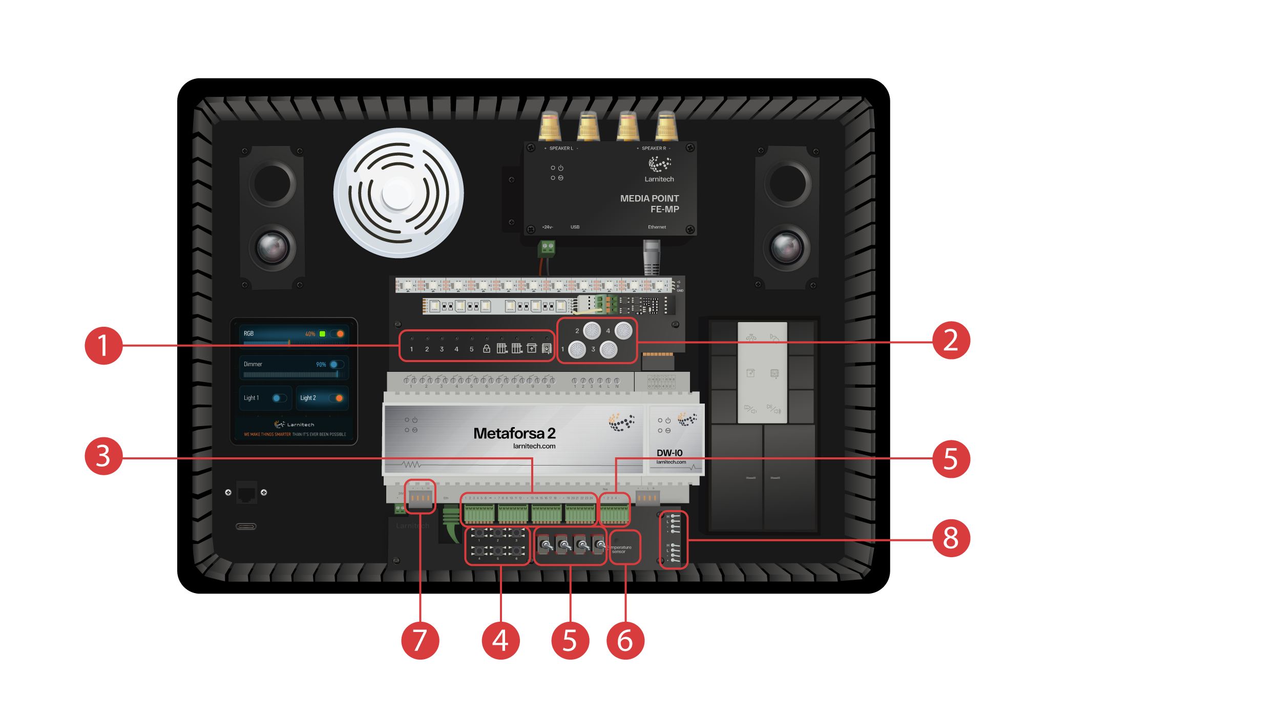
Demonstrationskufferten indeholder følgende elementer: 'Metaforsa 2'-modulet.
'Metaforsa 2' har:
① - 10 relækanaler med tilsluttede LED-lys, der viser deres aktuelle status;
② - 4 dæmpbare kanaler med dæmpbare LED-lys forbundet til dem;
③ - 24 indgangskanaler med 6 knapper ④ og 4 kontakter ⑤ forbundet til dem for at efterligne forskellige sensorer;
⑥ - Indgangskanaler til temperatursensorer med en sensor tilsluttet;
⑦ - CAN-bus til tilslutning af ekstra enheder. Andre moduler i demonstrationskassen er forbundet til den, samt 2 porte ⑧ til tilslutning af eksterne enheder;
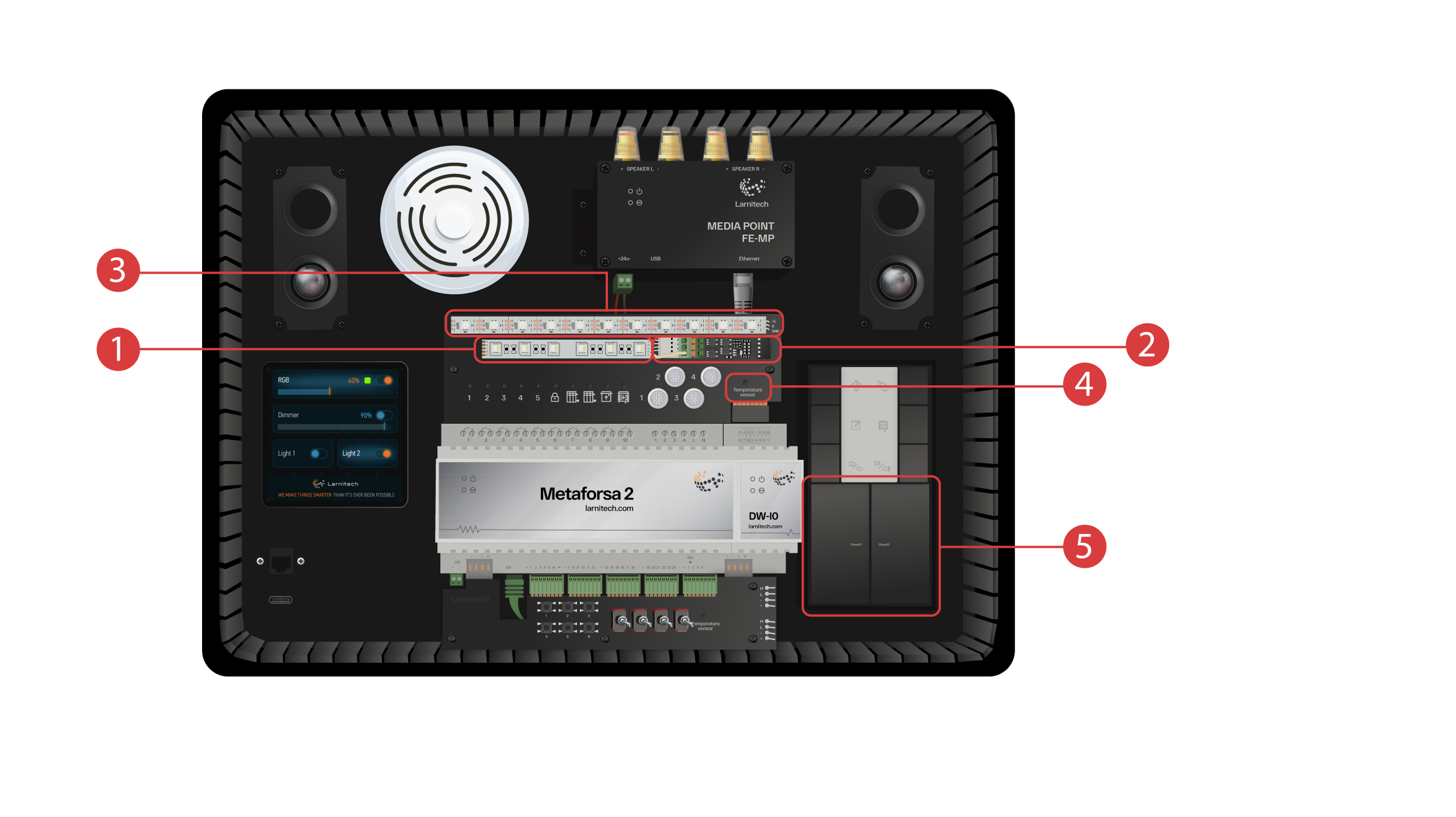
DW-IO modul
Dette modul har 14 universelle indgangs-/udgangskanaler med følgende elementer forbundet til dem:
① - 4-kanals RGBW-strip, tilsluttet via strømforstærkeren AMP5V-4 ②;
③ - En strimmel med adresserede LED-lys. Hvert af disse LED-lys kan lyse med sin egen individuelle farve;
④ - Temperatursensor;
⑤ - Og to knapper med baggrundsbelysning.
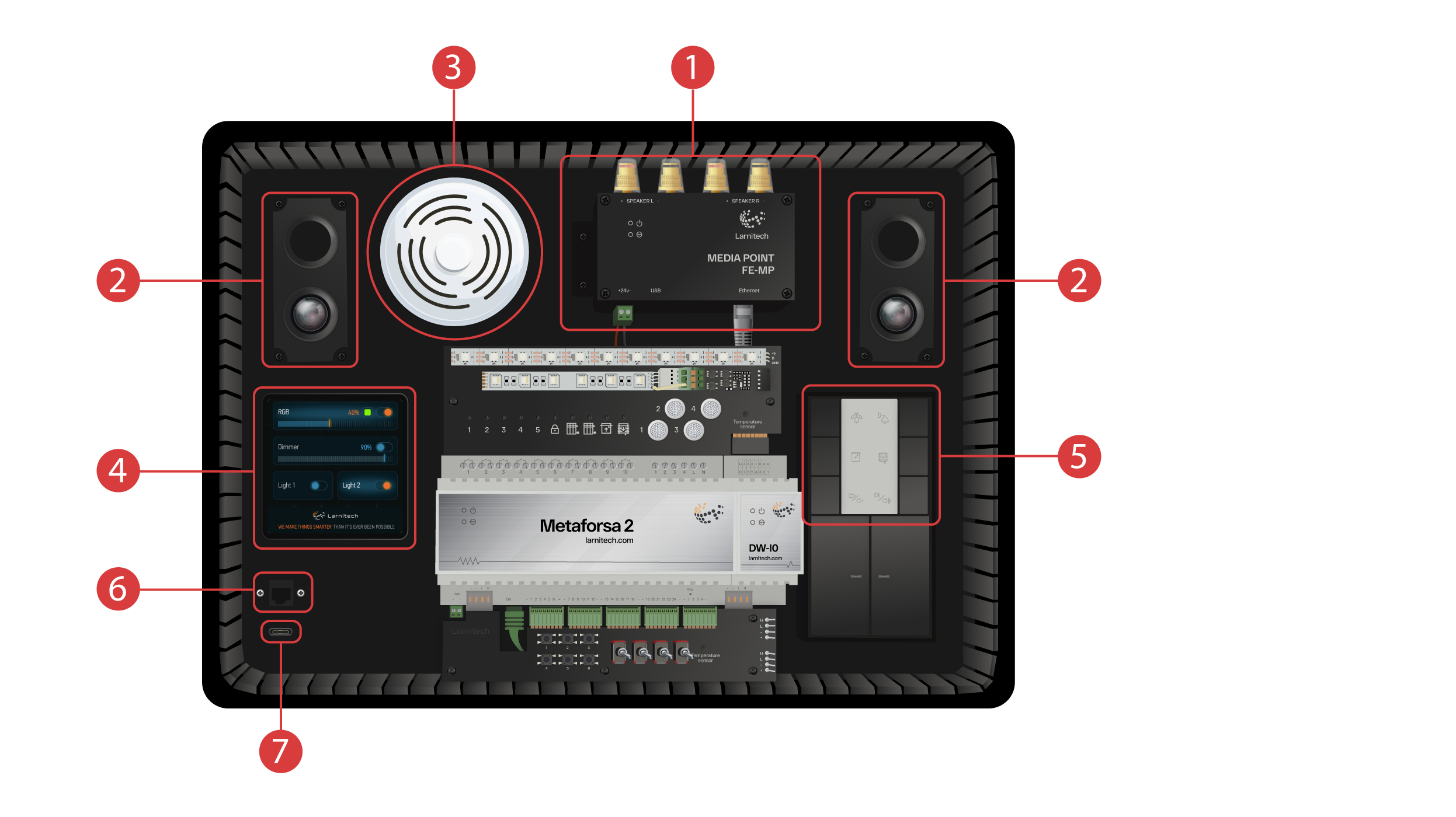
Demonstrationskufferten indeholder også følgende:
① - et Media Point FE-MP ② med to højttalere;
③ - En seks-i-en CW-CO2-sensor, som måler: Niveau af bevægelse, Belysning, Temperatur, Fugtighed, Niveau af CO2 og som har en infrarød sender.
④ - et 4-tommers sensorpanel LCP4, som kan vise enten et almindeligt interface eller et interface, der er tilpasset til vægpaneler.
Inde i kabinettet er der et knapstyringsmodul BW-SW24, som har et 24-volts JUNG-tastatur ⑤ med seks knapper tilsluttet.
Og en Wi-Fi-router, som kan forbindes til internettet enten via en Ethernet-port ⑥ på kabinettets frontpanel eller via et tilgængeligt Wi-Fi-netværk.
Til strømforsyningen er der en Type-C-port ⑦, som er placeret på frontpanelet.
Alt det udstyr, der er installeret i demonstrationskufferten, er drevet af 20 volt, hvilket er helt sikkert for brugeren.
Tilslut strømkablet og Ethernet-kablet. Hvis du ikke har mulighed for at forbinde via Ethernet, vil vi senere i denne video vise, hvordan du forbinder den indbyggede router til dit Wi-Fi-netværk.
For at komme videre skal Larnitech-appen være installeret på din smartphone eller tablet. Scan bare den første QR-kode fra toppen af din kuffert.
Hvis forbindelsen ikke oprettes automatisk efter installation og start af applikationen, skal du oprette forbindelse til Wi-Fi-netværket 'Larnitech_case_5G' ved hjælp af din mobile enhed. Start derefter applikationen, og scan den første QR-kode i afsnittet 'Connections'.
Det kan være nødvendigt at slå dataoverførsel fra på din mobile enhed, hvis demonstrationssættet ikke er forbundet til internettet.

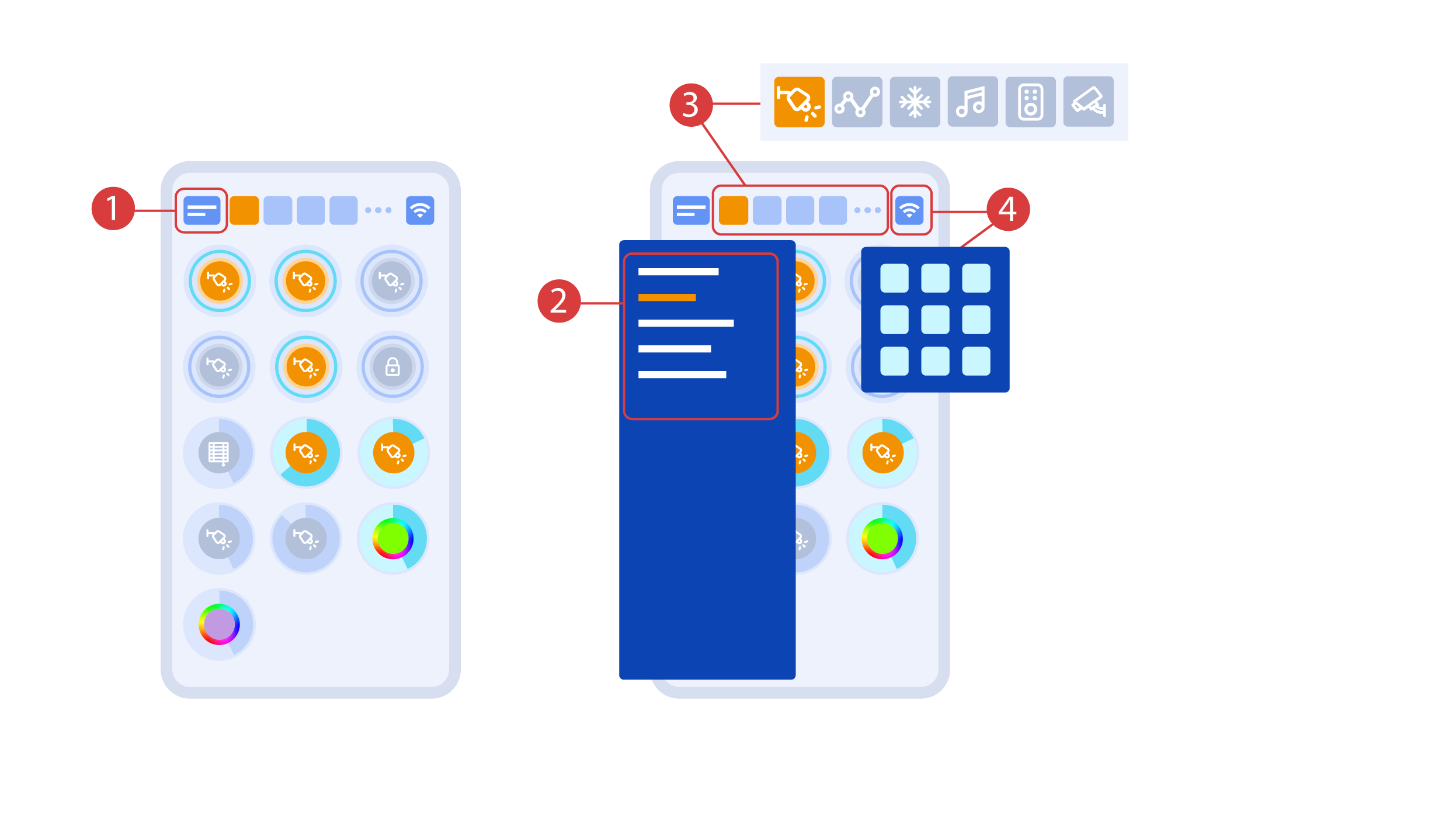
Appens hovedskærm har flere nøgleelementer. I øverste venstre hjørne er der menuen 'area select' ①.
Bare klik på et af de tilgængelige områder for at administrere det ②.
Derefter er der ikoner, som lader dig vælge eksekutorer, sensorer, klima, multimedie, fjernbetjeninger og kameraer ③. I højre hjørne er der et ikon for den ekstra menu ④. Inde i ikonet kan du også se status for den aktuelle forbindelse.
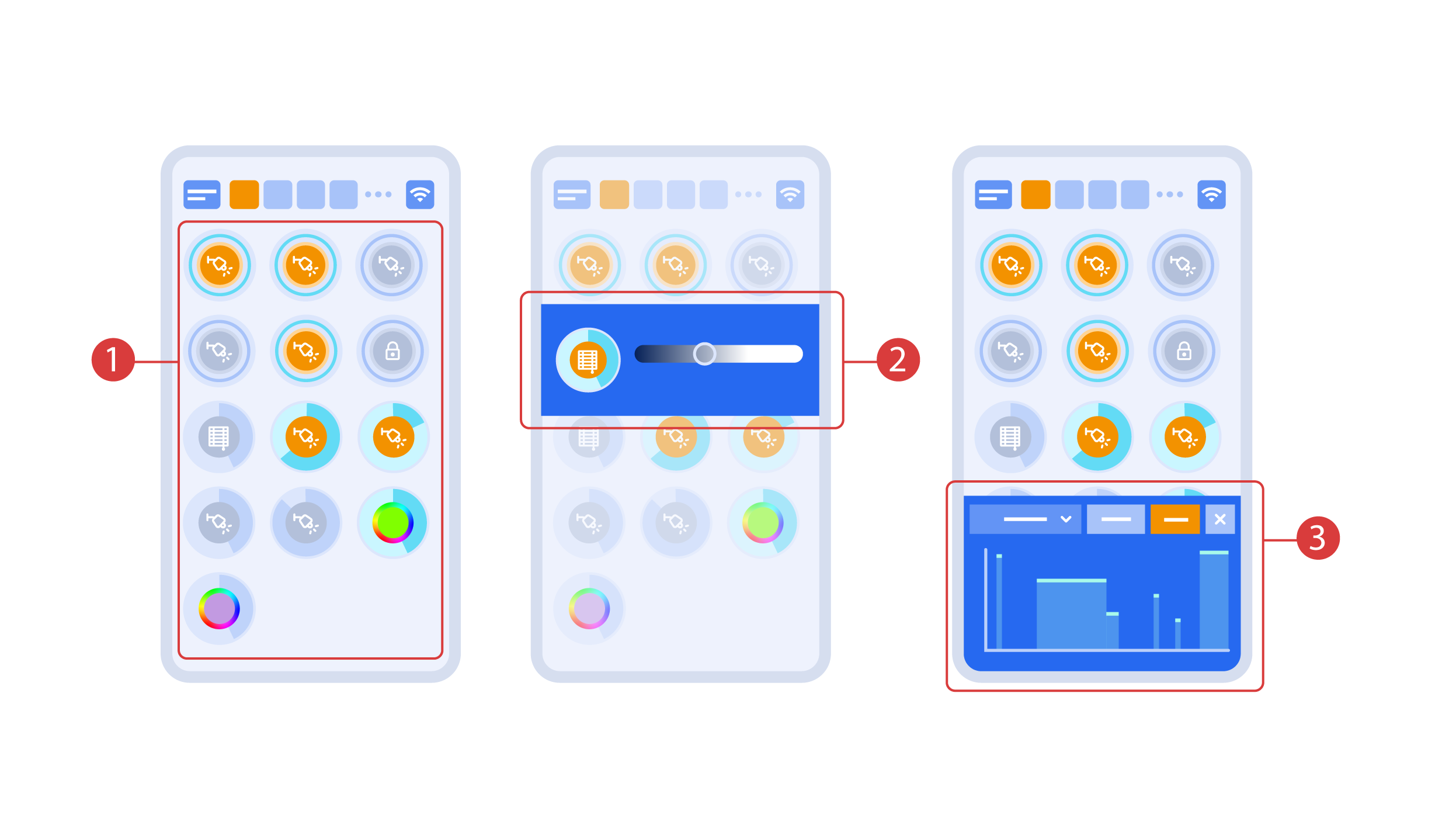
Du tænder og slukker for eksekutorerne ① med et enkelt klik. For at ændre lysniveau ②, lysfarve eller persiennernes position skal du bruge et dobbeltklik. For at få adgang til statushistorikken ③ for denne eksekutor eller sensor skal du trykke på ikonet og holde det nede i et sekund.
Et kort tryk på de fysiske knapper på panelet tænder eller slukker lyset. Tryk på knappen og hold den nede for at ændre lysstyrken.
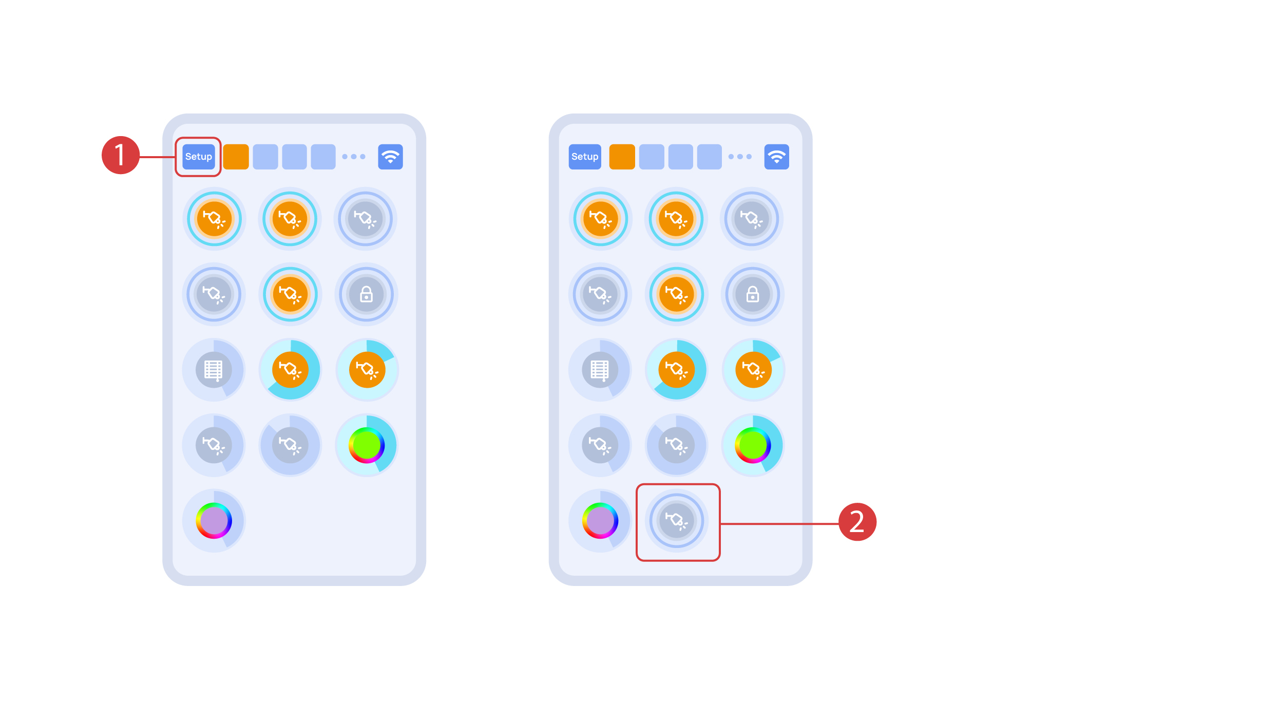
For at demonstrere Plug and Play-funktionen åbner vi eksekutørerne i Setup-området ① g tilslutter modulet til CAN-bussen. Systemet registrerer automatisk det nye modul og føjer det til 'Setup'-området ②, hvor vi kan styre det nye modul med det samme.
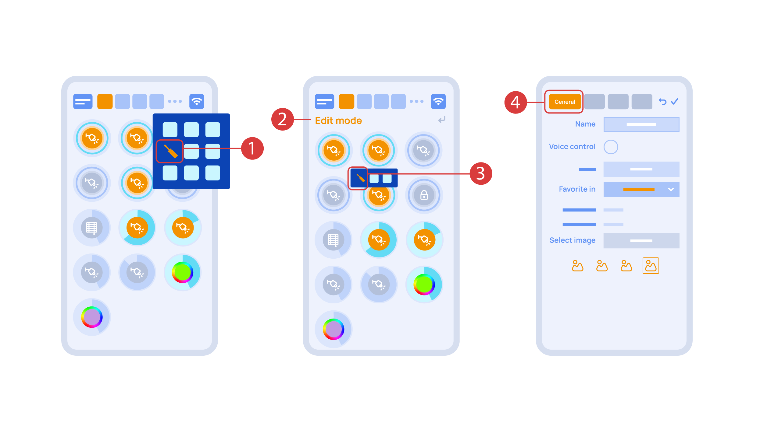
Now we can set up these executors. In order to do this, enter the additional menu ① and activate the edit mode, by pressing the appropriate icon .
Now we are in the edit mode ②, which can be seen from the appropriate notification in the top part of the screen. In this mode, when we press and hold an icon, we can move it among other elements and place it into another Room by placing it in the Area-choosing Menu and then choosing the area that we need. A long press ③ of the element starts the menu, from which we set up the current element.In the ‘General’ ④ section we can change the name of the element, add a voice command for it, change an icon or add the element to ‘Favorites’.
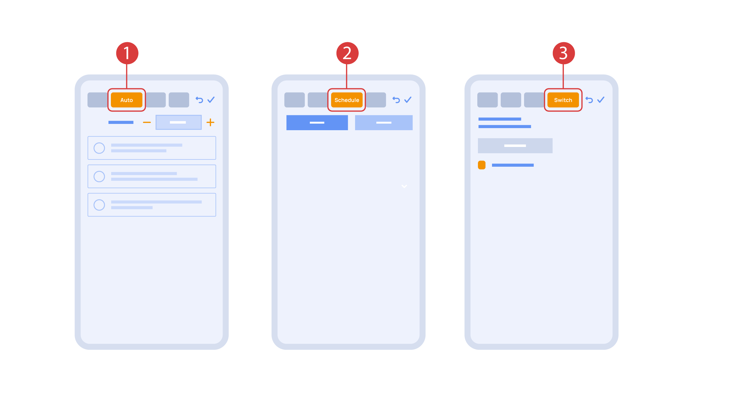
‘Auto’ section ① lets us activate the automation with a few clicks, as well as set up its parameters.
In the ‘schedule’ section ②, you can determine the schedule when the given element will turn on or off, including by using the time of the setting and rising of the sun.
The ‘Switches’ tab ③ lets you bind a button to control the executor.
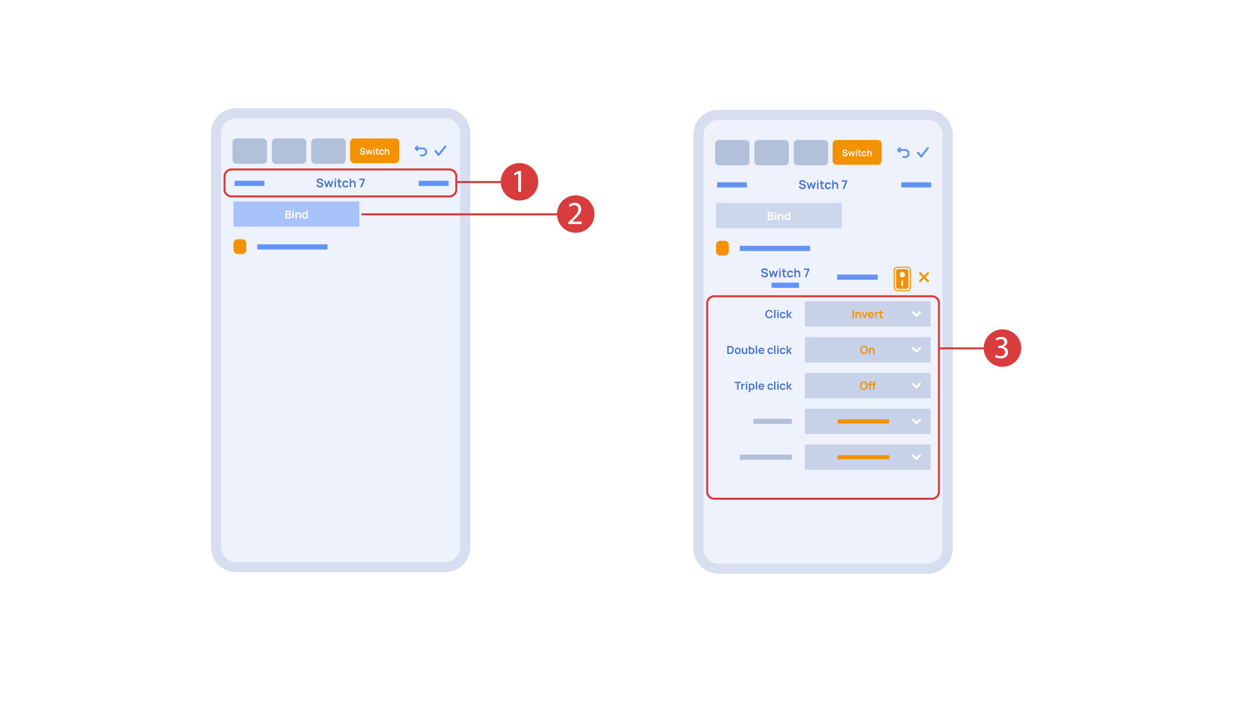
In order to do this, ① we press the button we need to bind. The system displays it, after which we press ‘Bind’② and save the changes. Now this button controls the executor
The ‘Switches’ tab ③ also features additional button setup options. For example, we can program the executor to be controlled with a double or triple click of a button, as well as define an action performed by this, for example ‘only turning on’ or ‘only turning off’ an executor. In this case we are setting up the button to do the following: one click will cause the lamp to toggle, a double click will turn it on and a triple click will turn it off. In this way a single button can perform up to five different actions.
Let’s also set up basic automation of turning an executor on or off with the help of a motion sensor.
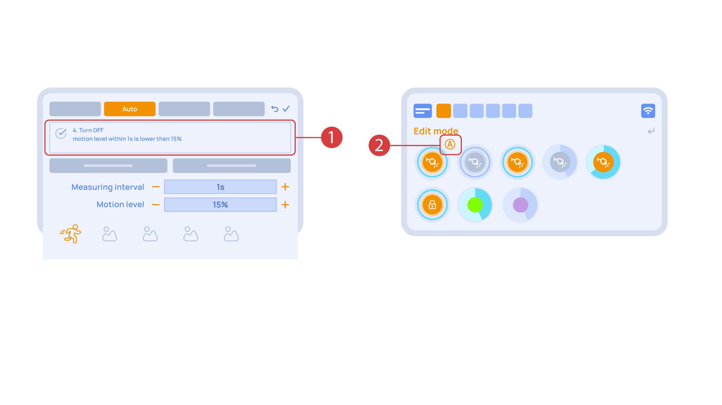
The ‘Auto period’ ① option sets the time for which the automation is disabled after an executor is manually controlled.For our demonstration purposes, we will set it to zero.
Then we will activate the automation ② to turn on the executor when motion is detected. We choose the motion sensor ③ and the level of motion ④. We can also choose a light sensor and its parameters.
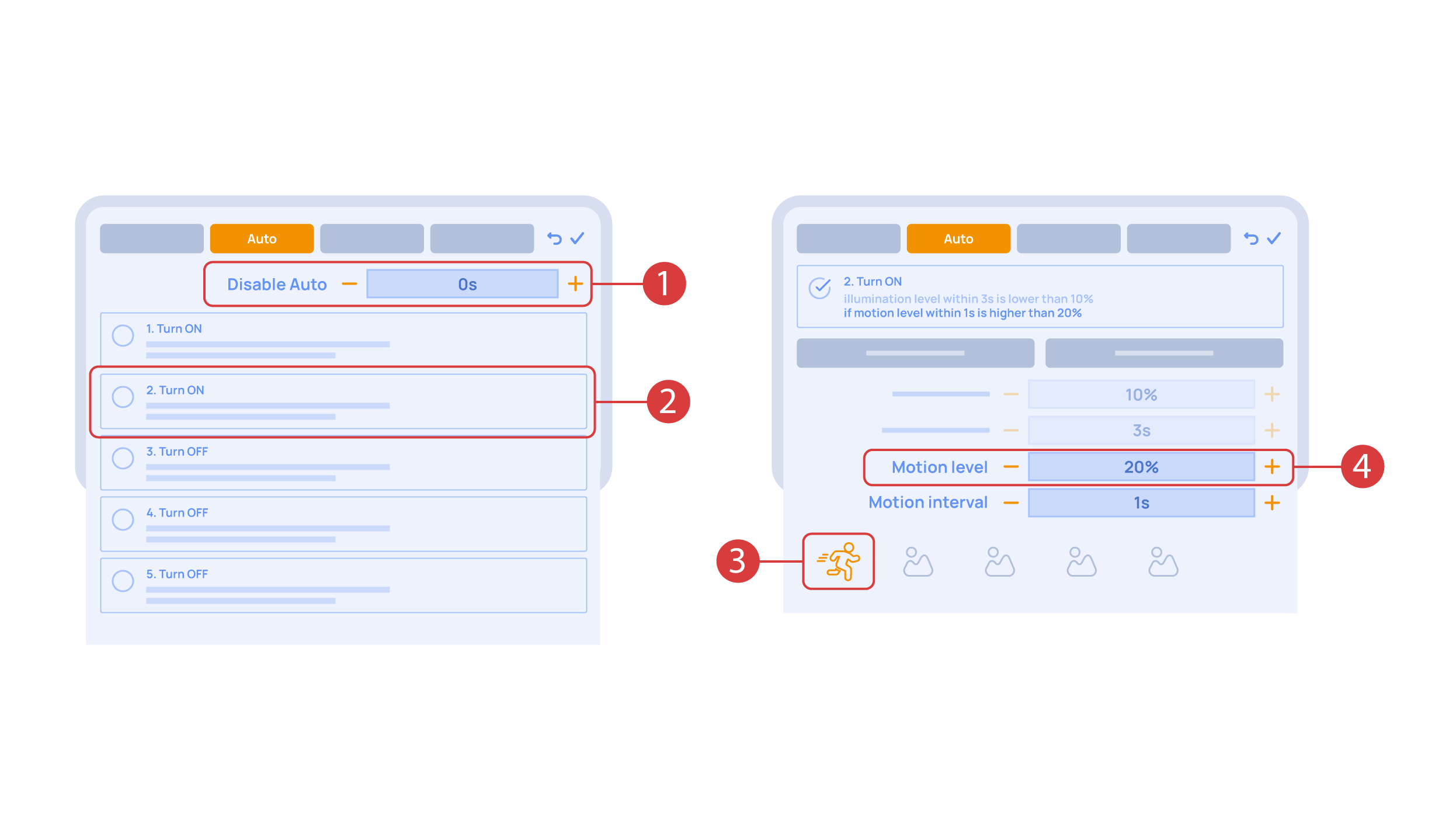
Now we will activate turning off ① of an executor if there is no motion: we choose the same sensor, set a lower threshold and a minimal time.Save the changes.
The extra ‘A’ icon ② will be added to the executor icon, meaning that automation has been set up for it. Now the lamp will be turned on when motion is detected and instantly turned off when no motion is detected.
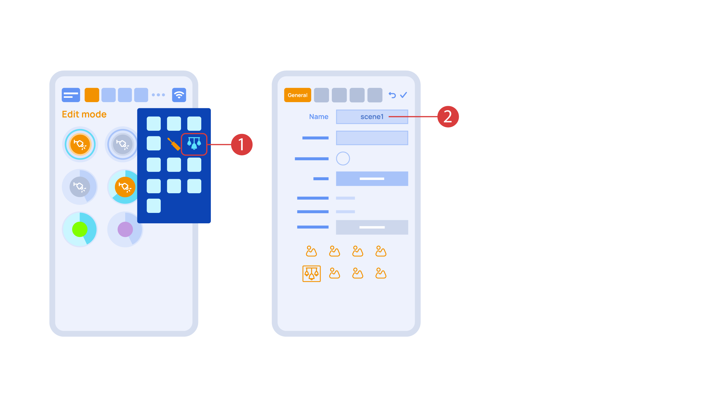
Let’s create a light scheme. For this we need to select the appropriate item in the additional menu ①. Give the light scheme a name ②.
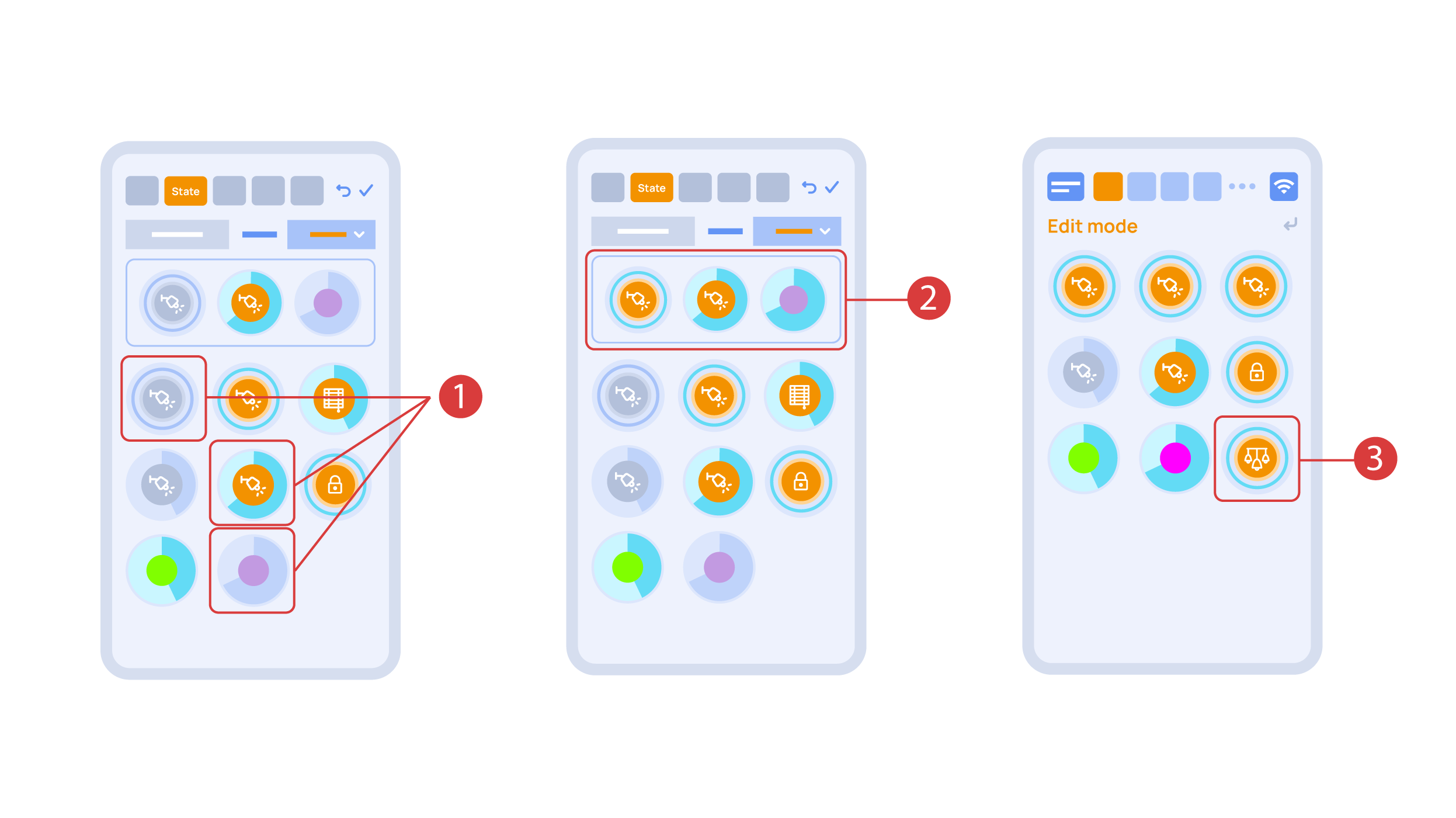
In the ‘State’ tab, use a long press to add the lights we want to use into the light scene ① and set up their state ②. ‘Auto’, ‘Schedule’, ‘Switch’ tabs are the same for all the executors.
Save the changes and we are able to use the newly-created light scheme ③ immediately.
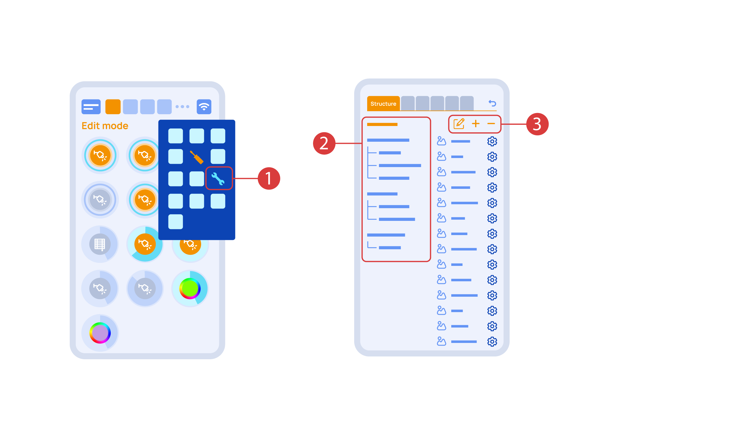
While you are in the Edit Mode, there is a ‘Setup’ ① icon in the additional menu.
Here in the ‘Structure’② tab we can see all the areas.
We can create new ones ④, rename them and move the elements around.
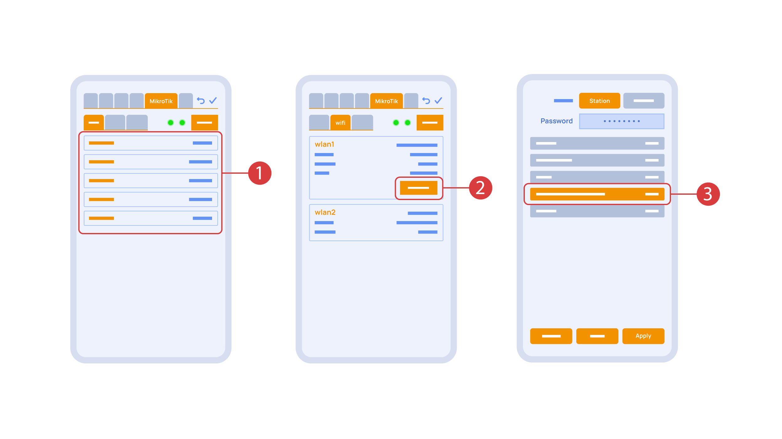
In the ‘Mikrotik’ tab ① you can see the current parameters of your router, which you can also connect to your local Wi-Fi network.
In order to do this, enter the Wi-Fi sub-menu, click the wlan1 interface configuration ②, after which choose the ‘station’ mode, choose a Wi-Fi network out of the list ③ of available ones and enter the connection password.
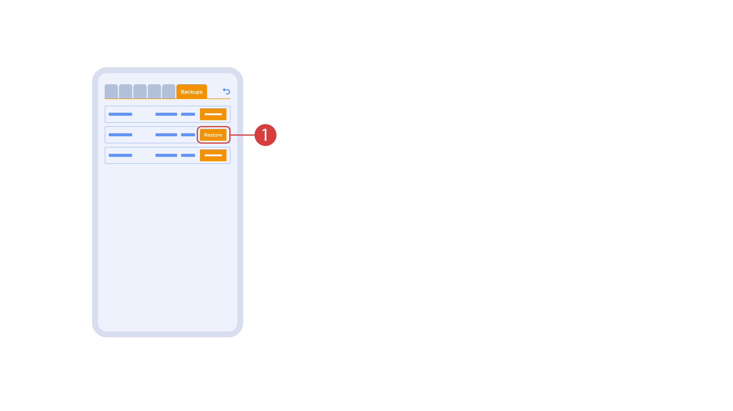
In the ‘Backups’ tab ① you can see the list of saved configurations, which can be restored if necessary.
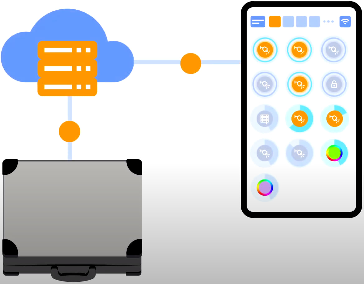
For cloud access to the device, you do not need any extra settings. The app detects the absence of the system in your local network and automatically establishes the connection via the cloud.
We thank you for watching this tutorial! If you have questions or need extra help, please do not hesitate to refer to our technical support team. See you in the next episodes!