Guía de inicio rápido
Inicio rápido/desembalaje.
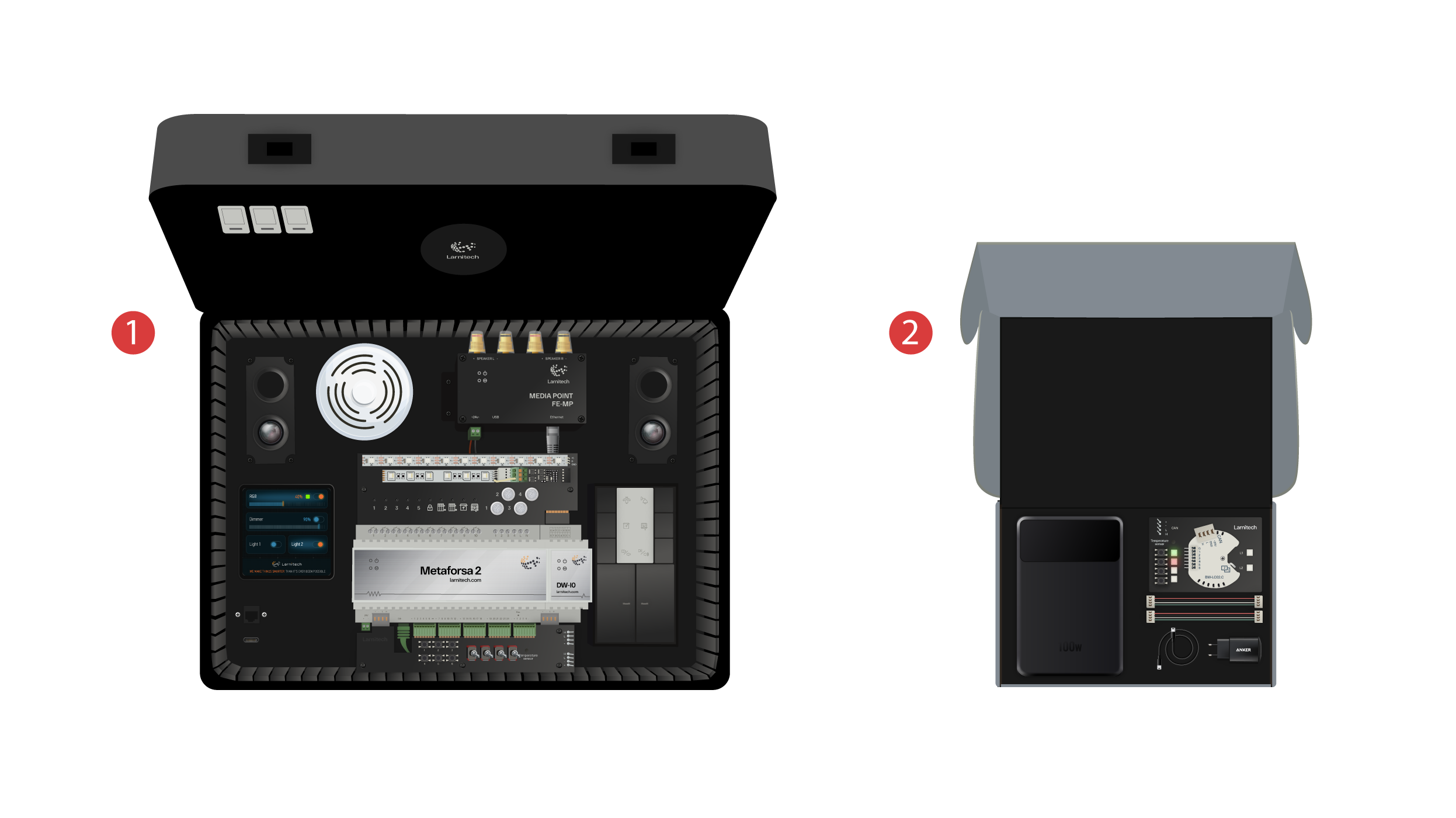
¡Damos la bienvenida a todos en nuestro canal! Este vídeo es una guía sobre cómo configurar el sistema Larnitech de forma rápida y sin esfuerzo. La configuración se realizará con la ayuda de un maletín de demostración. El set de entrenamiento incluye un maletín de demostración ① y una caja con varios artículos adicionales ②.
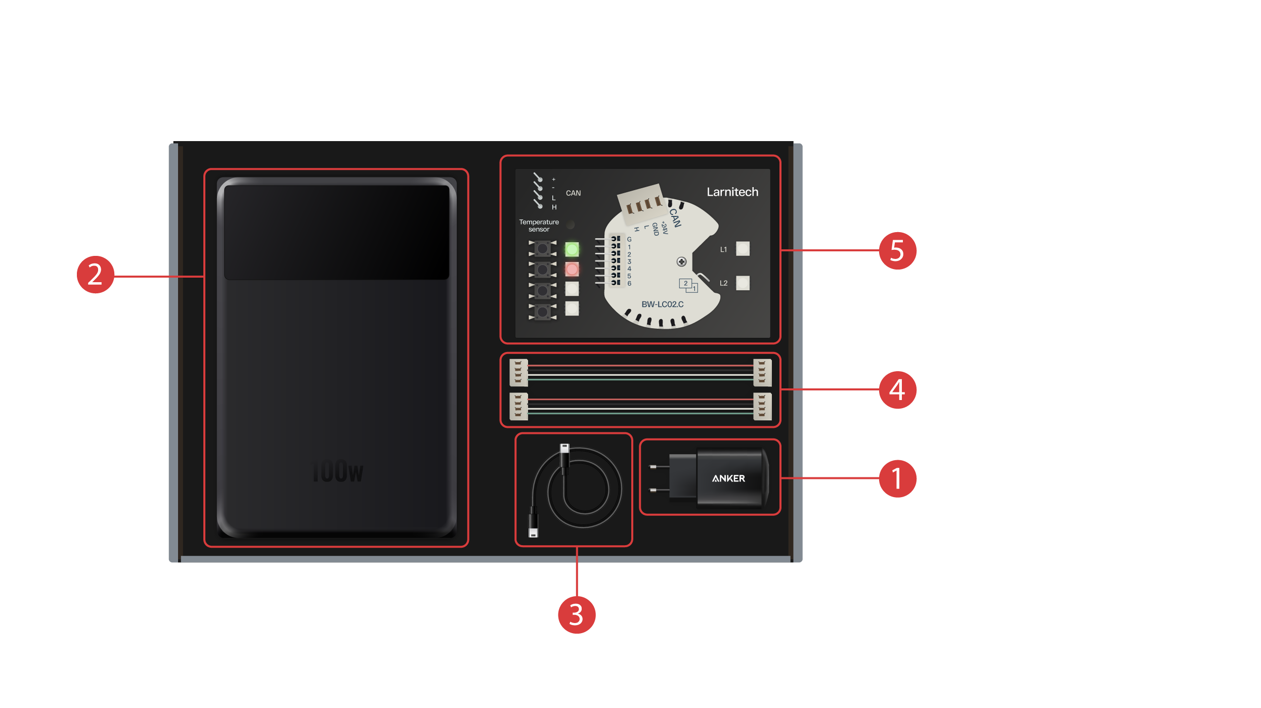
La caja incluye lo siguiente:
① - Una unidad de alimentación con puerto USB tipo C, compatible con la tecnología Power Delivery;
② - Un banco de energía con una pantalla y un puerto de salida Tipo C, que se puede utilizar para encender el maletín de demostración;
③ - Cable Tipo C con indicador de consumo de energía;
④ - 2 cables de bus CAN;
⑤ - Tablero de demostración con un módulo BW-LC02 con 2 luces LED, 4 botones con retroiluminación y un sensor de temperatura conectado a él.
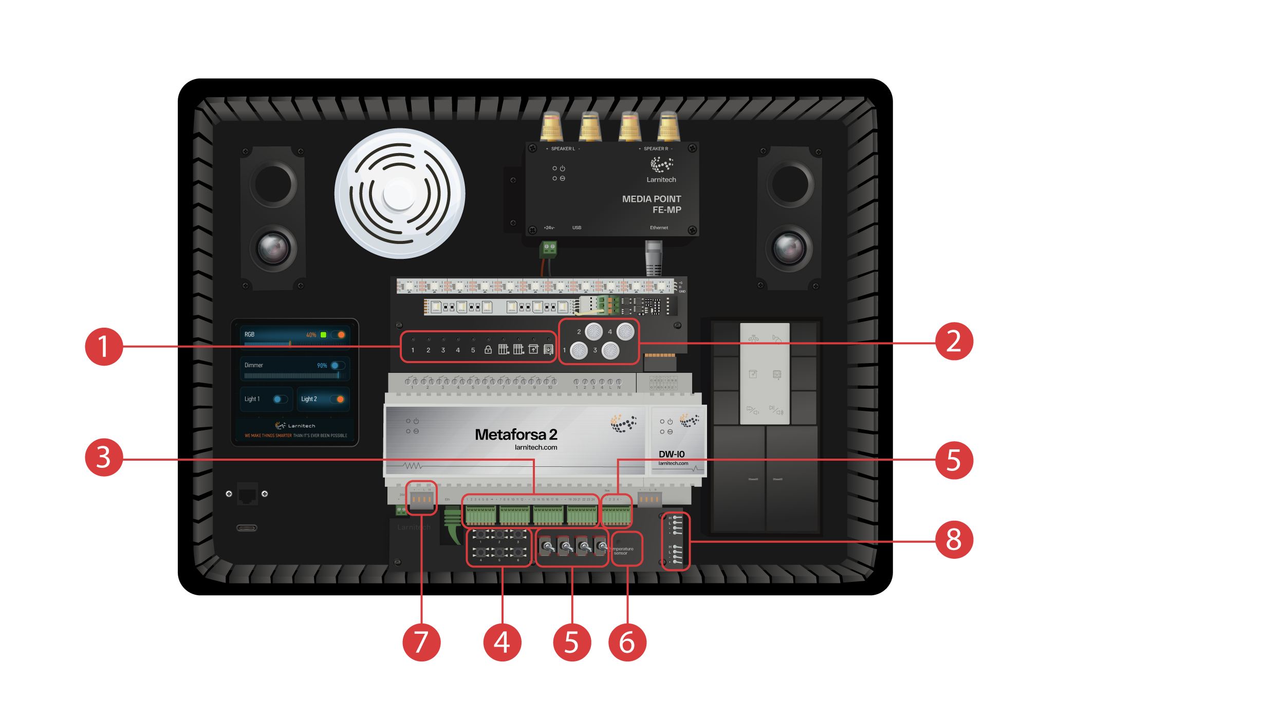
El maletín de demostración contiene los siguientes elementos: ‘Módulo Metaforsa 2’.
‘Metaforsa 2’ tiene:
① - 10 canales de relés con luces LED conectadas a ellos, indicando su estado actual;
② - 4 canales regulables, con luces LED regulables conectadas a ellos;
③ - 24 canales de entrada, con 6 botones ④ y 4 interruptores ⑤ onectados a ellos para imitar varios sensores;
⑥ - Canales de entrada para sensores de temperatura con un sensor conectado;
⑦ - Bus CAN para conectar dispositivos adicionales. Otros módulos de la caja de demostración están conectados a ella, así como 2 puertos ⑧ para conectar dispositivos externos
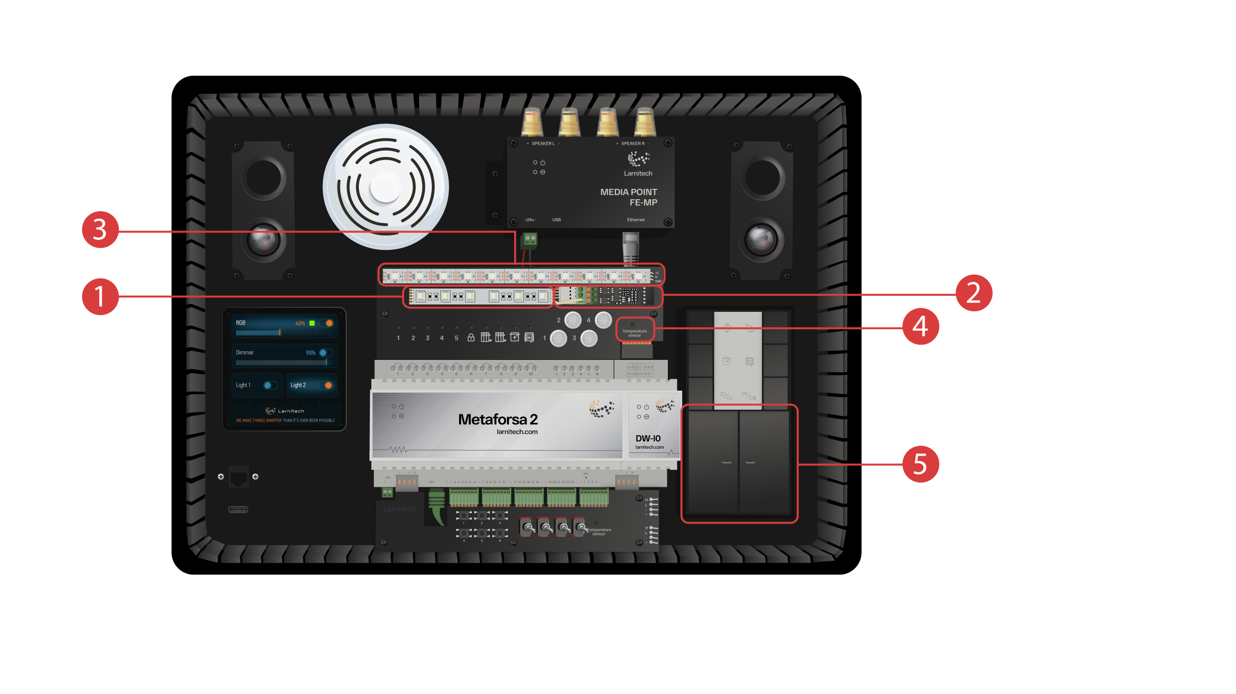
Módulo DW-IO
Este módulo tiene 14 canales universales de entrada/salida, con los siguientes elementos conectados a ellos:
① - Regleta RGBW de 4 canales, conectada a través del amplificador de corriente AMP5V-4 ②;
③ - Una tira con luces LED direccionadas. Cada una de estas luces LED puede brillar con su propio color individual;
④ - Sensor de la temperatura;
⑤ - Y dos botones con retroiluminación.
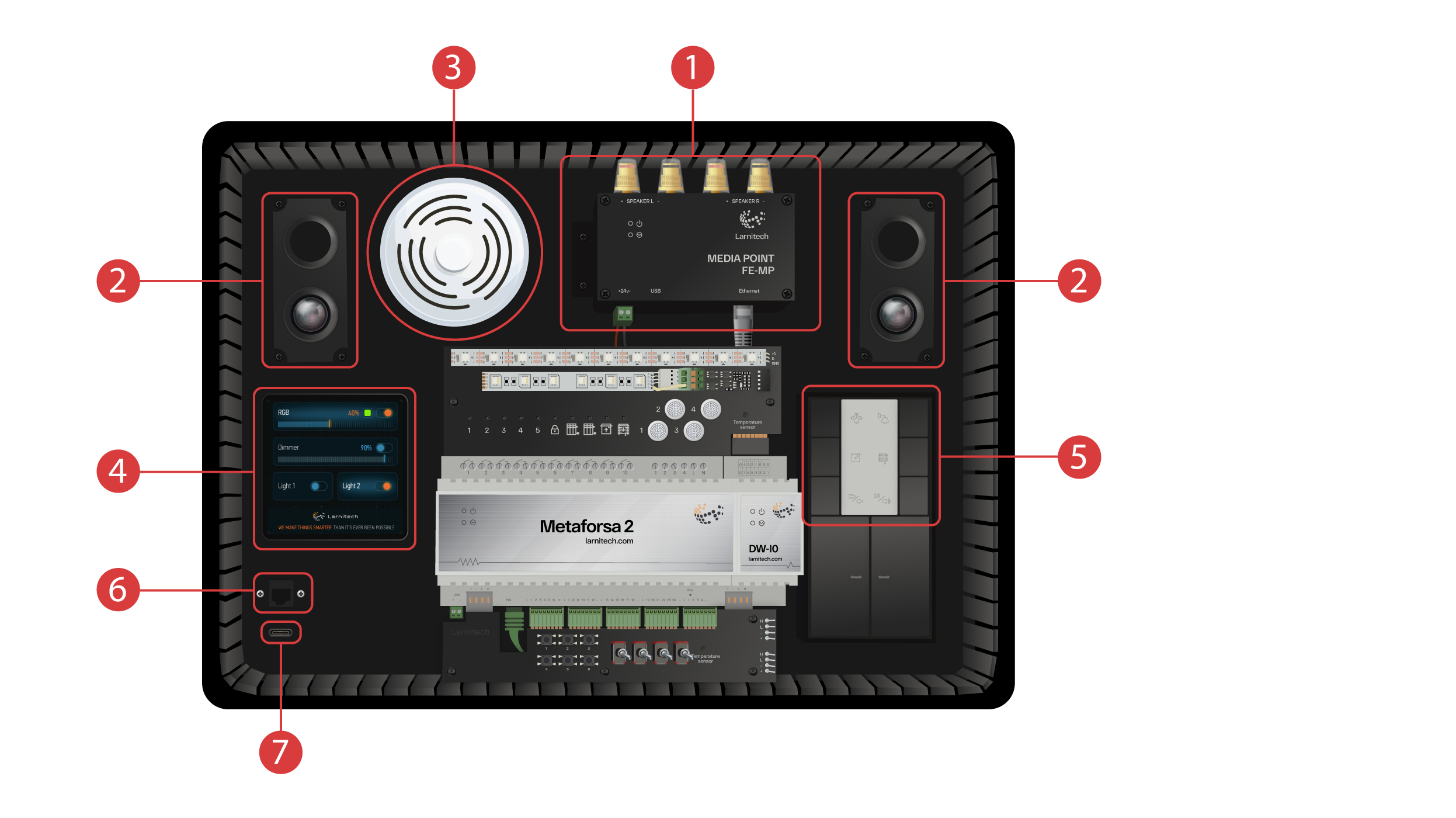
La maleta de demostración también incluye lo siguiente:
① - un Media Point FE-MP con ② dos oradores;
③ - Un sensor CW-CO2 seis en uno, que mide: Nivel de movimiento, Iluminación, Temperatura, Humedad, Nivel de CO2 y que tiene un transmisor infrarrojo;
④ - un panel sensor LCP4 de 4 pulgadas que puede mostrar una interfaz normal o una interfaz adaptada para paneles de pared;
Dentro de la caja hay un módulo de control de botones BW-SW24 que tiene un teclado JUNG de seis botones y 24 voltios ⑤ conectado a él;
Y un router Wi-Fi, que puede conectarse a Internet a través de un puerto Ethernet ⑥ en el panel frontal de la carcasa o a través de una red Wi-Fi disponible;
Para la fuente de alimentación, hay un puerto Tipo C ⑦, que se encuentra en el panel frontal.
Todo el equipo instalado en el maletín de demostración está alimentado por 20 voltios, lo que es absolutamente seguro para el usuario.
Conecte el cable de alimentación y el cable Ethernet. Si no tiene la posibilidad de conectarse a través de Ethernet, más adelante en este vídeo le demostraremos cómo conectar el router incorporado a su red Wi-Fi.
Para continuar, la aplicación Larnitech debe instalarse en su teléfono inteligente o tableta. Solo tiene que escanear el primer código QR de la parte superior de su maletín.
Si después de instalar e iniciar la aplicación la conexión no se establece automáticamente, deberá conectarse a la red Wi-Fi ‘Larnitech_case_5G’ con la ayuda de su dispositivo móvil. A continuación, inicia la aplicación y escanea el primer código QR en la sección ‘Conexiones’.
Es posible que deba desactivar la transmisión de datos en su dispositivo móvil si el conjunto de demostración no está conectado a Internet.

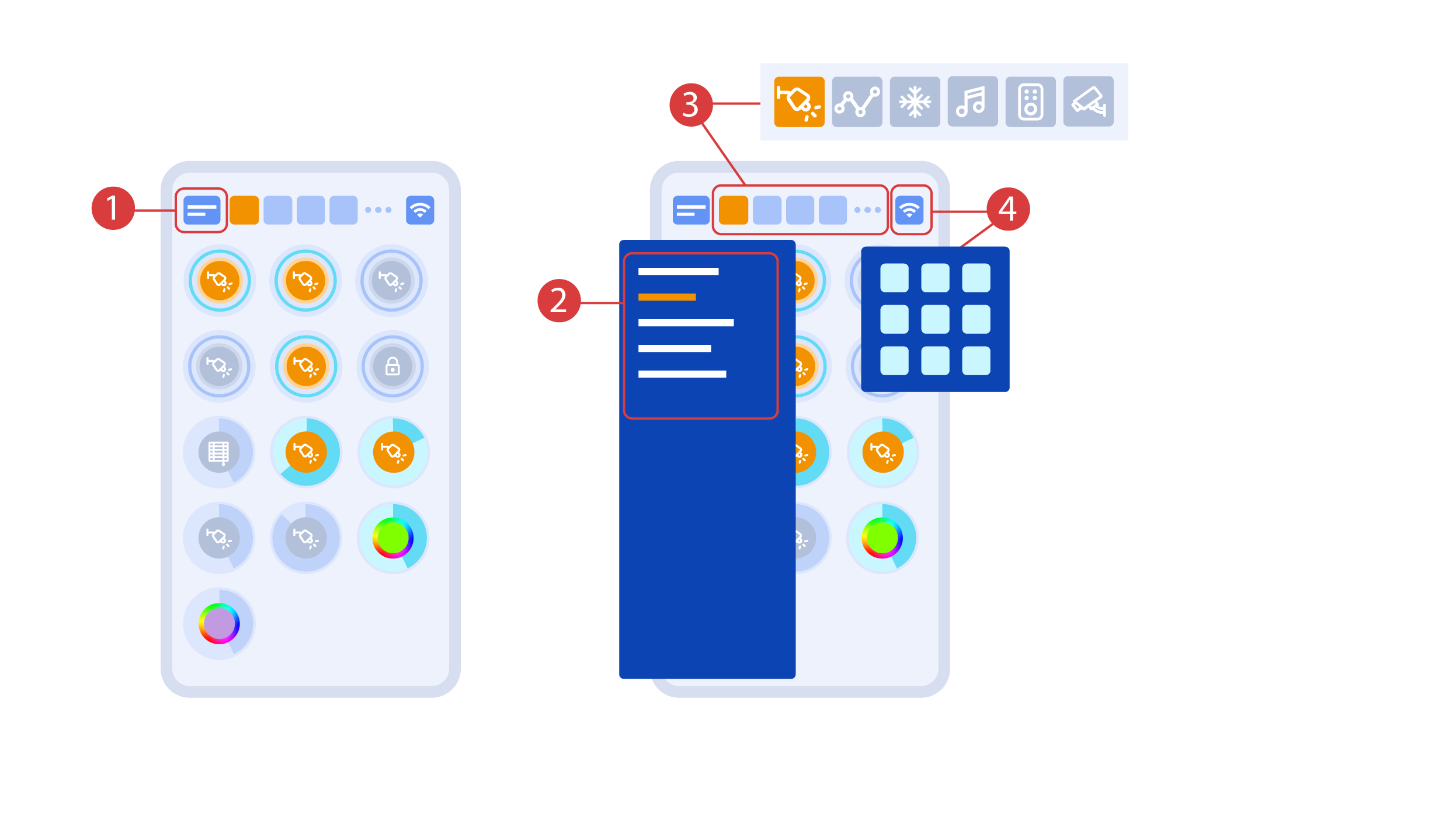
La pantalla principal de la aplicación tiene varios elementos clave. En la esquina superior izquierda se encuentra el menú ‘seleccionar área’ ①.
Solo tiene que hacer clic en una de las áreas disponibles para gestionarla ②.
Luego están los iconos que le permiten elegir los ejecutores, sensores, clima, multimedia, controles remotos y cámaras ③. En la esquina derecha hay un icono para el menú adicional ④. Dentro del icono también puedes ver el estado de la conexión actual.
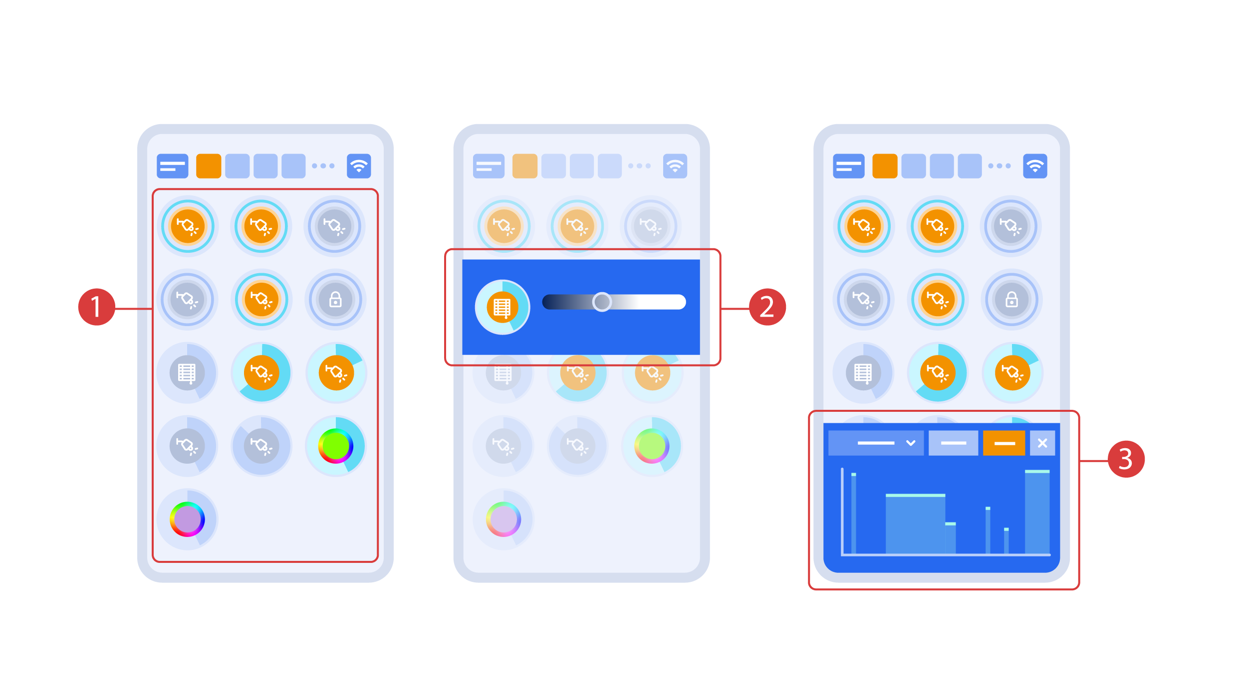
Activar o desactivar los ejecutores ① se hace con un simple clic. Para cambiar el nivel de iluminación ②, el color de las luces o la posición de las persianas, haga doble clic. Para acceder al historial de estado ③ de este ejecutor o sensor, mantenga pulsado el icono durante un segundo.
Una pulsación corta de los botones físicos del panel enciende o apaga la luz. Mantenga pulsado el botón para cambiar el brillo de la luz.
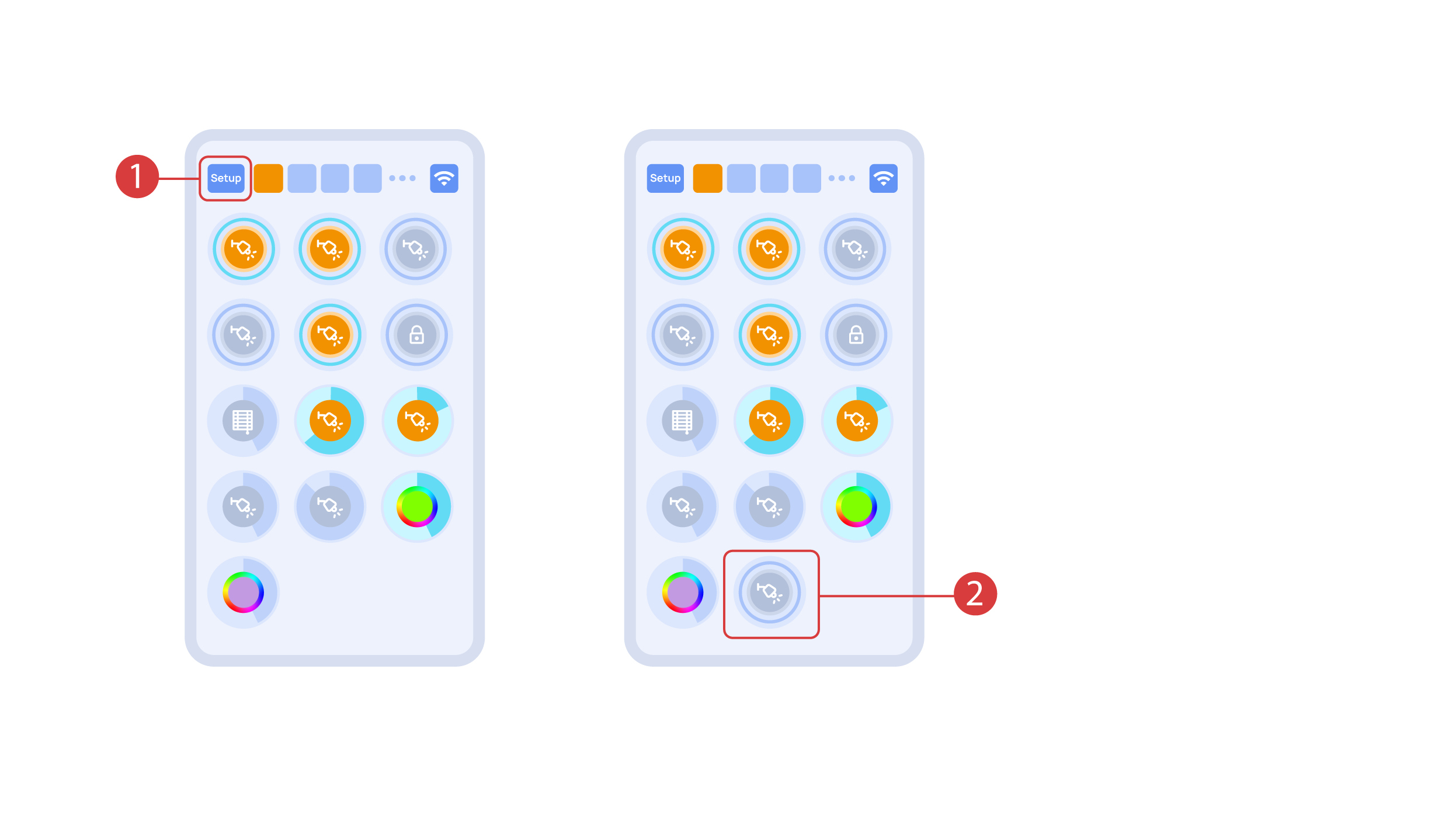
Para demostrar la función Plug and Play, abrimos los ejecutores en el área de Configuración ① y conectamos el módulo al bus CAN. El sistema detecta automáticamente el nuevo módulo y lo añade al área de ‘Configuración’ ②, donde podemos controlar el nuevo módulo al instante.
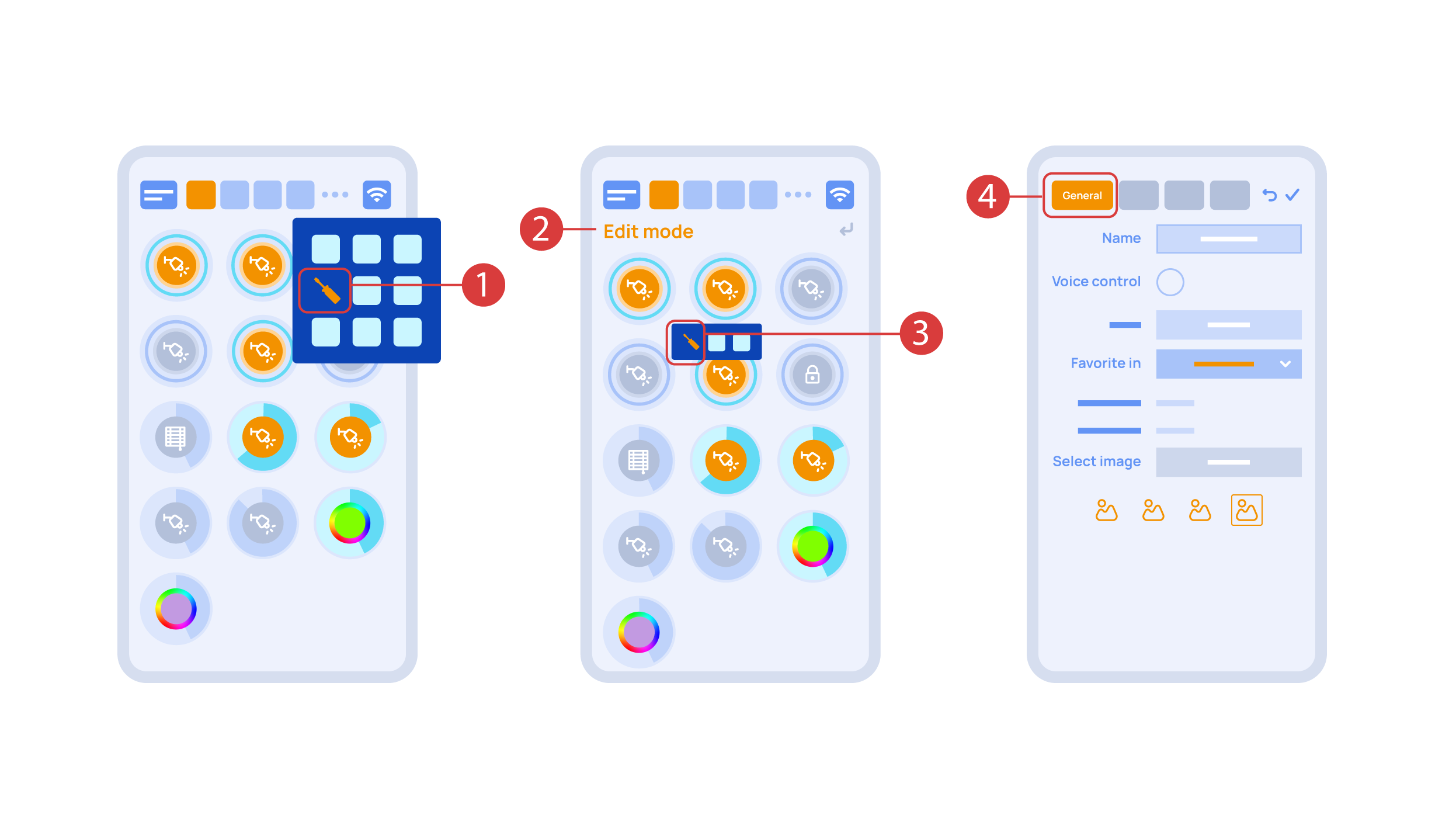
Now we can set up these executors. In order to do this, enter the additional menu ① and activate the edit mode, by pressing the appropriate icon .
Now we are in the edit mode ②, which can be seen from the appropriate notification in the top part of the screen. In this mode, when we press and hold an icon, we can move it among other elements and place it into another Room by placing it in the Area-choosing Menu and then choosing the area that we need. A long press ③ of the element starts the menu, from which we set up the current element.In the ‘General’ ④ section we can change the name of the element, add a voice command for it, change an icon or add the element to ‘Favorites’.
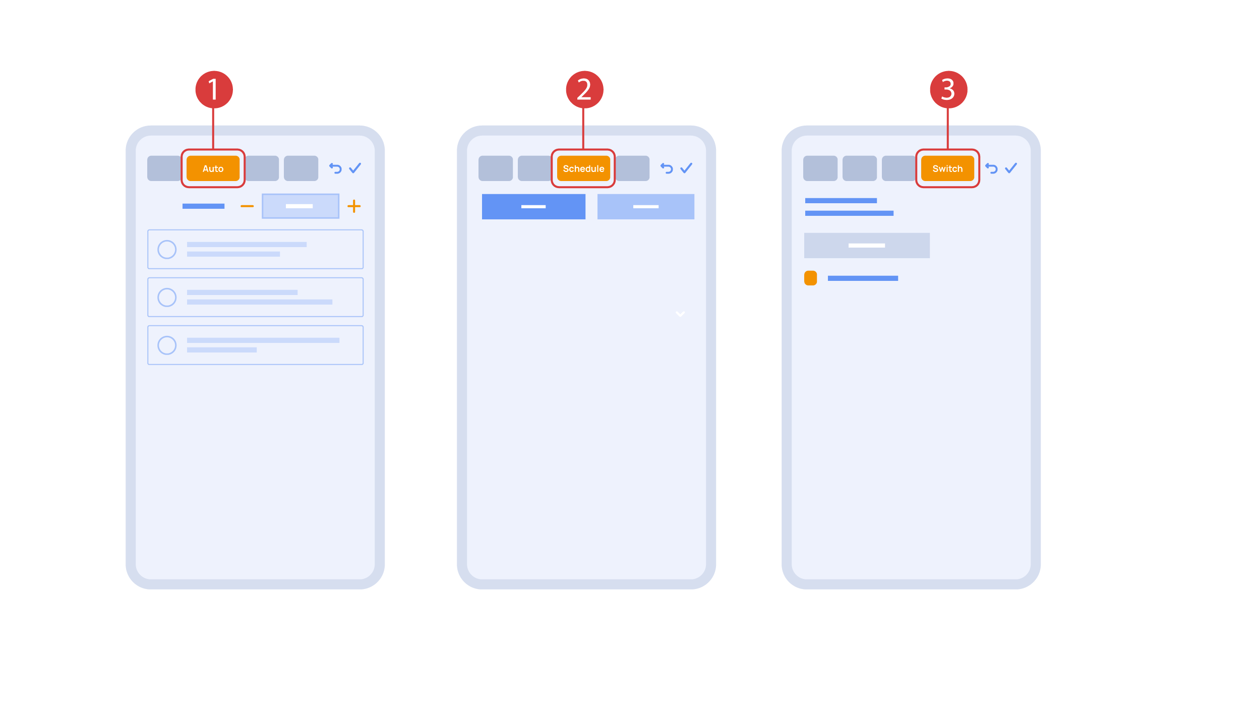
‘Auto’ section ① lets us activate the automation with a few clicks, as well as set up its parameters.
In the ‘schedule’ section ②, you can determine the schedule when the given element will turn on or off, including by using the time of the setting and rising of the sun.
The ‘Switches’ tab ③ lets you bind a button to control the executor.
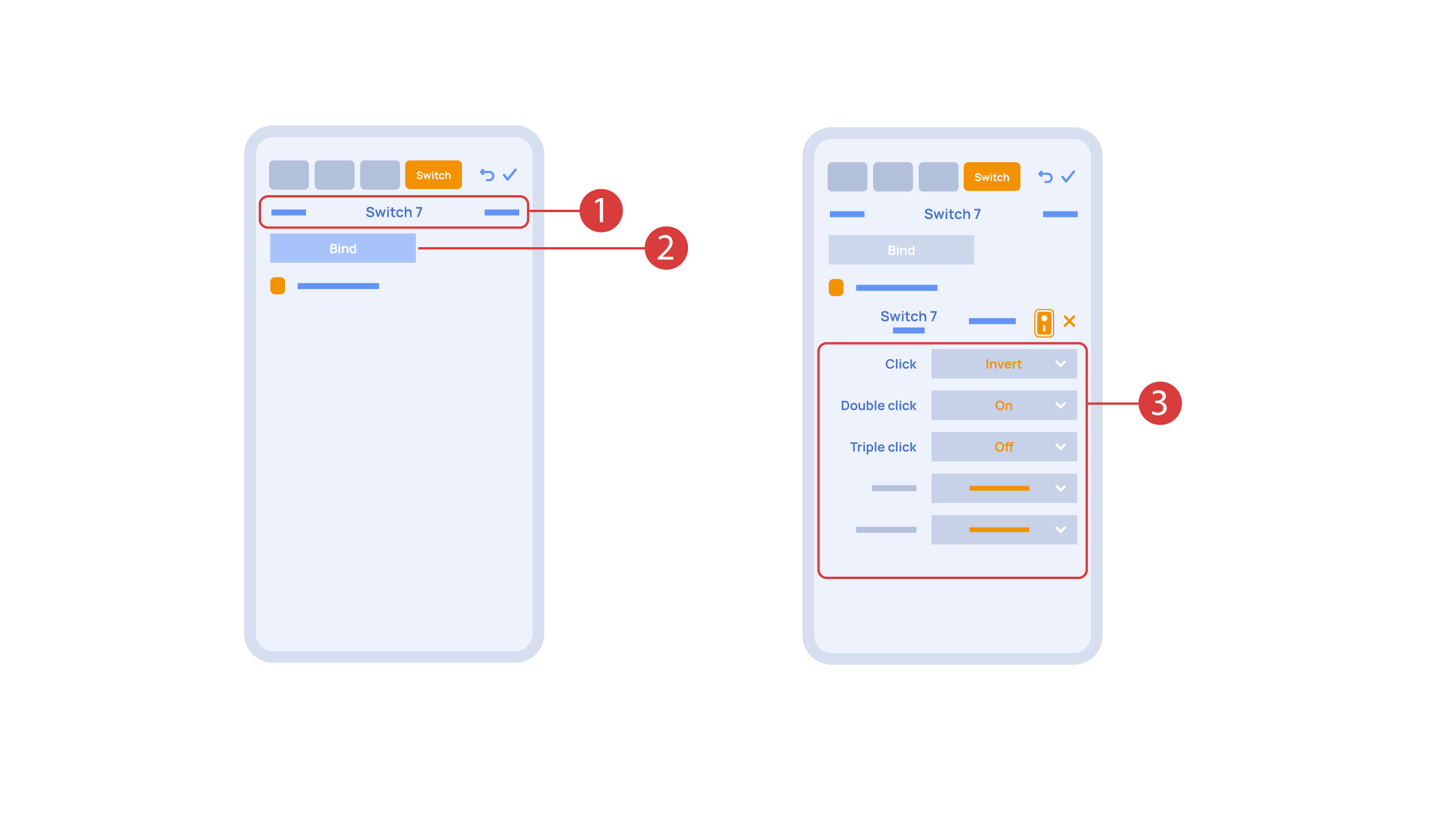
In order to do this, ① we press the button we need to bind. The system displays it, after which we press ‘Bind’② and save the changes. Now this button controls the executor
The ‘Switches’ tab ③ also features additional button setup options. For example, we can program the executor to be controlled with a double or triple click of a button, as well as define an action performed by this, for example ‘only turning on’ or ‘only turning off’ an executor. In this case we are setting up the button to do the following: one click will cause the lamp to toggle, a double click will turn it on and a triple click will turn it off. In this way a single button can perform up to five different actions.
Let’s also set up basic automation of turning an executor on or off with the help of a motion sensor.
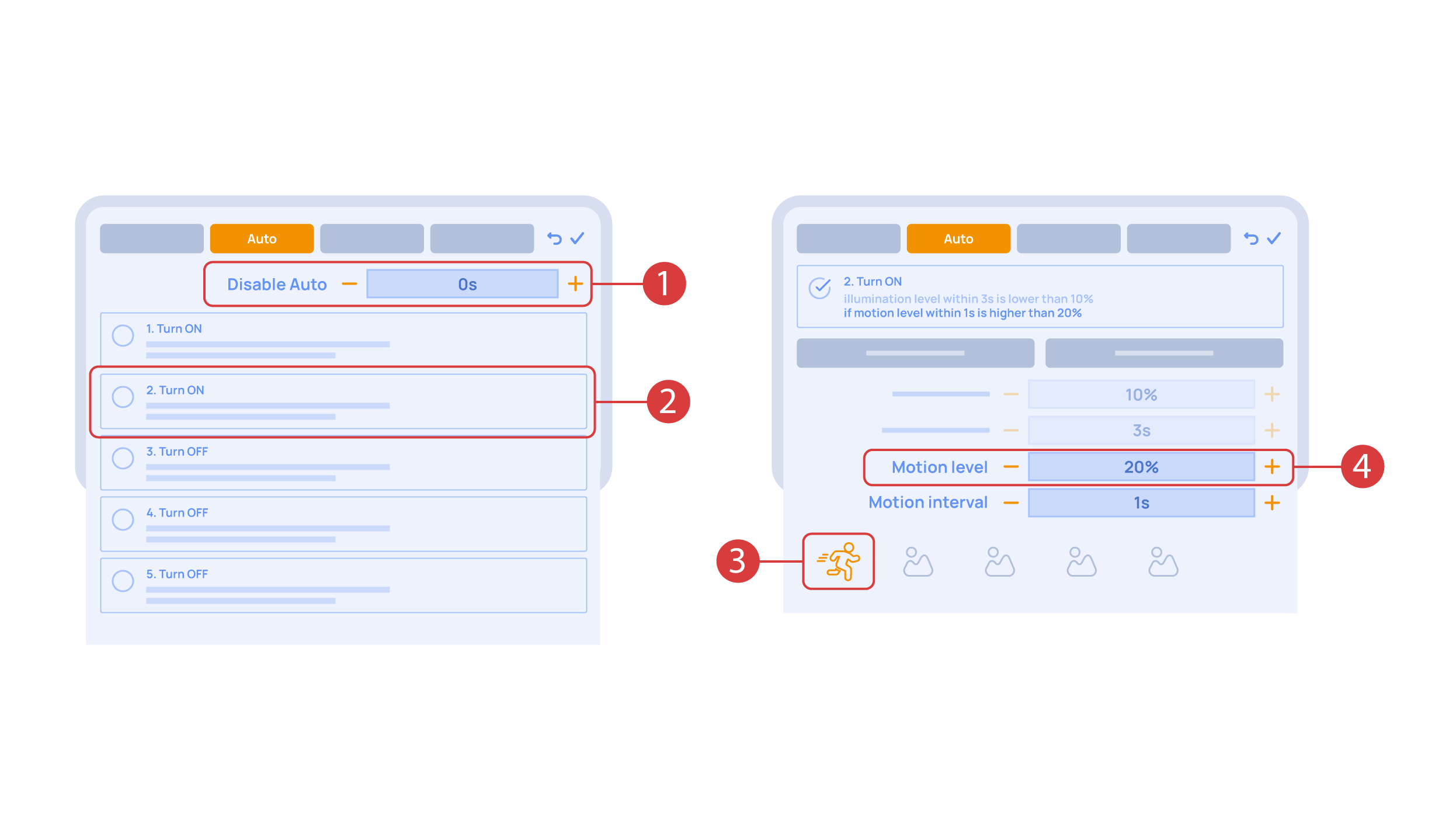
The ‘Auto period’ ① option sets the time for which the automation is disabled after an executor is manually controlled.For our demonstration purposes, we will set it to zero.
Then we will activate the automation ② to turn on the executor when motion is detected. We choose the motion sensor ③ and the level of motion ④. We can also choose a light sensor and its parameters.
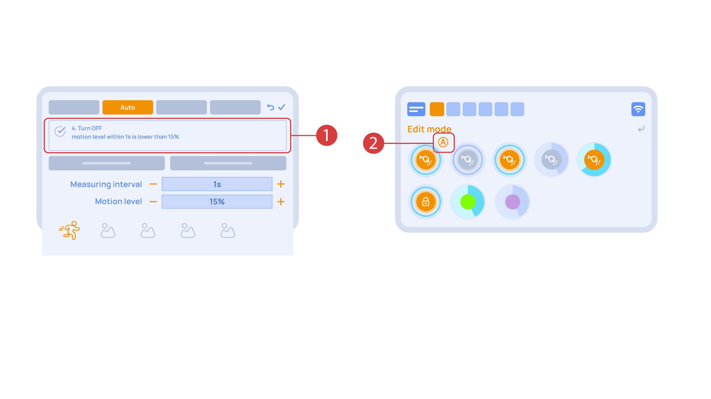
Now we will activate turning off ① of an executor if there is no motion: we choose the same sensor, set a lower threshold and a minimal time.Save the changes.
The extra ‘A’ icon ② will be added to the executor icon, meaning that automation has been set up for it. Now the lamp will be turned on when motion is detected and instantly turned off when no motion is detected.
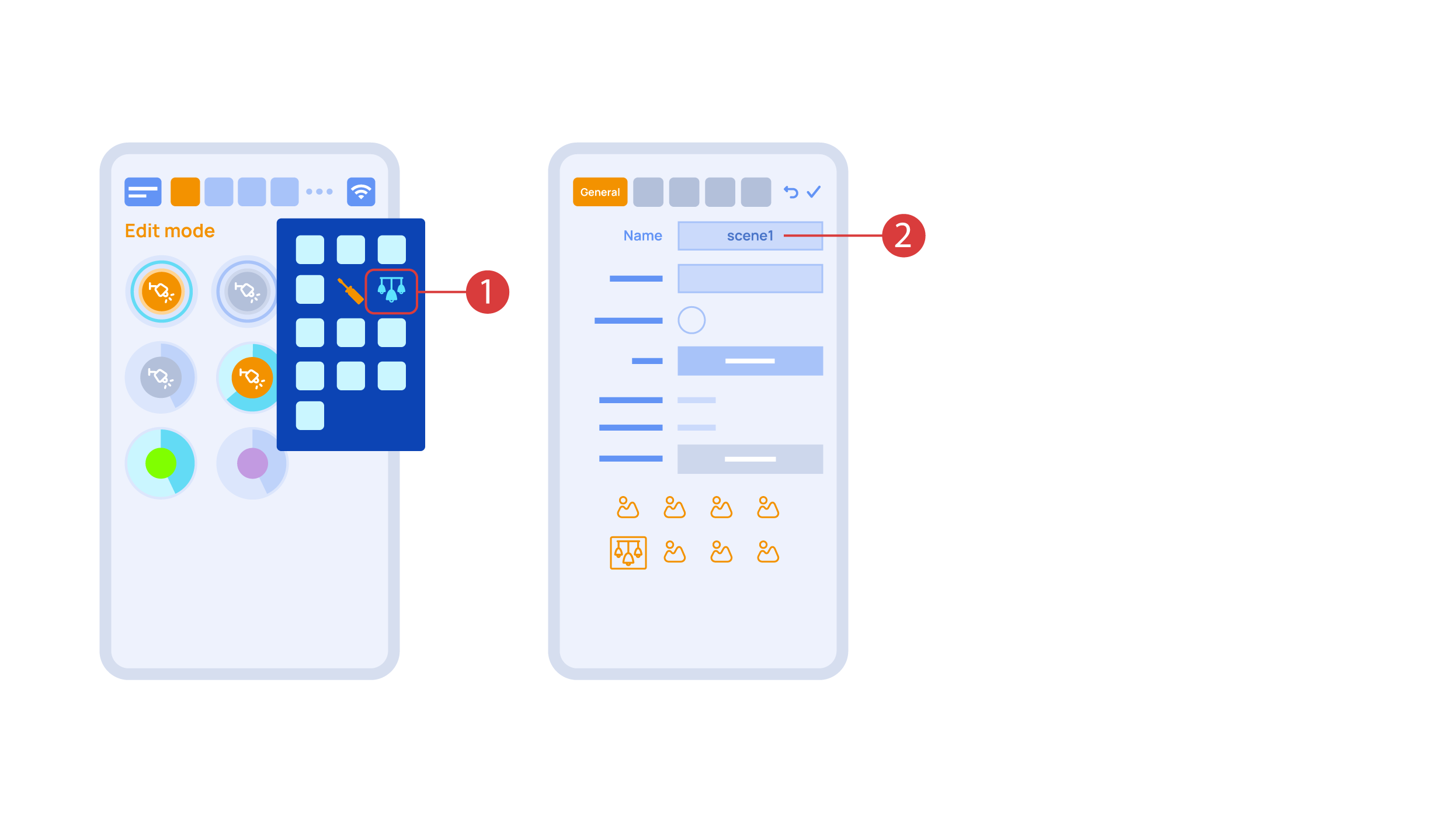
Let’s create a light scheme. For this we need to select the appropriate item in the additional menu ①. Give the light scheme a name ②.
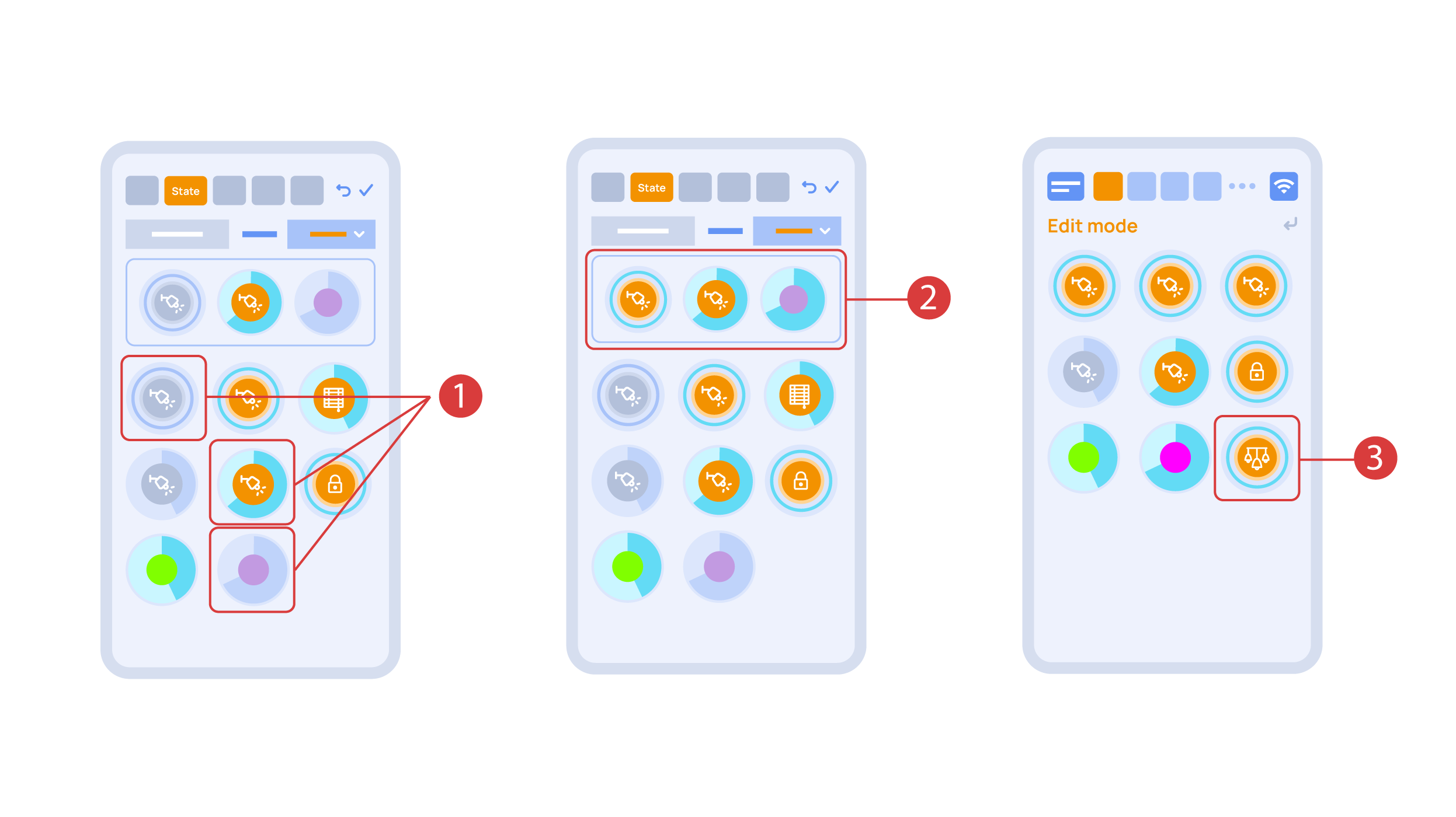
In the ‘State’ tab, use a long press to add the lights we want to use into the light scene ① and set up their state ②. ‘Auto’, ‘Schedule’, ‘Switch’ tabs are the same for all the executors.
Save the changes and we are able to use the newly-created light scheme ③ immediately.
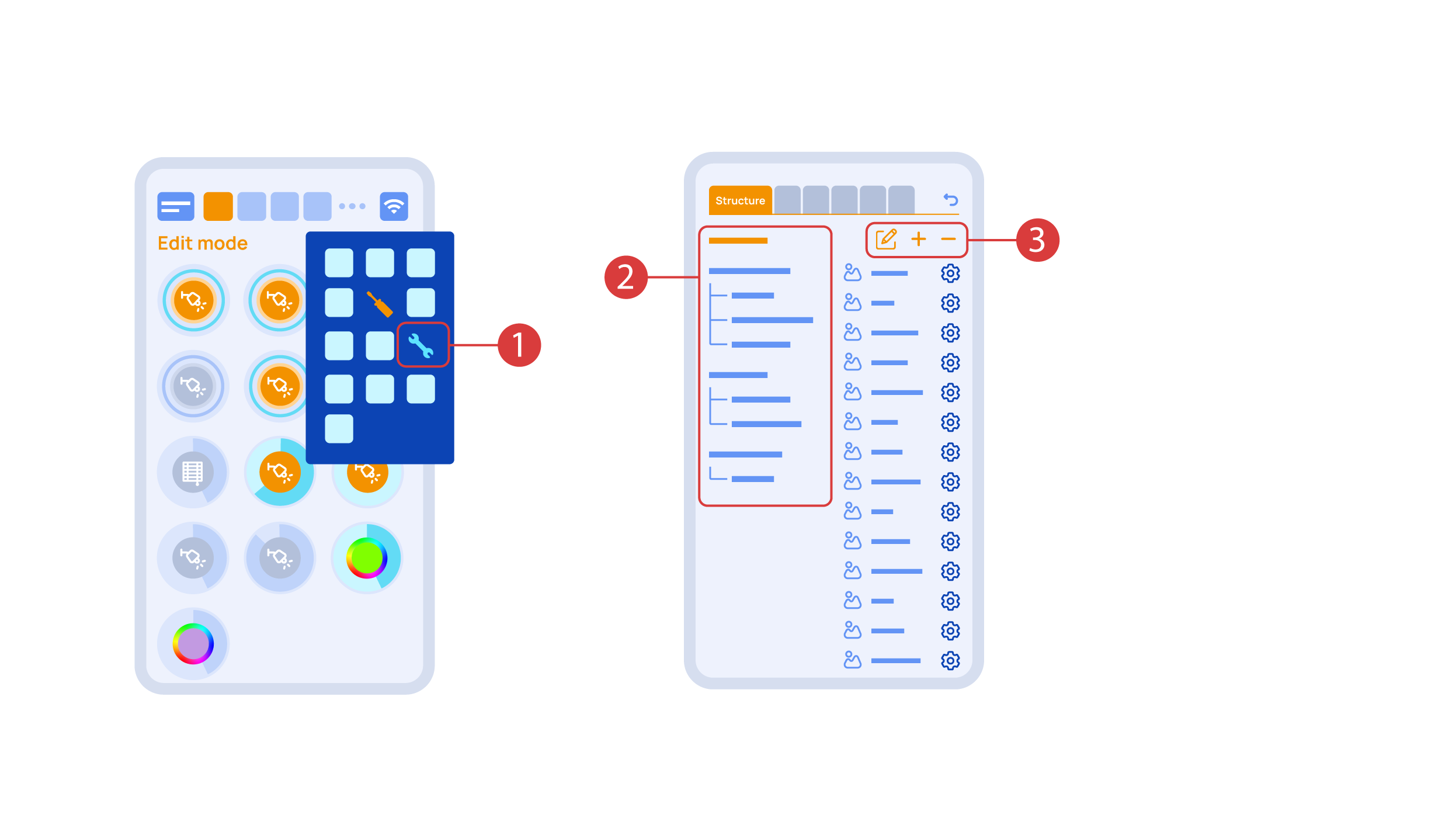
While you are in the Edit Mode, there is a ‘Setup’ ① icon in the additional menu.
Here in the ‘Structure’② tab we can see all the areas.
We can create new ones ④, rename them and move the elements around.
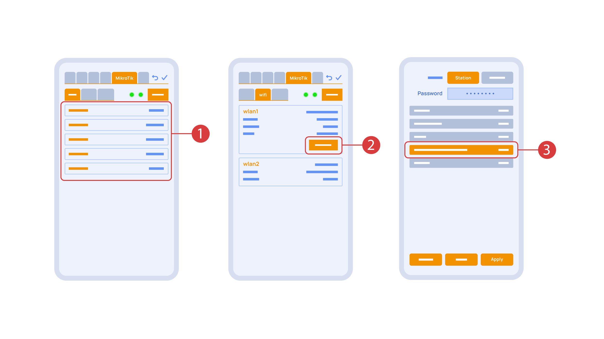
In the ‘Mikrotik’ tab ① you can see the current parameters of your router, which you can also connect to your local Wi-Fi network.
In order to do this, enter the Wi-Fi sub-menu, click the wlan1 interface configuration ②, after which choose the ‘station’ mode, choose a Wi-Fi network out of the list ③ of available ones and enter the connection password.
In the ‘Backups’ tab ① you can see the list of saved configurations, which can be restored if necessary.

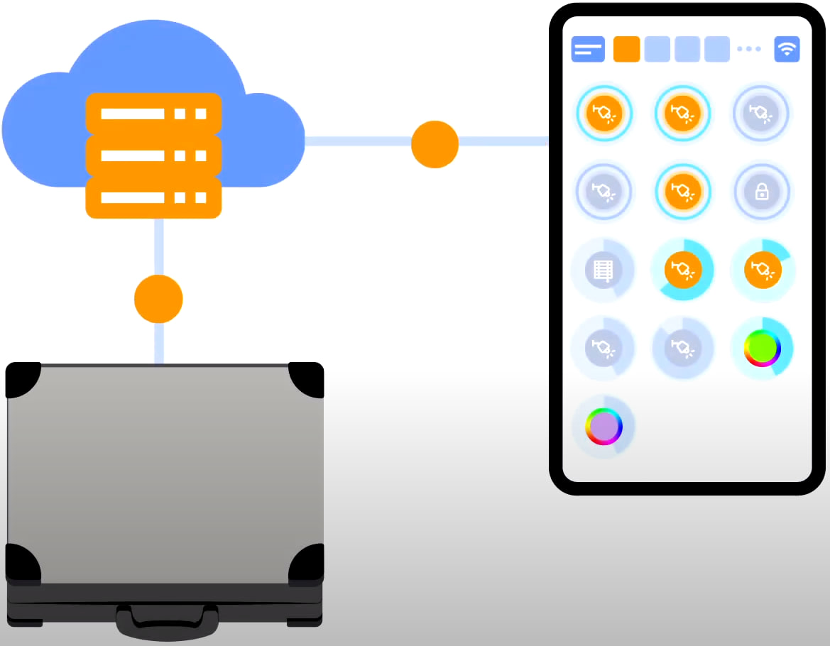
For cloud access to the device, you do not need any extra settings. The app detects the absence of the system in your local network and automatically establishes the connection via the cloud.
We thank you for watching this tutorial! If you have questions or need extra help, please do not hesitate to refer to our technical support team. See you in the next episodes!